EP1759892A2 - Pneu de véhicule et méthode pour sa fabrication - Google Patents
Pneu de véhicule et méthode pour sa fabrication Download PDFInfo
- Publication number
- EP1759892A2 EP1759892A2 EP06116498A EP06116498A EP1759892A2 EP 1759892 A2 EP1759892 A2 EP 1759892A2 EP 06116498 A EP06116498 A EP 06116498A EP 06116498 A EP06116498 A EP 06116498A EP 1759892 A2 EP1759892 A2 EP 1759892A2
- Authority
- EP
- European Patent Office
- Prior art keywords
- core
- profiles
- tire
- profile
- pneumatic vehicle
- Prior art date
- Legal status (The legal status is an assumption and is not a legal conclusion. Google has not performed a legal analysis and makes no representation as to the accuracy of the status listed.)
- Withdrawn
Links
Images

Classifications
-
- B—PERFORMING OPERATIONS; TRANSPORTING
- B60—VEHICLES IN GENERAL
- B60C—VEHICLE TYRES; TYRE INFLATION; TYRE CHANGING; CONNECTING VALVES TO INFLATABLE ELASTIC BODIES IN GENERAL; DEVICES OR ARRANGEMENTS RELATED TO TYRES
- B60C15/00—Tyre beads, e.g. ply turn-up or overlap
- B60C15/06—Flipper strips, fillers, or chafing strips and reinforcing layers for the construction of the bead
- B60C15/0603—Flipper strips, fillers, or chafing strips and reinforcing layers for the construction of the bead characterised by features of the bead filler or apex
- B60C15/0607—Flipper strips, fillers, or chafing strips and reinforcing layers for the construction of the bead characterised by features of the bead filler or apex comprising several parts, e.g. made of different rubbers
-
- B—PERFORMING OPERATIONS; TRANSPORTING
- B60—VEHICLES IN GENERAL
- B60C—VEHICLE TYRES; TYRE INFLATION; TYRE CHANGING; CONNECTING VALVES TO INFLATABLE ELASTIC BODIES IN GENERAL; DEVICES OR ARRANGEMENTS RELATED TO TYRES
- B60C17/00—Tyres characterised by means enabling restricted operation in damaged or deflated condition; Accessories therefor
- B60C17/0009—Tyres characterised by means enabling restricted operation in damaged or deflated condition; Accessories therefor comprising sidewall rubber inserts, e.g. crescent shaped inserts
-
- B—PERFORMING OPERATIONS; TRANSPORTING
- B29—WORKING OF PLASTICS; WORKING OF SUBSTANCES IN A PLASTIC STATE IN GENERAL
- B29D—PRODUCING PARTICULAR ARTICLES FROM PLASTICS OR FROM SUBSTANCES IN A PLASTIC STATE
- B29D30/00—Producing pneumatic or solid tyres or parts thereof
- B29D30/06—Pneumatic tyres or parts thereof (e.g. produced by casting, moulding, compression moulding, injection moulding, centrifugal casting)
- B29D30/48—Bead-rings or bead-cores; Treatment thereof prior to building the tyre
- B29D2030/481—Fillers or apexes
Definitions
- the invention relates to a pneumatic vehicle tire in radial design with a profiled tread, a particular multi-layer belt, an inner layer, a single or multi-layer carcass ply, which is placed in bead areas to bead cores and core profiles with the formation of high blows, and optionally introduced into side walls, in Cross-section crescent-shaped reinforcing profiles, which are each arranged between the inner layer and the carcass ply.
- annular encircling reinforcing profiles installed in the region of the sidewalls of the tire are designed with respect to their cross-sectional shape and with regard to the properties of their elastomeric mixture in such a way that they are able to withstand the tire in the event of sudden pressure loss, ie in the event of a breakdown, for a certain period of time or more to maintain a certain mileage self-sustaining.
- a self-supporting tire of the type mentioned is for example from the DE-A-2 331 530 known.
- This tire has annular circumferential elastomeric reinforcing profiles in the sidewalls which have a maximum thickness of from 3% to 15% of the maximum width of the inflated tire.
- the reinforcing profiles are crescent-shaped, so that their thickness gradually decreases towards the bead area and the tire center plane.
- a self-supporting tire is known in which in each side wall, a reinforcing profile is introduced, which over its cross section of several layers of a more flexible material and of several layers of a Stiffer material. Each reinforcing profile is therefore composed of a plurality of layers oriented substantially in the tire transverse direction.
- the U.S. Patent No. 4,287,924 is concerned with a self-supporting tire, in which two crescent-shaped reinforcing profiles are provided per side wall, which are respectively introduced between the inner layer and the carcass, wherein the reinforcing profile adjoining the carcass ply consists of a flexible, softer elastomeric material than that, which to this and adjacent to the inner layer of the tire.
- Other embodiments of self-supporting tires show that U.S. Patent No.
- the reinforcing profile inserted in the region of each side wall between the airtight inner layer and the carcass ply covers on one side an elastomeric core introduced in the region of the strongest point of the reinforcing profile, the other side of which adjoins the inner layer of the tire.
- the modulus of elasticity of the elastomeric material of the reinforcing profile is lower than that of the incorporated elastomeric core.
- Tires for such applications with reinforcing profiles in the sidewalls require core profiles which extend up to about 75% of the section height of the tire and are made comparatively wide at their proximal ends. These core profiles are difficult to produce in the usual manner used extrusion method, since the extruded profiles in the thin sections tear relatively easily.
- Other manufacturing methods, such as calendering, the mold-injection process or the winding of (rubber) strips, in which the core profile is applied directly to the core, are expensive and expensive.
- the invention is based on the object, in particular for heavier and faster passenger cars to provide suitable self-supporting and thus runnable tires available whose core profiles are easier to manufacture and their handling is unproblematic in tire building.
- At least two core profiles are used in each bead area, which can be handled more easily in the construction of the tire and are also simpler to manufacture.
- a high quality and according to a particularly preferred embodiment of the invention self-supporting tire can be provided.
- the core profile which is also referred to in the jargon as Apex, thus consists of at least two individual components, which are produced as extruded strips and assembled on the building drum.
- the core profiles on each other congruent mating surfaces which wedge-shaped, wavy or straight run in practical developments of the invention, the mating surfaces occupy an angle of 30 ° to 70 ° to the radial, and generally extend over a relatively long range to secure To ensure connection.
- the two core profiles can be made of different rubber compounds, which can be adjusted specific properties of the tire.
- one core profile of a relatively soft, and the other core profile of a relatively hard rubber can be made of different rubber compounds, which can be adjusted specific properties of the tire.
- the one core profile has a smaller volume than the other core profile.
- the construction of the tire with core and two core profiles is possible in a simple and rational way.
- the tire is built on a tire building drum by successively laying the inner layer, the reinforcing profiles and the carcass ply (s). Thereafter, either the core with the prefabricated first core profile is first attached to the drum, after which these profiles are firmly pressed or rolled, wherein then the second core profile overlapping on the first core profile and the carcass are positioned and pressed.
- the rolling of the core profiles in the area of the drum shoulders is facilitated if the core profiles are preformed according to or approximately to the rounding of the drum shoulders.
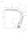
- Fig. 1 shows an inventively designed, self-supporting tire in cross section.
- Self-supporting tires are at a pressure loss in the event of a breakdown in a position to remain at least for a certain mileage so viable that a further journey is possible.
- the drawing figure shows the essential components of the tire, namely a profiled tread 1, here a two-layered belt 2, a particular single-layer, in tires with high load capacity preferably two-ply, running carcass ply 3, an airtight or substantially airtight running inner layer 4, bead areas each with a bead core 5, which consists of a plurality of core wires 6, with core profiles 7, 8 and side walls 9.
- Each side wall 9 is reinforced with a cross-sectionally approximately crescent-shaped reinforcing profile 10.
- the layers of the belt 2 may consist in a known manner of embedded in a rubber compound reinforcements, preferably steel cord, the steel cords in each layer parallel to each other, but are arranged crossed with respect to the steel cords in the or the adjacent layers.
- the steel cords with the tire circumferential direction each enclose an angle of 15 ° to 30 °.
- the reinforcing profiles 10 are arranged between the inner layer 4 and the carcass ply 3 and, together with the core profiles 7, 8, provide the tire with self-bearing capability in the event of pressure loss, so that onward travel is possible over a certain period of time and at reduced speed.
- the reinforcing profiles 10 consist of a very stiff, tear resistant rubber compound with a Shore A hardness of about 75 and range starting at a height h 1 of 15% to 25% of the section height H of the tire, which is measured from the rim transition E, to below the end portions of the belt 2. Their largest thickness, which may be 10 mm or more, has the reinforcing profiles 10 between 50% and 80% of the section height H, which simultaneously represents the radials of the vehicle tire.
- the reinforcing profiles 10 may also be designed in several parts and therefore consist of different rubber compounds. If the core profiles 7.8 are used in a standard tire without runflat ability, the reinforcing profiles would be omitted.
- the carcass ply 3 runs around the bead core 5 and its core profiles 7, 8 from the inside to the outside and is returned to itself, the portion of the carcass ply 3 extending back in the direction of the belt 2, the carcass ply 3a extends slightly beyond the core profiles 7, 8.
- the core profile 7 seated on the bead core 5 preferably extends to a height h 3 which amounts to 30% to 60% of the section height H of the tire.
- the core profile 8 positioned on the bead core 6 extends to a height h 4 which is slightly larger than h 3 and up to 70% of the cross-sectional height H.
- the two core profiles 7, 8 consist of a very stiff, tear-resistant rubber compound with a Shore A hardness of about 75.
- Each core profile 7, 8 can also be designed in several parts and thus consist of different rubber compounds. It is also conceivable to arrange a strength-enhancing fabric layer between the core profiles 7, 8.
- the reinforcing profile 10 and the two core profiles 7, 8 together form a cross-section over a certain extent approximately constant thickness installation.
- the portion of the constant thickness installation extends from the bead core 5 to a height of 50% to 80% of the section height H.
- Fig. 2 shows a preferred way of producing a tire according to the invention on a cylindrical tire building drum 11. Only a section of the tire building drum 11 is shown, where mm indicates the equatorial plane of the drum 11 and aa the axis of rotation of the drum 11.
- the building drum 11 is provided with circumferential recesses on its outer side, which are adapted to the contour of the reinforcing profiles 10. In Fig. 2, only one of the wells is shown.
- the tire building drum 11 can also be divided in a manner known per se over its outer circumference into a plurality of segments which can be moved in and out in the radial direction.
- the shoulder radius of the building drum 11 is relatively small, so that the reinforcing profile 10 is in the finished tire as close as possible to the cores 5. 6.
- the inner layer 4 is placed and positioned in the recesses 12.
- the inner layer can be a wide mixing web or can be applied from a rubber mixture strip by spirally winding it.
- the reinforcing profiles 10 are now positioned in the recesses 12.
- the outer sides of the reinforcing profiles 10 and the inner layer 4 form an at least substantially cylindrical support surface, on which subsequently one or two carcass inserts of different width are placed and spliced.
- the bead core 5, together with the lower core profile 8 has already been positioned and pressed or rolled on corresponding core setting devices as prefabricated core packages.
- the core profile 7 is placed on the core profile 8 following the rounding and rolled. This situation is shown in FIG.
- the two bead cores 5, 6 together with their core profiles 7, 8 can also be set and rolled together.
- the tire is assembled in a conventional manner, wherein initially the carcass ply 3 to the two bead cores 5, 6 and the core profiles 7, 8 is handled and then the other tire components are added.
- FIGS. 3 to 5 show sections through finished bead core packages consisting of the core 5 and core profiles 7, 8.
- the core profiles 7, 8 are bent preformed in order to be largely already adapted to the drum shoulder contour.
- the core profiles 7,8 each have a straight mating surface 12, 13 which extend at an angle to the radial H, which is about 110 °.
- the core profile 7 has an oblique incision 16 in which the core profile 8 is inserted.
Landscapes
- Engineering & Computer Science (AREA)
- Mechanical Engineering (AREA)
- Tires In General (AREA)
- Tyre Moulding (AREA)
Applications Claiming Priority (1)
| Application Number | Priority Date | Filing Date | Title |
|---|---|---|---|
| DE200510041937 DE102005041937A1 (de) | 2005-09-03 | 2005-09-03 | Fahrzeugluftreifen und Verfahren zur Herstellung |
Publications (2)
| Publication Number | Publication Date |
|---|---|
| EP1759892A2 true EP1759892A2 (fr) | 2007-03-07 |
| EP1759892A3 EP1759892A3 (fr) | 2008-07-02 |
Family
ID=37496639
Family Applications (1)
| Application Number | Title | Priority Date | Filing Date |
|---|---|---|---|
| EP20060116498 Withdrawn EP1759892A3 (fr) | 2005-09-03 | 2006-07-03 | Pneu de véhicule et méthode pour sa fabrication |
Country Status (2)
| Country | Link |
|---|---|
| EP (1) | EP1759892A3 (fr) |
| DE (1) | DE102005041937A1 (fr) |
Cited By (4)
| Publication number | Priority date | Publication date | Assignee | Title |
|---|---|---|---|---|
| WO2009004396A1 (fr) * | 2007-06-29 | 2009-01-08 | Pirelli Tyre S.P.A. | Procédé et appareil pour fabriquer des pneus pour des roues de véhicule |
| US20120160390A1 (en) * | 2009-06-22 | 2012-06-28 | Bopha Grisin | Tire Bead for a Large Goods Vehicle |
| US20130174956A1 (en) * | 2010-09-16 | 2013-07-11 | Bridgestone Corporation | Pneumatic tire |
| EP2889161A3 (fr) * | 2013-12-06 | 2015-07-22 | Continental Reifen Deutschland GmbH | Pneumatiques de véhicule |
Family Cites Families (4)
| Publication number | Priority date | Publication date | Assignee | Title |
|---|---|---|---|---|
| IT1245271B (it) * | 1990-09-14 | 1994-09-13 | Pirelli | Carcassa autoportante per pneumatici di autoveicoli |
| DE69211296T2 (de) * | 1991-11-15 | 1997-01-23 | Pirelli | Selbsttragender Luftreifen für Kraftfahrzeugräder mit in die Seitenwände eingearbeiteten elastischen Trageinsätzen |
| JP2002120521A (ja) * | 2000-10-19 | 2002-04-23 | Bridgestone Corp | 空気入りラジアルタイヤ |
| US20050133135A1 (en) * | 2003-12-18 | 2005-06-23 | Corvasce Filomeno G. | Tire with sidewall having at least one internal rubber insert having graduated physical properties comprised of overlapping rubber segments |
-
2005
- 2005-09-03 DE DE200510041937 patent/DE102005041937A1/de not_active Withdrawn
-
2006
- 2006-07-03 EP EP20060116498 patent/EP1759892A3/fr not_active Withdrawn
Cited By (6)
| Publication number | Priority date | Publication date | Assignee | Title |
|---|---|---|---|---|
| WO2009004396A1 (fr) * | 2007-06-29 | 2009-01-08 | Pirelli Tyre S.P.A. | Procédé et appareil pour fabriquer des pneus pour des roues de véhicule |
| US20120160390A1 (en) * | 2009-06-22 | 2012-06-28 | Bopha Grisin | Tire Bead for a Large Goods Vehicle |
| US8839833B2 (en) * | 2009-06-22 | 2014-09-23 | Michelin Recherche Et Techniques S.A. | Tire bead for a large goods vehicle |
| US20130174956A1 (en) * | 2010-09-16 | 2013-07-11 | Bridgestone Corporation | Pneumatic tire |
| US9272584B2 (en) * | 2010-09-16 | 2016-03-01 | Bridgestone Corporation | Pneumatic tire |
| EP2889161A3 (fr) * | 2013-12-06 | 2015-07-22 | Continental Reifen Deutschland GmbH | Pneumatiques de véhicule |
Also Published As
| Publication number | Publication date |
|---|---|
| DE102005041937A1 (de) | 2007-03-08 |
| EP1759892A3 (fr) | 2008-07-02 |
Similar Documents
| Publication | Publication Date | Title |
|---|---|---|
| DE69604768T2 (de) | Luftreifen und Verfahren zur Herstellung | |
| DE60304974T2 (de) | Selbstdichtender Luftreifen | |
| EP2627523B1 (fr) | Pneumatique de véhicule | |
| WO2008025598A1 (fr) | Procédé de fabrication d'un bandage cru ou d'une carcasse de bandage cru sur un tambour de confection de bandages | |
| EP1970221B1 (fr) | Pneus de véhicule dotés de propriétés d'urgence | |
| DE69802966T2 (de) | Radeinheit mit sicherheitsmembran für reifen | |
| DE60209012T2 (de) | Lufreifen mit asymmetrischen und verstärkten seitenwänden | |
| EP0881105B1 (fr) | Bandage pneumatique pour véhicule | |
| WO2009053131A1 (fr) | Pneumatique de véhicule | |
| DE69710931T2 (de) | Verstärkungsgürtel für reifen | |
| DE10138670A1 (de) | Fahrzeugluftreifen mit einer Gürtelbandage | |
| DE102004059771B4 (de) | Fahrzeugluftreifen und Verfahren zur Herstellung | |
| EP1759892A2 (fr) | Pneu de véhicule et méthode pour sa fabrication | |
| EP1667855B1 (fr) | Pneumatique de vehicule | |
| EP1982849B1 (fr) | Pneus de véhicule dotés de propriétés d'urgence | |
| WO2007147686A1 (fr) | Pneumatique de véhicule à paroi latérale dotée d'un profilé de renforcement | |
| WO2009053132A1 (fr) | Pneumatique de véhicule, ayant des caractéristiques de roulage à plat | |
| DE102004060468A1 (de) | Fahrzeugluftreifen | |
| EP2114700B1 (fr) | Bandage pneumatique pour véhicule doté de propriétés de roulage de secours | |
| EP1816012B1 (fr) | Pneumatique pour roulage à plat avec des profilés de renforcement dans le flanc de pneumatique et procédé de fabrication des profilés de renforcement | |
| DE102008037614B4 (de) | Fahrzeugluftreifen | |
| EP1535763B1 (fr) | Méthode pour la fabrication d'un bandage pneumatique pour véhicules | |
| EP1883546A1 (fr) | Pneumatiques de vehicules et son procede de production | |
| EP3416833B1 (fr) | Pneumatique pour véhicule | |
| DE102008004478A1 (de) | Fahrzeugluftreifen mit Notlaufeigenschaften bei Druckluftverlust |
Legal Events
| Date | Code | Title | Description |
|---|---|---|---|
| PUAI | Public reference made under article 153(3) epc to a published international application that has entered the european phase |
Free format text: ORIGINAL CODE: 0009012 |
|
| AK | Designated contracting states |
Kind code of ref document: A2 Designated state(s): AT BE BG CH CY CZ DE DK EE ES FI FR GB GR HU IE IS IT LI LT LU LV MC NL PL PT RO SE SI SK TR |
|
| AX | Request for extension of the european patent |
Extension state: AL BA HR MK YU |
|
| PUAL | Search report despatched |
Free format text: ORIGINAL CODE: 0009013 |
|
| AK | Designated contracting states |
Kind code of ref document: A3 Designated state(s): AT BE BG CH CY CZ DE DK EE ES FI FR GB GR HU IE IS IT LI LT LU LV MC NL PL PT RO SE SI SK TR |
|
| AX | Request for extension of the european patent |
Extension state: AL BA HR MK RS |
|
| STAA | Information on the status of an ep patent application or granted ep patent |
Free format text: STATUS: THE APPLICATION HAS BEEN WITHDRAWN |
|
| 17P | Request for examination filed |
Effective date: 20090105 |
|
| AKX | Designation fees paid |
Designated state(s): AT BE BG CH CY CZ DE DK EE ES FI FR GB GR HU IE IS IT LI LT LU LV MC NL PL PT RO SE SI SK TR |
|
| 17Q | First examination report despatched |
Effective date: 20090211 |
|
| 18W | Application withdrawn |
Effective date: 20090217 |