EP1759910A2 - Stufenlos verstellbares Riemengetriebe (CVT) für ein im Grätschschritt zu benutzendes Fahrzeug - Google Patents
Stufenlos verstellbares Riemengetriebe (CVT) für ein im Grätschschritt zu benutzendes Fahrzeug Download PDFInfo
- Publication number
- EP1759910A2 EP1759910A2 EP06018580A EP06018580A EP1759910A2 EP 1759910 A2 EP1759910 A2 EP 1759910A2 EP 06018580 A EP06018580 A EP 06018580A EP 06018580 A EP06018580 A EP 06018580A EP 1759910 A2 EP1759910 A2 EP 1759910A2
- Authority
- EP
- European Patent Office
- Prior art keywords
- sheave
- electric motor
- primary
- shaft
- primary sheave
- Prior art date
- Legal status (The legal status is an assumption and is not a legal conclusion. Google has not performed a legal analysis and makes no representation as to the accuracy of the status listed.)
- Withdrawn
Links
Images


Classifications
-
- B—PERFORMING OPERATIONS; TRANSPORTING
- B62—LAND VEHICLES FOR TRAVELLING OTHERWISE THAN ON RAILS
- B62K—CYCLES; CYCLE FRAMES; CYCLE STEERING DEVICES; RIDER-OPERATED TERMINAL CONTROLS SPECIALLY ADAPTED FOR CYCLES; CYCLE AXLE SUSPENSIONS; CYCLE SIDECARS, FORECARS, OR THE LIKE
- B62K5/00—Cycles with handlebars, equipped with three or more main road wheels
- B62K5/01—Motorcycles with four or more wheels
-
- F—MECHANICAL ENGINEERING; LIGHTING; HEATING; WEAPONS; BLASTING
- F16—ENGINEERING ELEMENTS AND UNITS; GENERAL MEASURES FOR PRODUCING AND MAINTAINING EFFECTIVE FUNCTIONING OF MACHINES OR INSTALLATIONS; THERMAL INSULATION IN GENERAL
- F16H—GEARING
- F16H63/00—Control outputs from the control unit to change-speed- or reversing-gearings for conveying rotary motion or to other devices than the final output mechanism
- F16H63/02—Final output mechanisms therefor; Actuating means for the final output mechanisms
- F16H63/04—Final output mechanisms therefor; Actuating means for the final output mechanisms a single final output mechanism being moved by a single final actuating mechanism
- F16H63/06—Final output mechanisms therefor; Actuating means for the final output mechanisms a single final output mechanism being moved by a single final actuating mechanism the final output mechanism having an indefinite number of positions
- F16H63/062—Final output mechanisms therefor; Actuating means for the final output mechanisms a single final output mechanism being moved by a single final actuating mechanism the final output mechanism having an indefinite number of positions electric or electro-mechanical actuating means
-
- F—MECHANICAL ENGINEERING; LIGHTING; HEATING; WEAPONS; BLASTING
- F16—ENGINEERING ELEMENTS AND UNITS; GENERAL MEASURES FOR PRODUCING AND MAINTAINING EFFECTIVE FUNCTIONING OF MACHINES OR INSTALLATIONS; THERMAL INSULATION IN GENERAL
- F16H—GEARING
- F16H9/00—Gearings for conveying rotary motion with variable gear ratio, or for reversing rotary motion, by endless flexible members
- F16H9/02—Gearings for conveying rotary motion with variable gear ratio, or for reversing rotary motion, by endless flexible members without members having orbital motion
- F16H9/04—Gearings for conveying rotary motion with variable gear ratio, or for reversing rotary motion, by endless flexible members without members having orbital motion using belts, V-belts, or ropes
- F16H9/12—Gearings for conveying rotary motion with variable gear ratio, or for reversing rotary motion, by endless flexible members without members having orbital motion using belts, V-belts, or ropes engaging a pulley built-up out of relatively axially-adjustable parts in which the belt engages the opposite flanges of the pulley directly without interposed belt-supporting members
- F16H9/16—Gearings for conveying rotary motion with variable gear ratio, or for reversing rotary motion, by endless flexible members without members having orbital motion using belts, V-belts, or ropes engaging a pulley built-up out of relatively axially-adjustable parts in which the belt engages the opposite flanges of the pulley directly without interposed belt-supporting members using two pulleys, both built-up out of adjustable conical parts
- F16H9/18—Gearings for conveying rotary motion with variable gear ratio, or for reversing rotary motion, by endless flexible members without members having orbital motion using belts, V-belts, or ropes engaging a pulley built-up out of relatively axially-adjustable parts in which the belt engages the opposite flanges of the pulley directly without interposed belt-supporting members using two pulleys, both built-up out of adjustable conical parts only one flange of each pulley being adjustable
-
- Y—GENERAL TAGGING OF NEW TECHNOLOGICAL DEVELOPMENTS; GENERAL TAGGING OF CROSS-SECTIONAL TECHNOLOGIES SPANNING OVER SEVERAL SECTIONS OF THE IPC; TECHNICAL SUBJECTS COVERED BY FORMER USPC CROSS-REFERENCE ART COLLECTIONS [XRACs] AND DIGESTS
- Y10—TECHNICAL SUBJECTS COVERED BY FORMER USPC
- Y10T—TECHNICAL SUBJECTS COVERED BY FORMER US CLASSIFICATION
- Y10T74/00—Machine element or mechanism
- Y10T74/19—Gearing
- Y10T74/19219—Interchangeably locked
- Y10T74/19242—Combined gear and clutch
-
- Y—GENERAL TAGGING OF NEW TECHNOLOGICAL DEVELOPMENTS; GENERAL TAGGING OF CROSS-SECTIONAL TECHNOLOGIES SPANNING OVER SEVERAL SECTIONS OF THE IPC; TECHNICAL SUBJECTS COVERED BY FORMER USPC CROSS-REFERENCE ART COLLECTIONS [XRACs] AND DIGESTS
- Y10—TECHNICAL SUBJECTS COVERED BY FORMER USPC
- Y10T—TECHNICAL SUBJECTS COVERED BY FORMER US CLASSIFICATION
- Y10T74/00—Machine element or mechanism
- Y10T74/19—Gearing
- Y10T74/19219—Interchangeably locked
- Y10T74/19377—Slidable keys or clutches
- Y10T74/19414—Single clutch shaft
- Y10T74/19419—Progressive
- Y10T74/19442—Single key
- Y10T74/19451—Spur gears
- Y10T74/1946—Sliding clutch carrier
Definitions
- the present invention relates to a V-belt continuously variable transmission, a straddle-type vehicle having a V-belt continuously variable transmission (CVT) for transmitting driving force of an engine to a driving wheel disposed below a seat, and relates to a power unit composed of an engine and a V-belt CVT attached to a side of a crankcase of the engine.
- VVT V-belt continuously variable transmission
- ATV all-terrain vehicle
- each wheel had a wide and low-pressure balloon tire or the like, on the left and right sides of the front and rear sides of a body frame, the upper part of the body frame is provided with steering handlebars, a fuel tank, and a straddle-type seat, sequentially from the front wheel side to the rear wheel side, and a V-belt CVT for transmitting driving force of an engine to driving wheels is disposed below the seat (see Patent Document 1, for example).
- the above V-belt CVT includes: a primary sheave disposed on a primary sheave shaft, to which driving force of the engine is input, and having a movable sheave half and a fixed sheave half to form a V-groove for receiving a belt; a secondary sheave disposed on a secondary sheave shaft, from which driving force for the driving wheels is output, and having a movable sheave half and a fixed sheave half to form a V-groove for receiving a belt; an endless V-belt received in the respective V-grooves of the primary sheave and the secondary sheave to transmit rotational driving force between both the sheaves; and a sheave drive mechanism for displacing the movable sheave half of the primary sheave in the axial direction to control the speed change ratio through resulting variations in respective groove widths of the primary sheave and the secondary sheave.
- a former type of sheave drive mechanism in general was the so-called centrifugal type which utilized centrifugal force produced according to the engine speed to displace a movable sheave half in the axial direction.
- the sheave drive mechanism of the centrifugal type does not perform groove width control operation (namely, speed change operation) responsively according to changes in the road condition, irrespective of the intention of the rider, until the engine speed has actually fallen because of the increased load from the road. That is, the sheave drive mechanism has a problem of delayed response.
- V-belt CVT for use in scooter-type motorcycles
- a control device for controlling the electric motor
- a sheave drive mechanism for transmitting driving force of the electric motor to the movable sheave of the primary sheave to control the respective groove widths of the primary sheave and the secondary sheave
- a scooter-type motorcycle is provided with an integral power unit composed of an engine and a V-belt CVT attached to a side of a crankcase of the engine.
- the power unit may be swingably suspended from a body frame to function as a swing arm for swingably supporting a rear wheel.
- Patent Document 1 JP-A-2004-156657
- Patent Document 2 JP-B-3043061
- V-belt CVTs for use in ATVs, to electrically control the respective groove widths of the primary sheave and the secondary sheave in order to improve response in the speed change process.
- the belt chamber is large in the vehicle width direction because of a footrest for the rider provided on the outer side of the crankcase and the V-belt CVT, and the electric motor, when thoughtlessly provided on the outer side of the vehicle body, would prevent the rider from putting his/her foot in place, thereby spoiling the usability.
- the service life of the electric motor and/or the measurement accuracy of the electric motor may be reduced, whereby the original performance cannot be achieved.
- the present invention is made in view of solving the foregoing problems, and therefore has an object to provide a V-belt CVT, a straddle-type vehicle, and power unit achieving speed change operation highly responsive to the vehicle running condition with compact yet durable structure.
- a V-belt continuously variable transmission for a straddle-type vehicle for transmitting driving force of an engine to a driving wheel
- the V-belt continuously variable transmission comprising a primary sheave, and a secondary sheave
- a movable sheave half of the primary sheave is located on an outer side in a vehicle width direction with respect to a fixed sheave half of the primary sheave
- a sheave drive mechanism located on an outer side in the vehicle width direction with respect to the movable sheave half of the primary sheave, to control respective groove widths of the primary sheave and the secondary sheave through driving force of an electric motor, wherein at least a part of the electric motor is located above and in front of a primary sheave shaft as viewed in a sheave shaft direction.
- a footrest of the straddle-type vehicle is located on an outer side of the V-belt continuously variable transmission in the vehicle width direction, and below the primary sheave shaft and a secondary sheave shaft.
- the primary sheave and the electric motor overlap with each other as viewed in the sheave shaft direction.
- a rotary shaft of the electric motor may be coincident in direction with the primary sheave shaft.
- the electric motor may be located closer to the primary sheave shaft than a speed reduction mechanism of the sheave drive mechanism is, as viewed in the sheave shaft direction.
- sheave drive mechanism may be located around the primary sheave shaft and the electric motor is located on an outer side of the sheave drive mechanism.
- an outer periphery of the secondary sheave may be located adjacent to an outer periphery of the primary sheave.
- a straddle-type vehicle in particular all terrain vehicle, comprising a V-belt continuously variable transmission according to one of the above embodiments.
- an exhaust pipe of the engine is disposed above the V-belt continuously variable transmission and the electric motor is located in front of the V-belt continuously variable transmission.
- a front fender is disposed in front of the V-belt continuously variable transmission.
- a power unit comprising an engine, and a V-belt continuously variable transmission, in particular according to one of the above embodiments, disposed on a side of a crankcase of the engine for transmitting driving force of the engine to a driving wheel, the engine having a cylinder block attached to the crankcase, and the V-belt continuously variable transmission comprising a primary sheave, a secondary sheave, a V-belt received in the respective V-grooves of the primary sheave and the secondary sheave, and a sheave drive mechanism for transmitting driving force of the electric motor to a movable sheave half of the primary sheave to control respective groove widths of the primary sheave and the secondary sheave through driving force of an electric motor, wherein the movable sheave half of the primary sheave and the sheave drive mechanism are located on an opposite side from the crankcase with respect to the fixed sheave half of the primary sheave, and the electric motor is located on a
- the primary sheave and the electric motor overlap with each other as viewed in the sheave shaft direction.
- a rotary shaft of the electric motor is coincident in direction with the primary sheave shaft.
- the electric motor is located closer to the primary sheave shaft than a speed reduction mechanism of the sheave drive mechanism is, as viewed in the sheave shaft direction.
- sheave drive mechanism is located around the primary sheave shaft and the electric motor is located on an outer side of the sheave drive mechanism.
- FIGs. 1 through 5 illustrate a straddle-type vehicle and a power unit according to a first embodiment.
- FIGs. 1 is a right side view of the straddle-type vehicle incorporating the power unit according to the first embodiment.
- FIG. 2 is a plan view of the straddle-type vehicle shown in FIG. 1.
- FIG. 3 is a right side view of the power unit mounted in the straddle-type vehicle shown in FIG. 1 with a cover of a V-belt continuously variable transmission (CVT) removed.
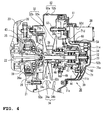
- FIG. 4 is a sectional view taken along the line A-A of FIG. 3.
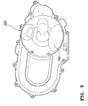
- FIG. 5 is a right side view of the cover of the V-belt CVT shown in FIG. 1.
- “left” and “right” refer to the left and right from the rider's point of view.
- An ATV (all-terrain vehicle) 1 shown in FIGs. 1 and 2 is a straddle-type vehicle having a seat 3, on which the operator (rider) straddles, located generally in the center of the upper part of a body frame 2, and a power unit 4 is located below the seat 3.
- the power unit 4 is an integral unit composed of an engine 20 and a V-belt CVT 30 for transmitting driving force of the engine 20 to driving wheels, attached to a side of a crankcase 21 of the engine 20 (see FIGs. 3 and 4).
- the structure of the ATV 1, and the structures of the engine 20 and the V-belt CVT 30 composing the power unit 4 will be described sequentially below.
- the upper part of the body frame 2 in front of the seat 3 is provided with a fuel tank 6 and steering handlebars 5, sequentially from the seat 3 side.
- Left and right front wheels 8, 8, each having a wide and low-pressure balloon tire 8a are disposed in the front part of the body frame 2 via a front wheel suspension device 7, and left and right rear wheels 10, 10, each having a wide and low-pressure balloon tire 10a, are disposed in the rear part of the frame 2 via a rear wheel suspension device (not shown).
- the body frame 2 is also provided with left and right front fenders 11 for covering the upper side of the respective front wheels 8, left and right rear fenders 12 for covering the upper side of the respective rear wheels 10, and carriers 13, 14 provided on the upper side of the fenders 11, 12 to connect the left and right fenders.
- the body frame 2 is provided with a footboard 15 as a footrest for supporting the foot of the rider on the lower left and right sides of the seat 3.
- a bumper 16 is provided at the front end of the frame 2.
- the body frame 2 is a double-cradle type in which a pair of left and right side frames 17, 17, made of steel tubing and formed generally in a rectangle which is longer sideways, are jointed by a number of cross pipes 18 extending in the vehicle width direction.
- the power unit 4 includes a water-cooled 4-cycle single-cylinder engine 20, and a V-belt CVT 30 bolted to the right side of the engine 20, in the crankshaft direction.
- the engine 20 is mounted on the body frame 2 with an axis of its cylinder inclined upward and forward and a crankshaft 22 (see FIG. 4) oriented horizontally in the vehicle width direction.
- the upper mating surface of a cylinder block 23 is connected to a cylinder head 24, and the lower mating surface of the cylinder block 23 is connected to a crankcase 21 accommodating the crankshaft 22.
- a generator (not shown) is mounted on the left end of the crankshaft 22, while a centrifugal clutch mechanism 25 is mounted on the right end thereof.
- the centrifugal clutch mechanism 25 includes an inner drum 26 spline-coupled with the crankshaft 22 to rotate together therewith, an outer drum 27 disposed to surround an outer periphery of the inner drum 26, and a one-way clutch 28 interposed between bosses of the pair of drums 26, 27.
- the one-way clutch 28 functions to transmit power from the rear wheels to the crankshaft 22 in reverse in order to provide engine braking.
- the V-belt CVT 30 includes: a primary sheave 32 disposed on a primary sheave shaft 31, to which driving force of the engine 20 is input from the crankshaft 22 via the centrifugal clutch mechanism 25, and having a movable sheave half 32a and a fixed sheave half 32b to form a V-groove 32c for receiving a belt; a secondary sheave 34 disposed on a secondary sheave shaft 33 (see FIG.
- the primary sheave shaft 31 is coaxial with the crankshaft 22, and rotatably supported by the centrifugal clutch mechanism 25 and a support member 71 such that the primary sheave shaft 31 is on the right end of the crankshaft 22.
- the left end of the primary sheave shaft 31 facing the crankshaft 22 is formed integrally with a skirt 31 a passing through an opening in the center of an end of a clutch cover 29 and surrounding the right end of the crankshaft 22.
- the skirt 31 a is riveted or otherwise secured to the outer drum 27 of the centrifugal clutch mechanism 25.
- the right end of the primary sheave shaft 31 is rotatably supported, via a bearing 72, on the center of the support member 71 secured to the crankcase 21.
- the die-cast aluminum support member 71 includes a bearing holding part 71 a for supporting the right end of the primary sheave shaft 31 via the bearing 72; four legs 71 b extending in four directions from the bearing holding part 71 a; an annular coupling part 71 c for coupling the legs 71 b with a specific radius; a motor attachment part 71 d formed on the annular coupling part 71 c; and a sensor attachment part 71e. Ends of the legs 71 b are bolted to the crankcase 21.
- the primary sheave shaft 31 supported as described above becomes connected through the centrifugal clutch mechanism 25 to the crankshaft 22 in order to rotate together therewith, when the rotational speed of the crankshaft 22 reaches a specific speed or higher.
- the base end of the clutch cover 29 is secured to the crankcase 21.
- a part of the clutch cover 29 around the opening at the center of its end is provided with a bearing 41 for rotatably supporting the primary sheave shaft 31, and a seal member 42 for sealing between the opening and the outer periphery of the skirt 31 a.
- the clutch cover 29 surrounds a space 43 accommodating the centrifugal clutch mechanism 25 in a liquid-tight manner to prevent oil used for the centrifugal clutch mechanism 25 from leaking into a belt chamber 44 of the V-belt CVT 30.
- a measurement plate 73 as a part to be detected for measurement of rotational speed is secured to the right end of the primary sheave shaft 31 by a nut.
- the measurement plate 73 is composed of a disk 73a and projections for measurement 73b formed on the outer periphery of the disk 73a at regular intervals.
- a rotational speed sensor 74 for measuring rotation of the primary sheave shaft 31 based on the passing of the projections for measurement 73b is attached around the outer periphery of the measurement plate 73 via a sensor attachment part 71 e of the support member 71.
- the movable sheave half 32a of the primary sheave 32 is located on the outer side in the vehicle width direction with respect to the fixed sheave half 32b of the primary sheave 32.
- the outer periphery of the secondary sheave 34 is located adjacent to the outer periphery of the primary sheave 32. This can effectively downsize the V-belt CVT 30 in the longitudinal direction of the vehicle for compactness.
- the sheave drive mechanism 39 includes: a guide tube 46 spline-fitted or otherwise mounted on the outer periphery of the primary sheave shaft 31 so as not to rotate relative thereto; a slider 48 mounted on the outer periphery of the guide tube 46 so as to be movable only axially and to which the movable sheave half 32a is secured; a rotary slide member 47 rotatably coupled to the outer periphery of the slider 48 via a bearing so as not to move axially relative thereto and to which a reciprocating gear 49 is secured; a feed guide part 50 having a ball screw part screwed on the rotary slide member 47 to move the rotary slide member 47 in the direction of the primary sheave shaft 31 according to the rotation direction and amount of the reciprocating gear 49; and a speed reduction gear mechanism 51 for reducing the rotational speed of the electric motor 38 and inputting the reduced rotation to the reciprocating gear 49.
- the feed guide part 50 is bolted to an outer member 54 for covering an end of
- the sheave drive mechanism 39 controls axial movement of the movable sheave half 32a according to the rotation input from the electric motor 38 to the reciprocating gear 49 via the speed reduction mechanism 51.
- the electric motor 38 is located closer to the primary sheave shaft 31 than the speed reduction gear mechanism 51 of the sheave drive mechanism 39 is, as viewed in the sheave shaft direction, and secured to the motor attachment part 71 d of the support member 71 from the outer side in the vehicle width direction. That is, driving force of the electric motor 38 can be transmitted to the reciprocating gear 49 via the speed reduction gear mechanism 51 rotatably supported on a support shaft 53 which is located farther than a motor shaft 38a of the electric motor 38 is.
- the power transmission path from the electric motor 38 to the reciprocating gear 49 via the support shaft 53 of the speed reduction gear mechanism 51 can be inverted to the primary sheave shaft 31 side, thereby placing the electric motor 38 closer to the primary sheave shaft 31.
- the movable sheave half 34a of the secondary sheave 34 is normally urged by a spring member in the direction of reducing the groove width, so that the groove width is controlled based on the balance between the urging force and the tension of the wrapped V-belt 35.
- the resin-made transmission case 52 is composed of a lower case 52a connected to a mating surface of the crankcase 21 on the right side in the crankshaft direction, and an upper case 52b removably attached to the lower case 52a, and defines the belt chamber 44 beside the crankcase 21.
- the upper case 52b as a cover of the V-belt CVT 30 is formed with a recess 52c for ensuring a space for the foot so that the projecting upper case 52b will not interfere with the foot.
- the upper case 52b is formed with a motor attachment hole 52d for allowing a housing of the electric motor 38 to pass therethrough as sealed by a seal member 60 (see FIG. 4).
- the sheave drive mechanism 39 is located on the outer side in the vehicle width direction with respect to the movable sheave half 32a of the primary sheave 32.
- the footboard 15 is located on the outer side of the V-belt CVT 30 in the vehicle width direction, as shown in FIG. 2, and below the primary sheave shaft 31 and the secondary sheave shaft 33.
- the output of the secondary sheave shaft 33 of the power unit 4 is transmitted to an intermediate shaft 76 and an output shaft 77 via a suitable gear train, and then from the output shaft 77 to a power transmission shaft 79 disposed in the longitudinal direction of the vehicle via a bevel gear mechanism 78.
- the power is then transmitted from the power transmission shaft 79 via a front/rear universal joint 62 to a front wheel drive shaft 63 and a rear wheel drive shaft 64, via which to the left and right front wheels 8 and the left and right rear wheels 10, respectively.
- At least a part of the electric motor 38 which is used to drive the sheave drive mechanism 39 for controlling the respective groove widths of the primary sheave 32 and the secondary sheave 34 of the V-belt CVT 30, is located above and in front of the primary sheave shaft 31 as viewed in the sheave shaft direction.
- the electric motor 38 is disposed so as to overlap with the primary sheave 32 as viewed in the sheave shaft direction.
- a gap through which the toe of the rider can get in and out easily can be provided between the footboard 15, which is located on the outer side of the V-belt CVT 30 in the vehicle width direction and below the primary sheave shaft 31 and the secondary sheave shaft 33, and the electric motor 38 located above the vicinity of the front end of the footrest 15. That is, the electric motor 38 does not prevent the rider from putting his/her foot in place.
- the electric motor 38 is located away from the cylinder block 23 of the engine 20 which produces much heat and on the outer side of the vehicle body where the influence of heat from the engine 20 is less likely, and thus does not deteriorate because of heat from the engine 20. Therefore, speed change operation highly responsive to the vehicle running condition can be achieved with compact yet durable structure.
- an ATV 1 having a compact yet durable V-belt CVT 30 achieving speed change operation highly responsive to the vehicle running condition (operating condition of the engine 20) can be provided in which the electric motor 38, which is used to control the respective groove widths of the primary sheave 32 and the secondary sheave 34, does not deteriorate because of heat from the engine 20.
- the exhaust pipe 80 of the engine 20 can be disposed above and along the V-belt CVT 30.
- This arrangement can prevent the electric motor 38 from interfering with the foot of the rider and the exhaust pipe 80.
- the front fenders 11 are disposed in front of the V-belt CVT 30.
- the electric motor 38 is disposed in front of the belt chamber 44 and between the belt chamber 44 and the front fencers 11 as a result, the electric motor 38 can be disposed so as not to prevent the rider from placing his/her foot on the footboard 15 located in rear of the front fenders 11 and so that the front fenders 11 can block mud splash or the like by the front wheels 8.
- disposing the electric motor 38 such that the primary sheave 32 and the electric motor 38 overlap with each other as viewed in the sheave shaft direction can prevent the V-belt CVT 30 from upsizing in the longitudinal direction of the vehicle and hence can provide a compact V-belt CVT 30.
- the primary sheave shaft 31 and the motor shaft 38a of the electric motor 38 were disposed parallel to each other.
- the primary sheave shaft and the motor shaft may be disposed perpendicular to each other, for example with the use of a structure where the output from the electric motor 38 is received by a bevel gear or the like.
- the motor shaft 38a of the electric motor 38 is coincident in direction with the primary sheave shaft 31, which can minimize the width of the electric motor 38 as viewed in the direction of the primary sheave shaft 31 so that the electric motor 38 will not prevent the rider from putting his/her foot in place.
- disposing the electric motor 38 closer to the primary sheave shaft 31 than the speed reduction mechanism 51 of the sheave drive mechanism 39 is, as viewed in the sheave shaft direction, can prevent the V-belt CVT 30 from upsizing in the longitudinal direction of the vehicle, with the electric motor 38 located away from the primary sheave shaft 31, and can allow the heavy electric motor 38 to be located closer to the center of the vehicle.
- disposing the sheave drive mechanism 39 around the primary sheave shaft 31 and disposing the electric motor 38 on the outer side of the sheave drive mechanism 39 allows the sheave drive mechanism 39 and the electric motor 38 to be disposed so as not to overlap with each other in the vehicle width direction. This can prevent the belt chamber from upsizing in the vehicle width direction and hence can provide an easy vehicle for the rider to ride on (put his/her foot in place) (A wide belt chamber would make a wider vehicle and thus make it difficult for the rider to put his/her both feet on the ground easily and stably).
- FIGs. 6 through 9 illustrate a power unit according to a second embodiment.
- FIG. 6 is a right side view of the power unit of the second embodiment.
- FIG. 7 is a sectional view taken along the line B-B of FIG. 6.
- FIG. 8(a) is an enlarged view of the outer surface of a support member for supporting an end of a primary sheave shaft shown in FIG. 6.
- FIG. 8(b) is an enlarged view of the inner surface of the support member.
- FIG. 9 is a right side view of a cover of a V-belt CVT 30 shown in FIG. 6.
- Constituent parts of a power unit 104 according to the second embodiment which are similar or identical to those of the power unit 4 according to the above-described first embodiment are given the same reference numerals to save detailed description thereof.
- the power unit 104 of the second embodiment is an integral unit composed of an engine 20 and a V-belt CVT 30 for transmitting driving force of the engine 20 to driving wheels, attached to a side of a crankcase 21 of the engine 20.
- the power unit 104 of the second embodiment is similar to the power unit 4 of the above-described first embodiment in that the sheave drive mechanism 39 is located around the primary sheave shaft 31 and that the electric motor 38 is located on the outer side of the sheave drive mechanism 39, but different in that the electric motor 38 for transmitting driving force to the sheave drive mechanism 39 is also housed in a transmission case 152.
- a support member 171 in the power unit 104 of the second embodiment includes a bearing holding part 171 a for supporting the right end of the primary sheave shaft 31 via a bearing 72, four legs 171 b extending in four directions from the bearing holding part 171 a, an annular coupling part 171 c for coupling the legs 171b with a specific radius, a speed reduction gear mechanism attachment part 171d formed on the annular coupling part 171 c, and a sensor attachment part 171 e.
- a speed reduction gear mechanism 151 is rotatably supported on the speed reduction gear mechanism attachment part 171 d via a support shaft 153, and the electric motor 38 is secured thereto from the inner side in the vehicle width direction.
- driving force of the electric motor 38 can be transmitted to the reciprocating gear 49 via the speed reduction gear mechanism 151 rotatably supported on the support shaft 153.
- the electric motor 38 is housed in the transmission case 152 composed of a lower case 152a and an upper case 152b.
- the power unit 104 of the second embodiment has an advantage of protecting the electric motor 38 from pebbles or the like lifted from the ground while running, in addition to the functions and effects of the power unit 4 of the above-described first embodiment.
- the upper case 152b composing the transmission case 152 is formed with a recess 152c to avoid interference with the foot, but may not necessarily be formed with a motor attachment hole 52d or a seal member 60 of the upper case 52b composing the transmission case 52 of the above-described first embodiment, thereby simplifying the structure and facilitating assembly.
- FIGs. 10 through 13 illustrate a power unit according to a third embodiment.
- FIG. 10 is a right side view of the power unit of the third embodiment.
- FIG. 11 is a vertical sectional view taken along the line C-C of FIG. 10.
- FIG. 12(a) is an enlarged view of the outer surface of a support member for supporting an end of a primary sheave shaft shown in FIG. 10.
- FIG. 12(b) is an enlarged view of the inner surface of the support member.
- FIG. 13 is a right side view of a cover of a V-belt CVT shown in FIG. 10.
- Constituent parts of a power unit 204 according to the third embodiment which are similar or identical to those of the power unit 4 according to the above-described first embodiment are given the same reference numerals to save detailed description thereof.
- the power unit 204 of the third embodiment is an integral unit composed of an engine 20 and a V-belt CVT 30 for transmitting driving force of the engine 20 to driving wheels, attached to a side of a crankcase 21 of the engine 20.
- the power unit 204 of the third embodiment is similar to the power unit 4 of the above-described first embodiment in that the sheave drive mechanism 39 is located around the primary sheave shaft 31 and that the electric motor 38 is located on the outer side of the sheave drive mechanism 39, but different in that the electric motor 38 for transmitting driving force to the sheave drive mechanism 39 is located further above the primary sheave shaft 31 as viewed in the sheave shaft direction.
- a support member 271 in the power unit 204 of the second embodiment includes a bearing holding part 271 a for supporting the right end of the primary sheave shaft 31 via a bearing 72; four legs 271 b extending in four directions from the bearing holding part 271 a; an annular coupling part 271 c for coupling the legs 271 b with a specific radius; a motor attachment part 271 d formed on the annular coupling part 271 c; and a sensor attachment part 271 e.
- the electric motor 38 is secured to the motor attachment part 271 d, which is formed on the upper side of the support member 271, from the outer side in the vehicle width direction.
- the constituent parts of the V-belt CVT 30 other than the electric motor 38 are accommodated in a transmission case 252 connected to a side of the crankcase 21.
- driving force of the electric motor 38 can be transmitted to the reciprocating gear 49 via the speed reduction gear mechanism 251 rotatably supported on the support shaft 253.
- the resin-made transmission case 252 is composed of a lower case 252a connected to a mating surface of the crankcase 21 on the right side in the crankshaft direction, and an upper case 252b removably attached to the lower case 252a.
- the upper case 252b as a cover of the V-belt CVT 30 is formed with a recess 252c for ensuring a space for the foot so that the projecting upper case 252b will not interfere with the foot.
- the upper case 252b is formed with a motor attachment hole 252d for allowing a housing of the electric motor 38 to pass therethrough as sealed by a seal member 60 (see FIG. 11).
- the electric motor 38 is located above the primary sheave shaft 31 and therefore a large gap can be ensured between the electric motor 38 and the footboard 15, further facilitating the rider putting his/her foot in place compared to the power unit 4 of the above-described first embodiment.
- the present teaching can be applied to straddle-type vehicles other than ATVs (all-terrain vehicles) such as disclosed in the above embodiments.
- the straddle-type vehicles according to the present teaching include motorcycles, motorbikes, scooters, buggies, golf carts, and other various vehicles having a seat where the rider straddles.
- footrest according to the present teaching is not limited to the footboard 15 in the above embodiments but may be a rod-like step.
- a straddle-type vehicle having a V-belt CVT for transmitting driving force of an engine to a driving wheel disposed below a seat
- the V-belt continuously variable transmission comprising: a primary sheave disposed on a primary sheave shaft, to which driving force of the engine is input, and having a movable sheave half and a fixed sheave half to form a V-groove for receiving a belt; a secondary sheave disposed on a secondary sheave shaft, from which driving force for the driving wheel is output, and having a movable sheave and a fixed sheave to form a V-groove for receiving a belt; a V-belt received in the respective V-grooves of the primary sheave and the secondary sheave to transmit rotational driving force between both the sheaves; an electric motor; a control device for controlling the electric motor; and a sheave drive mechanism for
- an exhaust pipe of the engine is disposed above the V-belt CVT, and the electric motor is located in front of the V-belt CVT.
- a front fender is disposed in front of the V-belt CVT.
- the primary sheave and the electric motor overlap with each other as viewed in the sheave shaft direction.
- a rotary shaft of the electric motor is coincident in direction with the primary sheave shaft.
- the electric motor is located closer to the primary sheave shaft than a speed reduction mechanism of the sheave drive mechanism is, as viewed in the sheave shaft direction.
- the sheave drive mechanism is located around the primary sheave shaft, and the electric motor is located on an outer side of the sheave drive mechanism.
- an embodiment of a power unit including: an engine; and a V-belt continuously variable transmission disposed on a side of a crankcase of the engine for transmitting driving force of the engine to a driving wheel, the engine having a cylinder block attached to the crankcase, and the V-belt continuously variable transmission comprising: a primary sheave disposed on a primary sheave shaft, to which driving force of the engine is input, and having a movable sheave and a fixed sheave to form a V-groove for receiving a belt; a secondary sheave disposed adjacent to the primary sheave and on a secondary sheave shaft, from which driving force for the driving wheel is output, and having a movable sheave and a fixed sheave to form a V-groove for receiving a belt; a V-belt received in the respective V-grooves of the primary sheave and the secondary sheave to transmit rotational driving force between both
- the primary sheave and the electric motor overlap with each other as viewed in the sheave shaft direction.
- a rotary shaft of the electric motor is coincident in direction with the primary sheave shaft.
- the electric motor is located closer to the primary sheave shaft than a speed reduction mechanism of the sheave drive mechanism is, as viewed in the sheave shaft direction.
- the sheave drive mechanism is located around the primary sheave shaft and the electric motor is located on an outer side of the sheave drive mechanism.
- the electric motor for controlling the respective groove widths of the primary sheave and the secondary sheave of the V-belt CVT can be located on the outer side of the vehicle body where the electric motor will not prevent the rider from putting his/her foot in place and the influence of heat from the engine is less likely.
- an ATV having a compact yet durable V-belt CVT achieving speed change operation highly responsive to the vehicle running condition can be provided in which the electric motor, which is used to control the respective groove widths of the primary sheave and the secondary sheave, does not deteriorate because of heat from the engine.
- the electric motor for controlling the respective groove widths of the primary sheave and the secondary sheave of the V-belt CVT is located away from the cylinder block of the engine which produces much heat and on the opposite side from the crankcase where the influence of heat from the engine is less likely.
- a power unit having a compact yet durable V-belt CVT achieving speed change operation highly responsive to the vehicle running condition in which the electric motor, which is used to control the respective groove widths of the primary sheave and the secondary sheave, does not deteriorate because of heat from the engine.
- a straddle-type vehicle having a V-belt continuously variable transmission for transmitting driving force of an engine to a driving wheel disposed below a seat
- the V-belt continuously variable transmission comprising: a primary sheave half disposed on a primary sheave shaft, to which driving force of the engine is input, and having a movable sheave half and a fixed sheave half to form a V-groove for receiving a belt; a secondary sheave disposed on a secondary sheave shaft, from which driving force for the driving wheel is output, and having a movable sheave half and a fixed sheave half to form a V-groove for receiving a belt; a V-belt received in the respective V-grooves of the primary sheave and the secondary sheave to transmit rotational driving force between both the sheaves; an electric motor; a control device for controlling the electric motor; and a sheave drive mechanism for transmitting driving force
- an exhaust pipe of the engine is disposed above the V-belt continuously variable transmission and the electric motor is located in front of the V-belt continuously variable transmission.
- a front fender is disposed in front of the V-belt continuously variable transmission.
- the primary sheave and the electric motor overlap with each other as viewed in the sheave shaft direction.
- a rotary shaft of the electric motor is coincident in direction with the primary sheave shaft.
- the electric motor is located closer to the primary sheave shaft than a speed reduction mechanism of the sheave drive mechanism is, as viewed in the sheave shaft direction.
- the sheave drive mechanism is located around the primary sheave shaft and the electric motor is located on an outer side of the sheave drive mechanism.
- a power unit comprising:an engine; and a V-belt continuously variable transmission disposed on a side of a crankcase of the engine for transmitting driving force of the engine to a driving wheel, the engine having a cylinder block attached to the crankcase, and the V-belt continuously variable transmission comprising: a primary sheave disposed on a primary sheave shaft, to which driving force of the engine is input, and having a movable sheave half and a fixed sheave half to form a V-groove for receiving a belt; a secondary sheave disposed adjacent to the primary sheave and on a secondary sheave shaft, from which driving force for the driving wheel is output, and having a movable sheave half and a fixed sheave half to form a V-groove for receiving a belt; a V-belt received in the respective V-grooves of the primary sheave and the secondary sheave to transmit rotational driving force between
- the primary sheave and the electric motor overlap with each other as viewed in the sheave shaft direction.
- a rotary shaft of the electric motor is coincident in direction with the primary sheave shaft.
- the electric motor is located closer to the primary sheave shaft than a speed reduction mechanism of the sheave drive mechanism is, as viewed in the sheave shaft direction.
- the sheave drive mechanism is located around the primary sheave shaft and the electric motor is located on an outer side of the sheave drive mechanism.
- a footboard of the ATV is located on the outer side of the V-belt CVT 30 in the vehicle width direction and below a primary sheave shaft 31 and a secondary sheave shaft.
- a part of the electric motor 38 is located above and in front of the primary sheave shaft 31 as viewed in the sheave shaft direction.
Landscapes
- Engineering & Computer Science (AREA)
- General Engineering & Computer Science (AREA)
- Mechanical Engineering (AREA)
- Transmissions By Endless Flexible Members (AREA)
- Arrangement Of Transmissions (AREA)
- Automatic Cycles, And Cycles In General (AREA)
Applications Claiming Priority (1)
| Application Number | Priority Date | Filing Date | Title |
|---|---|---|---|
| JP2005256702A JP2007071253A (ja) | 2005-09-05 | 2005-09-05 | 鞍乗型車両及びパワーユニット |
Publications (2)
| Publication Number | Publication Date |
|---|---|
| EP1759910A2 true EP1759910A2 (de) | 2007-03-07 |
| EP1759910A3 EP1759910A3 (de) | 2010-10-06 |
Family
ID=37496091
Family Applications (1)
| Application Number | Title | Priority Date | Filing Date |
|---|---|---|---|
| EP06018580A Withdrawn EP1759910A3 (de) | 2005-09-05 | 2006-09-05 | Stufenlos verstellbares Riemengetriebe (CVT) für ein im Grätschschritt zu benutzendes Fahrzeug |
Country Status (5)
| Country | Link |
|---|---|
| US (1) | US7905803B2 (de) |
| EP (1) | EP1759910A3 (de) |
| JP (1) | JP2007071253A (de) |
| CN (1) | CN1927648B (de) |
| TW (1) | TWI360612B (de) |
Families Citing this family (20)
| Publication number | Priority date | Publication date | Assignee | Title |
|---|---|---|---|---|
| US8494728B2 (en) * | 2007-09-03 | 2013-07-23 | Yamaha Hatsudoki Kabushiki Kaisha | Continuously variable transmission control device, continuously variable transmission, and vehicle equipped with the same |
| US8109556B2 (en) * | 2008-12-30 | 2012-02-07 | Beamco, Inc. | Multiple use all terrain vehicle |
| US8682549B2 (en) * | 2009-12-23 | 2014-03-25 | Cvtech Inc. | Electronically controlled continuously variable transmission with torque limiting system and method thereof |
| JP5664153B2 (ja) * | 2010-11-15 | 2015-02-04 | スズキ株式会社 | 自動二輪車のベルト式無段変速装置 |
| US8911312B2 (en) * | 2011-10-06 | 2014-12-16 | Kawasaki Jukogyo Kabushiki Kaisha | Belt type continuously variable transmission |
| US20130096785A1 (en) | 2011-10-14 | 2013-04-18 | Polaris Industries Inc. | Primary clutch electronic cvt |
| US8534413B2 (en) | 2011-10-14 | 2013-09-17 | Polaris Industries Inc. | Primary clutch electronic CVT |
| US10648554B2 (en) | 2014-09-02 | 2020-05-12 | Polaris Industries Inc. | Continuously variable transmission |
| US11014419B2 (en) * | 2017-03-21 | 2021-05-25 | Arctic Cat Inc. | Off-road utility vehicle |
| US11046176B2 (en) | 2017-03-21 | 2021-06-29 | Arctic Cat Inc. | Off-road utility vehicle |
| US10717474B2 (en) | 2017-03-21 | 2020-07-21 | Arctic Cat Inc. | Cab and fasteners for vehicle cab |
| CN111699100B (zh) * | 2018-02-08 | 2023-12-01 | Tvs电机股份有限公司 | 具有动力单元的车辆 |
| MX2020009417A (es) | 2018-03-19 | 2020-10-05 | Polaris Inc | Transmision continuamente variable. |
| CN112455581A (zh) * | 2020-10-28 | 2021-03-09 | 浙江春风动力股份有限公司 | 一种跨骑式全地形车 |
| CN112441169A (zh) * | 2020-10-28 | 2021-03-05 | 浙江春风动力股份有限公司 | 一种用于全地形的车辆 |
| US12504070B2 (en) | 2021-01-29 | 2025-12-23 | Polaris Industries Inc. | Electronically-controlled continuously variable transmission for a utility vehicle |
| WO2022168001A1 (en) * | 2021-02-05 | 2022-08-11 | Bombardier Recreational Products Inc. | All-terrain vehicle |
| CN118974447A (zh) * | 2022-04-04 | 2024-11-15 | 北极星工业有限公司 | 无级变速器 |
| JP7538839B2 (ja) * | 2022-09-01 | 2024-08-22 | ヤマハ発動機株式会社 | 車両 |
| JP7752717B1 (ja) * | 2024-03-28 | 2025-10-10 | 本田技研工業株式会社 | 電動無段変速装置 |
Citations (4)
| Publication number | Priority date | Publication date | Assignee | Title |
|---|---|---|---|---|
| JPH0343061B2 (de) | 1985-07-20 | 1991-07-01 | Matsushita Electric Works Ltd | |
| US5057061A (en) | 1988-12-30 | 1991-10-15 | Aisin Aw Kabushiki Kaisha | Continuously variable speed transmission |
| JP2002235834A (ja) | 2001-02-13 | 2002-08-23 | Koyo Seiko Co Ltd | 歯車装置ならびに無段変速機 |
| JP2004156657A (ja) | 2002-11-05 | 2004-06-03 | Yamaha Motor Co Ltd | エンジンの駆動ベルト冷却構造 |
Family Cites Families (7)
| Publication number | Priority date | Publication date | Assignee | Title |
|---|---|---|---|---|
| JP2697828B2 (ja) * | 1987-08-28 | 1998-01-14 | 株式会社日立製作所 | 車輌用自動変速装置 |
| JP3043061B2 (ja) | 1990-11-30 | 2000-05-22 | ヤマハ発動機株式会社 | 自動二輪車のvベルト式自動変速装置 |
| JP3267596B2 (ja) * | 2000-05-19 | 2002-03-18 | ダイハツ工業株式会社 | 無段変速機 |
| US6694836B2 (en) * | 2001-01-24 | 2004-02-24 | Kawasaki Jukogyo Kabushiki Kaisha | All-terrain vehicle |
| CN100394072C (zh) * | 2001-09-06 | 2008-06-11 | 大发工业株式会社 | 无级变速器 |
| JP2004156658A (ja) * | 2002-11-05 | 2004-06-03 | Yamaha Motor Co Ltd | エンジン |
| US7237638B2 (en) * | 2003-09-30 | 2007-07-03 | Honda Motor Co., Ltd. | V-belt type continuously variable transmission |
-
2005
- 2005-09-05 JP JP2005256702A patent/JP2007071253A/ja active Pending
-
2006
- 2006-08-10 TW TW095129427A patent/TWI360612B/zh not_active IP Right Cessation
- 2006-08-24 US US11/466,811 patent/US7905803B2/en active Active
- 2006-08-31 CN CN2006101123837A patent/CN1927648B/zh not_active Expired - Fee Related
- 2006-09-05 EP EP06018580A patent/EP1759910A3/de not_active Withdrawn
Patent Citations (4)
| Publication number | Priority date | Publication date | Assignee | Title |
|---|---|---|---|---|
| JPH0343061B2 (de) | 1985-07-20 | 1991-07-01 | Matsushita Electric Works Ltd | |
| US5057061A (en) | 1988-12-30 | 1991-10-15 | Aisin Aw Kabushiki Kaisha | Continuously variable speed transmission |
| JP2002235834A (ja) | 2001-02-13 | 2002-08-23 | Koyo Seiko Co Ltd | 歯車装置ならびに無段変速機 |
| JP2004156657A (ja) | 2002-11-05 | 2004-06-03 | Yamaha Motor Co Ltd | エンジンの駆動ベルト冷却構造 |
Also Published As
| Publication number | Publication date |
|---|---|
| US7905803B2 (en) | 2011-03-15 |
| CN1927648B (zh) | 2011-04-06 |
| EP1759910A3 (de) | 2010-10-06 |
| TWI360612B (en) | 2012-03-21 |
| CN1927648A (zh) | 2007-03-14 |
| TW200726932A (en) | 2007-07-16 |
| JP2007071253A (ja) | 2007-03-22 |
| US20070054764A1 (en) | 2007-03-08 |
Similar Documents
| Publication | Publication Date | Title |
|---|---|---|
| EP1760366B1 (de) | Stufenlos verstellbares V-Riemengetriebe und Spreitzsitz-Fahrzeug | |
| EP1759910A2 (de) | Stufenlos verstellbares Riemengetriebe (CVT) für ein im Grätschschritt zu benutzendes Fahrzeug | |
| US20030221890A1 (en) | Three-wheeled vehicle with a continuously variable transmission | |
| US7665561B2 (en) | Power unit for a motorcycle, and motorcycle incorporating same | |
| US20190047652A1 (en) | Three-wheeled straddle-seat vehicle | |
| JPH0825498B2 (ja) | 荒地走行用鞍乗型4輪車 | |
| US7398753B2 (en) | Engine with built-in continuously variable transmission | |
| US7556576B2 (en) | V-belt continuously variable transmission and straddle-type vehicle | |
| EP3408165B1 (de) | Dreirädriges grätschsitzfahrzeug | |
| EP1741964B1 (de) | Fahrzeugantrieb und Fahrzeug umfassend einen solchen Fahrzeugantrieb | |
| JPWO2006003904A1 (ja) | 小型車両用のvベルト式無段変速機、及び鞍乗型車両 | |
| US20070026982A1 (en) | Power unit and saddle-ride type vehicle provided with the power unit | |
| US7311623B2 (en) | Engine incorporating a V-belt type continuously variable transmission | |
| US11156255B2 (en) | Power unit | |
| US9908584B2 (en) | Motorcycle | |
| US11624436B2 (en) | Vehicle having an air-cooled continuously variable transmission | |
| JP4433931B2 (ja) | 鞍乗型車両の燃料供給装置 | |
| JP4939459B2 (ja) | Vベルト式無段変速機 | |
| JP2025158491A (ja) | 無段変速機、及び、無段変速機を有する鞍乗型車両 | |
| JP2025158457A (ja) | エンジンユニット、及びエンジンユニットを備える鞍乗型車両 | |
| JP2007010103A (ja) | 車両用パワーユニット及び該パワーユニットを搭載した車両 | |
| JP6229234B2 (ja) | 伝達ケース構造及び鞍乗り型車両 | |
| JP2005121168A (ja) | 回転軸の軸受構造 | |
| JP2009190487A (ja) | 小型車両用パワーユニット | |
| JP2009190486A (ja) | 小型車両用パワーユニット |
Legal Events
| Date | Code | Title | Description |
|---|---|---|---|
| PUAI | Public reference made under article 153(3) epc to a published international application that has entered the european phase |
Free format text: ORIGINAL CODE: 0009012 |
|
| AK | Designated contracting states |
Kind code of ref document: A2 Designated state(s): AT BE BG CH CY CZ DE DK EE ES FI FR GB GR HU IE IS IT LI LT LU LV MC NL PL PT RO SE SI SK TR |
|
| AX | Request for extension of the european patent |
Extension state: AL BA HR MK YU |
|
| PUAL | Search report despatched |
Free format text: ORIGINAL CODE: 0009013 |
|
| AK | Designated contracting states |
Kind code of ref document: A3 Designated state(s): AT BE BG CH CY CZ DE DK EE ES FI FR GB GR HU IE IS IT LI LT LU LV MC NL PL PT RO SE SI SK TR |
|
| AX | Request for extension of the european patent |
Extension state: AL BA HR MK RS |
|
| 17P | Request for examination filed |
Effective date: 20110331 |
|
| AKX | Designation fees paid |
Designated state(s): AT BE BG CH CY CZ DE DK EE ES FI FR GB GR HU IE IS IT LI LT LU LV MC NL PL PT RO SE SI SK TR |
|
| REG | Reference to a national code |
Ref country code: DE Ref legal event code: R079 Free format text: PREVIOUS MAIN CLASS: B60K0017080000 Ipc: F16H0009180000 |
|
| GRAP | Despatch of communication of intention to grant a patent |
Free format text: ORIGINAL CODE: EPIDOSNIGR1 |
|
| RIC1 | Information provided on ipc code assigned before grant |
Ipc: B62K 5/00 20060101ALI20110622BHEP Ipc: F16H 63/06 20060101ALI20110622BHEP Ipc: F16H 9/18 20060101AFI20110622BHEP |
|
| RIN1 | Information on inventor provided before grant (corrected) |
Inventor name: IZUMI, KAZUHIKOC/O YAMAHA HATSUDOKI K.K. Inventor name: MOCHIZUKI, SHIGEHIROC/O YAMAHA HATSUDOKI K.K. |
|
| STAA | Information on the status of an ep patent application or granted ep patent |
Free format text: STATUS: THE APPLICATION IS DEEMED TO BE WITHDRAWN |
|
| 18D | Application deemed to be withdrawn |
Effective date: 20111206 |