EP1760179B1 - Dichtungsvorrichtung - Google Patents
Dichtungsvorrichtung Download PDFInfo
- Publication number
- EP1760179B1 EP1760179B1 EP06360033A EP06360033A EP1760179B1 EP 1760179 B1 EP1760179 B1 EP 1760179B1 EP 06360033 A EP06360033 A EP 06360033A EP 06360033 A EP06360033 A EP 06360033A EP 1760179 B1 EP1760179 B1 EP 1760179B1
- Authority
- EP
- European Patent Office
- Prior art keywords
- sealing
- actuators
- rollers
- horizontal
- frame
- Prior art date
- Legal status (The legal status is an assumption and is not a legal conclusion. Google has not performed a legal analysis and makes no representation as to the accuracy of the status listed.)
- Active
Links
Images


Classifications
-
- D—TEXTILES; PAPER
- D06—TREATMENT OF TEXTILES OR THE LIKE; LAUNDERING; FLEXIBLE MATERIALS NOT OTHERWISE PROVIDED FOR
- D06B—TREATING TEXTILE MATERIALS USING LIQUIDS, GASES OR VAPOURS
- D06B23/00—Component parts, details, or accessories of apparatus or machines, specially adapted for the treating of textile materials, not restricted to a particular kind of apparatus, provided for in groups D06B1/00 - D06B21/00
- D06B23/14—Containers, e.g. vats
- D06B23/18—Sealing arrangements
Definitions
- the present relates to the field of the textile industry, in particular the treatment of son by means of heat treatment machines commonly called heat-setting machines, and relates to a sealing head for such machines.
- These heat treatment machines essentially consist of a pressurized heat treatment chamber for textile threads deposited on a conveyor belt passing through said chamber, which is closed at its two ends by sealing heads each comprising a frame attached to the pressurized enclosure. a pair of superposed horizontal rollers which are pressed against the opposite faces of the conveyor belt and sealing means to form a seal between the rollers and the frame.
- sealing heads each comprising a frame attached to the pressurized enclosure.
- a pair of superposed horizontal rollers which are pressed against the opposite faces of the conveyor belt and sealing means to form a seal between the rollers and the frame.
- the horizontal rollers are actuated by clamping means allowing at least one of the rollers to move towards one another and the sealing means are in the form, on the one hand, of an upper element and an elongate lower member and supported against generatrices of the two rollers and, secondly, lateral sealing plates slidably pressed against the corresponding ends of the rollers.
- the application of the sealing means is effected by means of actuators, in the form of hydraulic cylinders with high pressure, rods or drilled-block cylinders for horizontal elements and hydraulic cylinders at high pressure with angle lever, for side sealing plates.
- the bored block cylinders are, in fact, cylinders having a plurality of pistons and piston rods which are aligned parallel in a single block of cylinders and has a single hydraulic supply, their operation being, moreover, identical to that of the usual hydraulic cylinders .
- the entire sealing head has a totally rigid pressurizing system allowing no fluctuation or pressure variation on any of the actuators.
- the present invention aims to overcome these disadvantages by providing a sealing head for son heat treatment machines for easy access to the wear elements and to avoid the disadvantages of hydraulic actuators at high pressure.
- the sealing head for wire heat treatment machines which essentially consists of a frame attached to a pressurized chamber traversed by a conveyor belt, by a pair of superposed horizontal rollers which are pressed against the opposite faces of the conveyor belt and by sealing means to form a sealing between the rollers and the frame, at least one of the horizontal rollers and the sealing means being connected to corresponding displacement actuators, is characterized in that the actuators of the horizontal roller (s) and the sealing means between the rollers and the frame are constituted in the form of low-pressure actuators without piston, namely of the balloon or bellows type.
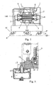
- the appended drawings represent a sealing head for wire heat treatment machines, which consists essentially of a frame 1 attached to a pressurized enclosure (not shown) traversed by a conveyor belt 100, by a pair of superposed horizontal rollers 2 and 3 which are pressed against the opposite faces of the conveyor belt 100 and by sealing means 4 and 5 to form a sealing between the rollers 2 and 3 and the frame 1, one at minus 2, horizontal rollers and the sealing means 4 and 5 being connected to corresponding displacement actuators 6 to 8.
- the actuators 6 to 8 of the horizontal roller or rollers 2 and / or 3 and sealing means 4 and 5 between the rollers 2 and 3 and the frame 1 are formed as actuators low pressure without piston , ie balloon or bellows type.
- these actuators 6 to 8 are actuators operating at a maximum operating pressure of the order of 8 bars.
- the actuators 6, which are intended to apply at least one of the two horizontal rollers on the conveyor belt 100 against the other horizontal roller 3, are advantageously double-acting diaphragm cylinders and are arranged on the frame 1, from and other said rollers horizontal and 2 and 3 and act on the drive shaft or guide of said horizontal rollers 2 and 3, at their ends, by means of sliding bearings 9 guided in the corresponding ends of the frame 1 and cooperating with push rods 10, connected at one end to said sliding bearing 9 and connected by their other end to the corresponding membrane of the actuator 6 ( figure 4 ).
- each actuator 6 in the form of two actuators of the balloon or single-acting bellows type, these two actuators each acting on either side, or of the support bearing of the shaft of the corresponding roller, or on a moving means connected to said bearing.
- the actuators 8 are advantageously bellows or balloon actuators and act on the sealing means 5 between the horizontal rollers 2 and 3 and the frame 1, which are constituted in the form of sealing plates, by means of a force transfer device in the form of a bent lever 16 pivotally mounted by an axis 16 'on the frame 1 and pivotally actuated by means of a transmission rod 17 having a return spring 17 '.
- each actuator 8 has the effect of moving the transmission rod 17 in the direction of a tilting actuation of the bent lever 16 about its axis 16 ', resulting in a corresponding transmission the force in the direction of the corresponding plate forming the sealing means 5 and the application under a predetermined pressure of said plate against the ends of the rollers 2 and 3.
- a bent lever 16 it is possible to performing an overdrive of the application force of the sealing means 5 by matching a transmission torque ratio corresponding to the ratio of the lever arms of the bent lever.
- the actuators 6 to 8 are advantageously pneumatic actuators.
- the use of such pneumatic actuators makes it possible, due to the compressibility of the air or a gas, to obtain damping of the vibrations and / or deformations. It is, however, also possible to make these actuators in the form of hydraulic actuators, oil or aqueous fluids, such as water or glycol, in particular.
- these actuators because of their constitution without sliding element outside their pressure chamber, are perfectly sealed, so that the risk of leakage of fluids are eliminated. Moreover, their operation at low pressure prevents any risk of overheating, which could be harmful for their operation.
- actuators 6 to 8 are advantageously commercial bellows flexible cylinders known by the name pneuride, of dimension 6 "x 1", and available in particular under the references PM31061 from NORGREN, 9109004 from PARKER or SP1536 from WEFORMA, and flexible bellows guns on the market known under the name pneuride, of size 4 "1/2 x 1", available in particular under the references PM31041 from NORGREN, 9109400 from PARKER or SP2334 from WEFORMA, and double-acting diaphragm cylinders, available in particular under the trade references KHGS from CEF and COD600-50 from REXROTH PARKER- BOSCH.
- the balloons constituting the actuators 6 to 8 can be made, depending on the conditions of use, of natural or synthetic rubber of the butyl, epichloro or nitrile type, these materials being optionally combined with a textile reinforcement.
- the damping effect will be limited to the deformability of the balloon, which is generally defined for a maximum operating pressure of 8 bar and an operating temperature of between -40 ° C. and + 130 ° C. depending on the material of the balloon. It is also possible to add to this material anti-UV agents for improving the resistance to ozone or to provide special protection on the surface of the bellows.
- the actuators 6 to 8 simultaneously act as actuators and air springs and allow, while being compact construction, obtaining a high power in a small footprint, and a high reliability and flexibility important operation.
- these actuators are maintenance-free, resistant to aggressive environments and their service life is very important.
- the bellows is protected from harmful side vibrations, even in case of asymmetrical wear of a blade or a sealing plate.
- the membranes being, moreover, in a known manner, protected against the projections of chemical agents by a stainless steel shield ensuring a perfect control of the stroke of the bellows, this protection is also effective against tears, scratches, nicks, the projections of particles and against shocks, as well as against the accidental overpressure of the fluid, the shielding preventing loosening.
- the various actuators 6 to 8 are each provided with a drain valve 6 'to 8' and are advantageously controlled automatically, either by means of a programmable controller 200, or by via a pneumatic automaton implementing elements of pneumatic logic, standard logic or electropneumatic logic acting on regulation valves 6 "to 8" arranged in the supply circuit of these actuators 6 to 8 ( figure 1 ).
- the implementation of a heat treatment machine with sealing heads provided with the actuators 6 and 8 is carried out according to a control method which consists, from an open treatment enclosure position, to temporarily closing the horizontal sealing rollers 2 and 3 around the conveyor belt 100, and then aligning the horizontal sealing rollers 2 and 3 by means of the sealing means 5, to definitively put in pressure the horizontal sealing rollers 2 and 3 against the conveyor belt 100, to then apply under pressure the sealing strips 12 of the sealing means 4 on the horizontal sealing rollers 2 and 3, to then apply under pressure the sealing means; 5 against the ends of the horizontal sealing rollers 2 and 3, then put the treatment chamber under pressure, subject to authorization to put en route delivered by contacts or sensors noting the closing of the various drain valves 6 'to 8' and the opening of the regulation valves 6 "to 8" assigned to the actuators 6 to 8, a pressure drop in the enclosure or an opening command of a sealing head causing a control shutdown of the regulation valves 6 "to 8" simultaneously with an opening of the emptying valve of the enclosure and the delivery of a restart prohibition signal
- the alignment of the horizontal sealing rollers 2 and 3 by means of the sealing means 5, after temporary closing of the horizontal sealing rollers 2 and 3 around the conveyor belt 100, is preferably carried out by a series of bets. under pressure and depressurization, actuators 8 acting on the sealing means 5.
- actuators 8 acting on the sealing means 5.
- the prediction of a detection of a pressure drop in the treatment machine makes it possible, thanks to the method described above, to prevent any unintentional opening of a sealing head following the emergency stop thus caused and ensures a process of access inside the enclosure of the machine perfectly controlled.
- sealing heads for wire heat treatment machines employing actuators that can be used simultaneously for the displacement of different moving elements and for the damping of the vibrations caused during operation, these actuators can be powered by different fluids, under a low pressure.
- the actuators according to the invention are not subject to any internal sealing problem and are of low cost.
- actuators are extremely robust, withstand aggressive and high temperature environments, are maintenance-free and can operate with angular and axial misalignments.
- the actuators 6 to 8 because of their constitution do not require specific guidance, can be easily and quickly mounted and dismounted, reassembly taking place without complex adjustment or special tools.
Landscapes
- Engineering & Computer Science (AREA)
- Textile Engineering (AREA)
- Actuator (AREA)
- Package Closures (AREA)
- Glass Compositions (AREA)
- Seal Device For Vehicle (AREA)
- Encapsulation Of And Coatings For Semiconductor Or Solid State Devices (AREA)
- Diaphragms And Bellows (AREA)
Claims (12)
- Dichtungskopf für Maschinen zur thermischen Behandlung von Fäden, mit einem Rahmen (1), der an einem druckhaltenden Gehäuse befestigt ist, welche von einem Transportband (100) durchquert wird, einem Paar von übereinander liegenden horizontalen Rollen (2 und 3), die gegen die gegenüberliegenden Flächen des Transportbandes (100) gepresst werden, und Dichtungsmitteln (4, 5), um einen dichten Verschluss zwischen den Rollen (2 und 3) und dem Gehäuse (1) zu bilden, wobei wenigstens eine der horizontalen Rollen (2 und 3) und die Dichtungsmittel (4 und 5) mit entsprechenden Betätigungseinrichtungen zum Verstellen (6 bis 8) verbunden sind, dadurch gekennzeichnet, dass die Betätigungseinrichtungen der horizontalen Rolle(n) (2 und/oder 3) und der Dichtungsmittel (4 und 5) zwischen den Rollen (2 und 3) und dem Gehäuse (1) in der Form von Niedrigdruck-Betätigungseinrichtungen ohne Kolben, d.h. der Ballonart oder der Blasebalgart, ausgebildet sind.
- Dichtungskopf nach dem Anspruch 1, dadurch gekennzeichnet, dass die Betätigungseinrichtungen (6 bis 8) solche Betätigungseinrichtungen sind, die unter einem maximalen Arbeitsdruck in der Größenordnung von 8 bar funktionieren.
- Dichtungskopf nach einem der Ansprüche 1 und 2, dadurch gekennzeichnet, dass die Betätigungseinrichtungen (6), die dazu dienen, wenigstens eine der beiden horizontalen Rollen über das Transportband (100) gegen die andere horizontale Rolle (3) zu drücken, doppelt wirkende Membranventile sind und an dem Rahmen (1) auf beiden Seiten der horizontalen Rollen (2 und 3) angeordnet sind und auf die Welle oder die Wellen zum Antrieb und zur Führung der horizontalen Rollen (2 und 3) auf der Höhe von deren Enden unter Zwischenschaltung von Gleitlagern (9), die in den entsprechenden Enden des Rahmens (1) geführt sind und mit Druckschäften (10) zusammenwirken, die an ihrem einen Ende an dem Gleitlager (9) befestigt und an ihrem anderen Ende mit der entsprechenden Membran der Betätigungseinrichtung (6) verbunden sind, wirken.
- Dichtungskopf nach einem der Ansprüche 1 und 2, dadurch gekennzeichnet, dass jede Betätigungseinrichtung (6) der horizontalen Rolle oder horizontalen Rollen (2 und 3) in der Form von zwei einfach wirkenden Betätigungseinrichtungen der Ballonart oder der Blasebalgart ausgebildet ist, wobei die beiden Betätigungseinrichtungen jeweils auf das Stützlager der Welle der entsprechenden Rolle oder auf ein Verstellmittel, das mit dem Lager verbunden ist, wirkt.
- Dichtungskopf nach einem der Ansprüche 1 und 2, dadurch gekennzeichnet, dass die Dichtungsmittel (4) zwischen den Rollen (2 und 3) und dem Gehäuse (1), die für jede Rolle (2 und 3) durch eine Dichtungslamelle (12) gebildet sind, die an einem Schwenklager (13) montiert ist, welches sich an dem Rahmen (1) über einen Längenanschlag für eine Schwenkbewegung (14) abstützt, jeweils mit der entsprechenden Betätigungseinrichtung (7) oder den entsprechenden Betätigungseinrichtungen (7) in der Form von Ballons oder Blasebalgs über eine Lastübertragungsstange (15) zusammenwirken, die an dem Gehäuse (1) zwischen der entsprechenden Betätigungseinrichtung (7) und dem Schwenklager (13) montiert und durch eine Rückstellfeder (15') beaufschlagt ist.
- Dichtungskopf nach einem der Ansprüche 1 und 2, dadurch gekennzeichnet, dass die Betätigungseinrichtungen (8) der Dichtungsmittel (5) Ballon- oder Blasebalg-Betätigungseinrichtungen sind und auf die Dichtungsmittel (5) zwischen den horizontalen Rollen (2 und 3) und dem Gehäuse (1), die in der Form von Dichtungsplatten ausgebildet sind, unter Zwischenschaltung einer Kraftübertragungsvorrichtung in der Form eines gekrümmten Hebels (16), der über eine Achse (16') an dem Gehäuse (1) schwenkbar montiert und schwenkend unter Zwischenschaltung einer Übertragungsstange (17) mit einer Rückstellfeder (17') betätigt wird, wirken.
- Dichtungskopf nach einem der Ansprüche 1 bis 6, dadurch gekennzeichnet, dass die Betätigungseinrichtungen (6 bis 8) pneumatische Betätigungseinrichtungen sind.
- Dichtungskopf nach einem der Ansprüche 1 bis 6, dadurch gekennzeichnet, dass die Betätigungseinrichtungen (6 bis 8) hydraulisch betätigte, ölbetätigte oder durch wässrige Flüssigkeiten wie Wasser oder Glycol betätigte Betätigungseinrichtungen sind.
- Dichtungskopf nach einem der Ansprüche 1 bis 8, dadurch gekennzeichnet, dass die unterschiedlichen Betätigungseinrichtungen (6 bis 8) jeweils mit einem Tellerventil (6' bis 8') versehen und automatisch entweder über einen programmierbaren Automat (200) oder über einen pneumatischen Automat, der pneumatische logische Elemente, logische Standardelemente oder logische elektropneumatische Elemente, die auf Einstellventile (6'' bis 8'') wirken, welche in dem Versorgungskreis der Betätigungseinrichtungen (6 bis 8) vorgesehen sind, betätigt, gesteuert werden.
- Verfahren zur Steuerung einer Maschine für die thermische Behandlung mit Dichtungsköpfen, welche mit Betätigungseinrichtungen (6 bis 8) versehen sind, gemäß den Ansprüchen 5 bis 9, dadurch gekennzeichnet, dass sie ausgesend von einer offenen Position des Arbeitsraums darin besteht, dass eine provisorische Schließung der horizontalen Dichtungsrollen (2 und 3) um das Transportband (100) bewirkt wird, dann eine Ausrichtung der horizontalen Dichtungsrollen (2 und 3) über die Dichtungsmittel (5), die in der Form von Dichtungsplatten vorgesehen sind, realisiert wird, dass die horizontalen Dichtungsrollen (2 und 3) definitiv gegen das Transportband (100) gedrückt werden, anschließend die Dichtungslamellen (12) der Dichtungsmittel (4) gegen die horizontalen Dichtungsrollen (2 und 3) gedrückt werden, anschließend die Dichtungsmittel (5), welche in der Form von Dichtungsplatten vorgesehen sind, gegen die Enden der horizontalen Dichtungsrollen (2 und 3) gedrückt werden, dann unter der Voraussetzung einer Autorisation zur Betätigung, die durch Kontakte oder Aufnehmer geliefert wird, welche das Schließen der unterschiedlichen Tellerventile (6' bis 8') und den offenen Zustand der Einstellventile (6'' bis 8''), die den Betätigungseinrichtungen (6 bis 8) zugeordnet sind, der Arbeitsraum unter Druck gesetzt wird, wobei ein Druckabfall in dem Raum oder ein Befehl zum Öffnen eines Dichtungskopfes zu einem Anhalten der Steuerung der Einstellventile (6" bis 8") und gleichzeitig zu einem Öffnen des Tellerventils des Raums und zum Abgeben eines Signals, das das Wiederinbetriebsetzen verbietet, führt, wobei die Betätigungseinrichtungen (8) der Dichtungsmittel (5), die in der Form von Dichtungsplatten vorgesehen sind, die Betätigungseinrichtungen (7) für die Dichtungslamellen (12) der Dichtungsmittel und die Betätigungseinrichtungen (6) zur Verstellung der horizontalen Dichtungsrolle oder der horizontalen Dichtungsrollen (2) und/oder (3) anschließend drucklos gestellt werden, um wieder an einer Öffnungsposition der Maschine vor einem neuen Behandlungszyklus anzukommen.
- Steuerverfahren nach dem Anspruch 10, dadurch gekennzeichnet, dass die provisorische Schließung der horizontalen Dichtungsrollen (2 und 3) um das Transportband (100) durch eine einfache Drucklosstellung der doppelt wirkenden Betätigungseinrichtungen (6) in der Weise bewirkt wird, dass die obere Rolle (2) sich unter ihrem eigenen Gewicht in Kontakt mit dem Transportband absenkt.
- Steuerverfahren nach dem Anspruch 10, dadurch gekennzeichnet, dass die Ausrichtung der horizontalen Dichtungsrollen (2 und 3) über die Dichtungsmittel (5), die in der Form von Dichtungsplatten gebildet sind, nach dem provisorischen Schließen der horizontalen Dichtungsrollen (2 und 3) um das Transportband (100) bewirkt wird, indem eine Folge von Unterdrucksetzungen und Drucklosstellungen der Betätigungseinrichtungen (8), welche auf die Dichtungsmittel (5) in der Form von Dichtungsplatten wirken, bewirkt wird.
Applications Claiming Priority (1)
| Application Number | Priority Date | Filing Date | Title |
|---|---|---|---|
| FR0508987A FR2890084B1 (fr) | 2005-09-01 | 2005-09-01 | Tete d'etancheite |
Publications (3)
| Publication Number | Publication Date |
|---|---|
| EP1760179A2 EP1760179A2 (de) | 2007-03-07 |
| EP1760179A3 EP1760179A3 (de) | 2008-05-21 |
| EP1760179B1 true EP1760179B1 (de) | 2011-09-07 |
Family
ID=36481431
Family Applications (1)
| Application Number | Title | Priority Date | Filing Date |
|---|---|---|---|
| EP06360033A Active EP1760179B1 (de) | 2005-09-01 | 2006-08-02 | Dichtungsvorrichtung |
Country Status (4)
| Country | Link |
|---|---|
| EP (1) | EP1760179B1 (de) |
| CN (1) | CN1924152B (de) |
| AT (1) | ATE523621T1 (de) |
| FR (1) | FR2890084B1 (de) |
Families Citing this family (1)
| Publication number | Priority date | Publication date | Assignee | Title |
|---|---|---|---|---|
| CN108611794B (zh) * | 2018-07-02 | 2020-06-30 | 吉安新华南户外用品有限公司 | 一种纺织布料拉绒加工设备及布料拉绒加工工艺 |
Family Cites Families (1)
| Publication number | Priority date | Publication date | Assignee | Title |
|---|---|---|---|---|
| FR2652829B1 (fr) * | 1989-10-11 | 1992-02-07 | Superba Sa | Tete d'etancheite pour une entree ou une sortie d'une enceinte de traitement de fils textiles. |
-
2005
- 2005-09-01 FR FR0508987A patent/FR2890084B1/fr not_active Expired - Fee Related
-
2006
- 2006-08-02 AT AT06360033T patent/ATE523621T1/de not_active IP Right Cessation
- 2006-08-02 EP EP06360033A patent/EP1760179B1/de active Active
- 2006-08-25 CN CN2006101214588A patent/CN1924152B/zh not_active Expired - Fee Related
Also Published As
| Publication number | Publication date |
|---|---|
| FR2890084A1 (fr) | 2007-03-02 |
| EP1760179A3 (de) | 2008-05-21 |
| CN1924152B (zh) | 2011-11-16 |
| EP1760179A2 (de) | 2007-03-07 |
| CN1924152A (zh) | 2007-03-07 |
| FR2890084B1 (fr) | 2007-10-12 |
| ATE523621T1 (de) | 2011-09-15 |
Similar Documents
| Publication | Publication Date | Title |
|---|---|---|
| EP3686427B1 (de) | Pumpe für flüssiges produkt, die eine dichtungsvorrichtung umfasst, und sprühanlage, die eine solche pumpe umfasst | |
| CA2270579A1 (fr) | Dispositif de maintien en position de la tige d'un verin hydraulique | |
| FR2470321A1 (fr) | Vanne | |
| EP3875759B1 (de) | Vorrichtung und verfahren zum fördern von viskosem material | |
| EP0189345B1 (de) | Vorrichtung zur Zusammenfügung durch Kalandern mindestens einer Glasschicht und mindestens einer Kunststoffolie | |
| EP0461943A2 (de) | Verdichtungsvorrichtung, insbesondere zur Druckfüllung eines Behälters | |
| FR2953594A1 (fr) | Dispositif de test pour separateur souple | |
| EP0441701A1 (de) | Flexible rohrförmige Struktur mit einer Verstärkungseinlage | |
| EP1760179A2 (de) | Dichtungsvorrichtung | |
| CA3127596A1 (fr) | Systeme de pompage et installation de refoulement de fluide | |
| WO1994007099A1 (fr) | Dispositif de transfert de pieces de bois dans un four de sechage par micro-ondes | |
| FR2887595A1 (fr) | Dispositif actionne par un fluide pour mettre en oeuvre un mecanisme pendant une urgence | |
| EP0128096A1 (de) | Antrieb mit pneumatischem Druckspeicher, insbesondere für Ventile | |
| EP2927547B1 (de) | Mini-schnellverschluss-magnetventil | |
| FR3066720B1 (fr) | Module de decoupe pour une tete de placement d'un ruban de fibres impregnees, tete de placement et dispositif de placement d'un tel ruban de fibres | |
| EP1762646B1 (de) | Dichtungsvorrichtung für Maschinen zur Wärmebehandlung von Garnen | |
| EP2420348A1 (de) | Vorrichtung zur linearen Betätigung von mehreren Zylindern und Kontrollverfahren einer solchen Vorrichtung | |
| FR3065525A1 (fr) | Appareil de controle a piston pour le calibrage et/ou l'etalonnage d'un appareil de mesure de debit | |
| WO2003059609A1 (fr) | Machine a fabriquer des coussins d'air pour l'emballage a partir d'un film tubulaire dispose sur une bobine | |
| FR3132515A1 (fr) | Système d’enroulement d’un lien tel qu’une ficelle et table de déroulage utilisant un tel système d’enroulement | |
| EP1226886A1 (de) | Einrichtung zum Fördern und Führen eines Metallbandes | |
| BE1013747A3 (fr) | Dispositif pour creer un mouvement dans un liquide. | |
| FR2985791A1 (fr) | Dispositif de detection de rupture d'une membrane d'une pompe a actionnement hydraulique, procede de montage d'un tel dispositif sur une pompe, et pompe equipee d'un tel dispositif | |
| FR2562054A1 (fr) | Procede de mise en oeuvre sequentielle automatique d'un event a commande pneumatique et ensemble permettant la mise en oeuvre de ce procede | |
| FR2790770A1 (fr) | Dispositif de securite de detection d'enroulements autour des rouleaux de pression superieurs et/ou des cylindres inferieurs d'une craqueuse |
Legal Events
| Date | Code | Title | Description |
|---|---|---|---|
| PUAI | Public reference made under article 153(3) epc to a published international application that has entered the european phase |
Free format text: ORIGINAL CODE: 0009012 |
|
| AK | Designated contracting states |
Kind code of ref document: A2 Designated state(s): AT BE BG CH CY CZ DE DK EE ES FI FR GB GR HU IE IS IT LI LT LU LV MC NL PL PT RO SE SI SK TR |
|
| AX | Request for extension of the european patent |
Extension state: AL BA HR MK YU |
|
| PUAL | Search report despatched |
Free format text: ORIGINAL CODE: 0009013 |
|
| AK | Designated contracting states |
Kind code of ref document: A3 Designated state(s): AT BE BG CH CY CZ DE DK EE ES FI FR GB GR HU IE IS IT LI LT LU LV MC NL PL PT RO SE SI SK TR |
|
| AX | Request for extension of the european patent |
Extension state: AL BA HR MK RS |
|
| 17P | Request for examination filed |
Effective date: 20080821 |
|
| 17Q | First examination report despatched |
Effective date: 20081010 |
|
| AKX | Designation fees paid |
Designated state(s): AT BE BG CH CY CZ DE DK EE ES FI FR GB GR HU IE IS IT LI LT LU LV MC NL PL PT RO SE SI SK TR |
|
| GRAP | Despatch of communication of intention to grant a patent |
Free format text: ORIGINAL CODE: EPIDOSNIGR1 |
|
| GRAS | Grant fee paid |
Free format text: ORIGINAL CODE: EPIDOSNIGR3 |
|
| GRAA | (expected) grant |
Free format text: ORIGINAL CODE: 0009210 |
|
| REG | Reference to a national code |
Ref country code: GB Ref legal event code: FG4D Free format text: NOT ENGLISH |
|
| REG | Reference to a national code |
Ref country code: CH Ref legal event code: EP |
|
| REG | Reference to a national code |
Ref country code: IE Ref legal event code: FG4D Free format text: LANGUAGE OF EP DOCUMENT: FRENCH |
|
| REG | Reference to a national code |
Ref country code: DE Ref legal event code: R096 Ref document number: 602006024168 Country of ref document: DE Effective date: 20111124 |
|
| REG | Reference to a national code |
Ref country code: NL Ref legal event code: VDEP Effective date: 20110907 |
|
| PG25 | Lapsed in a contracting state [announced via postgrant information from national office to epo] |
Ref country code: SE Free format text: LAPSE BECAUSE OF FAILURE TO SUBMIT A TRANSLATION OF THE DESCRIPTION OR TO PAY THE FEE WITHIN THE PRESCRIBED TIME-LIMIT Effective date: 20110907 Ref country code: LT Free format text: LAPSE BECAUSE OF FAILURE TO SUBMIT A TRANSLATION OF THE DESCRIPTION OR TO PAY THE FEE WITHIN THE PRESCRIBED TIME-LIMIT Effective date: 20110907 Ref country code: FI Free format text: LAPSE BECAUSE OF FAILURE TO SUBMIT A TRANSLATION OF THE DESCRIPTION OR TO PAY THE FEE WITHIN THE PRESCRIBED TIME-LIMIT Effective date: 20110907 |
|
| LTIE | Lt: invalidation of european patent or patent extension |
Effective date: 20110907 |
|
| PG25 | Lapsed in a contracting state [announced via postgrant information from national office to epo] |
Ref country code: GR Free format text: LAPSE BECAUSE OF FAILURE TO SUBMIT A TRANSLATION OF THE DESCRIPTION OR TO PAY THE FEE WITHIN THE PRESCRIBED TIME-LIMIT Effective date: 20111208 Ref country code: CY Free format text: LAPSE BECAUSE OF FAILURE TO SUBMIT A TRANSLATION OF THE DESCRIPTION OR TO PAY THE FEE WITHIN THE PRESCRIBED TIME-LIMIT Effective date: 20110907 Ref country code: AT Free format text: LAPSE BECAUSE OF FAILURE TO SUBMIT A TRANSLATION OF THE DESCRIPTION OR TO PAY THE FEE WITHIN THE PRESCRIBED TIME-LIMIT Effective date: 20110907 Ref country code: SI Free format text: LAPSE BECAUSE OF FAILURE TO SUBMIT A TRANSLATION OF THE DESCRIPTION OR TO PAY THE FEE WITHIN THE PRESCRIBED TIME-LIMIT Effective date: 20110907 Ref country code: LV Free format text: LAPSE BECAUSE OF FAILURE TO SUBMIT A TRANSLATION OF THE DESCRIPTION OR TO PAY THE FEE WITHIN THE PRESCRIBED TIME-LIMIT Effective date: 20110907 |
|
| REG | Reference to a national code |
Ref country code: AT Ref legal event code: MK05 Ref document number: 523621 Country of ref document: AT Kind code of ref document: T Effective date: 20110907 |
|
| REG | Reference to a national code |
Ref country code: IE Ref legal event code: FD4D |
|
| PG25 | Lapsed in a contracting state [announced via postgrant information from national office to epo] |
Ref country code: IE Free format text: LAPSE BECAUSE OF FAILURE TO SUBMIT A TRANSLATION OF THE DESCRIPTION OR TO PAY THE FEE WITHIN THE PRESCRIBED TIME-LIMIT Effective date: 20110907 Ref country code: CZ Free format text: LAPSE BECAUSE OF FAILURE TO SUBMIT A TRANSLATION OF THE DESCRIPTION OR TO PAY THE FEE WITHIN THE PRESCRIBED TIME-LIMIT Effective date: 20110907 Ref country code: SK Free format text: LAPSE BECAUSE OF FAILURE TO SUBMIT A TRANSLATION OF THE DESCRIPTION OR TO PAY THE FEE WITHIN THE PRESCRIBED TIME-LIMIT Effective date: 20110907 Ref country code: IS Free format text: LAPSE BECAUSE OF FAILURE TO SUBMIT A TRANSLATION OF THE DESCRIPTION OR TO PAY THE FEE WITHIN THE PRESCRIBED TIME-LIMIT Effective date: 20120107 |
|
| PG25 | Lapsed in a contracting state [announced via postgrant information from national office to epo] |
Ref country code: RO Free format text: LAPSE BECAUSE OF FAILURE TO SUBMIT A TRANSLATION OF THE DESCRIPTION OR TO PAY THE FEE WITHIN THE PRESCRIBED TIME-LIMIT Effective date: 20110907 Ref country code: PL Free format text: LAPSE BECAUSE OF FAILURE TO SUBMIT A TRANSLATION OF THE DESCRIPTION OR TO PAY THE FEE WITHIN THE PRESCRIBED TIME-LIMIT Effective date: 20110907 Ref country code: NL Free format text: LAPSE BECAUSE OF FAILURE TO SUBMIT A TRANSLATION OF THE DESCRIPTION OR TO PAY THE FEE WITHIN THE PRESCRIBED TIME-LIMIT Effective date: 20110907 Ref country code: EE Free format text: LAPSE BECAUSE OF FAILURE TO SUBMIT A TRANSLATION OF THE DESCRIPTION OR TO PAY THE FEE WITHIN THE PRESCRIBED TIME-LIMIT Effective date: 20110907 Ref country code: PT Free format text: LAPSE BECAUSE OF FAILURE TO SUBMIT A TRANSLATION OF THE DESCRIPTION OR TO PAY THE FEE WITHIN THE PRESCRIBED TIME-LIMIT Effective date: 20120109 |
|
| PLBE | No opposition filed within time limit |
Free format text: ORIGINAL CODE: 0009261 |
|
| STAA | Information on the status of an ep patent application or granted ep patent |
Free format text: STATUS: NO OPPOSITION FILED WITHIN TIME LIMIT |
|
| PG25 | Lapsed in a contracting state [announced via postgrant information from national office to epo] |
Ref country code: DK Free format text: LAPSE BECAUSE OF FAILURE TO SUBMIT A TRANSLATION OF THE DESCRIPTION OR TO PAY THE FEE WITHIN THE PRESCRIBED TIME-LIMIT Effective date: 20110907 |
|
| 26N | No opposition filed |
Effective date: 20120611 |
|
| REG | Reference to a national code |
Ref country code: DE Ref legal event code: R097 Ref document number: 602006024168 Country of ref document: DE Effective date: 20120611 |
|
| REG | Reference to a national code |
Ref country code: CH Ref legal event code: PL |
|
| PG25 | Lapsed in a contracting state [announced via postgrant information from national office to epo] |
Ref country code: MC Free format text: LAPSE BECAUSE OF NON-PAYMENT OF DUE FEES Effective date: 20120831 |
|
| PG25 | Lapsed in a contracting state [announced via postgrant information from national office to epo] |
Ref country code: ES Free format text: LAPSE BECAUSE OF FAILURE TO SUBMIT A TRANSLATION OF THE DESCRIPTION OR TO PAY THE FEE WITHIN THE PRESCRIBED TIME-LIMIT Effective date: 20111218 Ref country code: CH Free format text: LAPSE BECAUSE OF NON-PAYMENT OF DUE FEES Effective date: 20120831 Ref country code: LI Free format text: LAPSE BECAUSE OF NON-PAYMENT OF DUE FEES Effective date: 20120831 |
|
| PG25 | Lapsed in a contracting state [announced via postgrant information from national office to epo] |
Ref country code: BG Free format text: LAPSE BECAUSE OF FAILURE TO SUBMIT A TRANSLATION OF THE DESCRIPTION OR TO PAY THE FEE WITHIN THE PRESCRIBED TIME-LIMIT Effective date: 20111207 |
|
| PGFP | Annual fee paid to national office [announced via postgrant information from national office to epo] |
Ref country code: FR Payment date: 20130902 Year of fee payment: 8 |
|
| PG25 | Lapsed in a contracting state [announced via postgrant information from national office to epo] |
Ref country code: LU Free format text: LAPSE BECAUSE OF NON-PAYMENT OF DUE FEES Effective date: 20120802 |
|
| PG25 | Lapsed in a contracting state [announced via postgrant information from national office to epo] |
Ref country code: HU Free format text: LAPSE BECAUSE OF FAILURE TO SUBMIT A TRANSLATION OF THE DESCRIPTION OR TO PAY THE FEE WITHIN THE PRESCRIBED TIME-LIMIT Effective date: 20060802 |
|
| REG | Reference to a national code |
Ref country code: FR Ref legal event code: ST Effective date: 20150430 |
|
| PG25 | Lapsed in a contracting state [announced via postgrant information from national office to epo] |
Ref country code: FR Free format text: LAPSE BECAUSE OF NON-PAYMENT OF DUE FEES Effective date: 20140901 |
|
| PGFP | Annual fee paid to national office [announced via postgrant information from national office to epo] |
Ref country code: IS Payment date: 20170519 Year of fee payment: 8 Ref country code: IT Payment date: 20170809 Year of fee payment: 12 |
|
| GBPC | Gb: european patent ceased through non-payment of renewal fee |
Effective date: 20180802 |
|
| PG25 | Lapsed in a contracting state [announced via postgrant information from national office to epo] |
Ref country code: IT Free format text: LAPSE BECAUSE OF NON-PAYMENT OF DUE FEES Effective date: 20180802 |
|
| PG25 | Lapsed in a contracting state [announced via postgrant information from national office to epo] |
Ref country code: GB Free format text: LAPSE BECAUSE OF NON-PAYMENT OF DUE FEES Effective date: 20180802 |
|
| PGFP | Annual fee paid to national office [announced via postgrant information from national office to epo] |
Ref country code: TR Payment date: 20230725 Year of fee payment: 18 |
|
| PGFP | Annual fee paid to national office [announced via postgrant information from national office to epo] |
Ref country code: DE Payment date: 20230808 Year of fee payment: 18 Ref country code: BE Payment date: 20230822 Year of fee payment: 18 |
|
| REG | Reference to a national code |
Ref country code: DE Ref legal event code: R119 Ref document number: 602006024168 Country of ref document: DE |
|
| REG | Reference to a national code |
Ref country code: BE Ref legal event code: MM Effective date: 20240831 |
|
| PG25 | Lapsed in a contracting state [announced via postgrant information from national office to epo] |
Ref country code: DE Free format text: LAPSE BECAUSE OF NON-PAYMENT OF DUE FEES Effective date: 20250301 |
|
| PG25 | Lapsed in a contracting state [announced via postgrant information from national office to epo] |
Ref country code: BE Free format text: LAPSE BECAUSE OF NON-PAYMENT OF DUE FEES Effective date: 20240831 |