EP1760180A2 - Chambre d'aspiration pour un distributeur pour le traitement par jets d'eau de tissus - Google Patents
Chambre d'aspiration pour un distributeur pour le traitement par jets d'eau de tissus Download PDFInfo
- Publication number
- EP1760180A2 EP1760180A2 EP06015183A EP06015183A EP1760180A2 EP 1760180 A2 EP1760180 A2 EP 1760180A2 EP 06015183 A EP06015183 A EP 06015183A EP 06015183 A EP06015183 A EP 06015183A EP 1760180 A2 EP1760180 A2 EP 1760180A2
- Authority
- EP
- European Patent Office
- Prior art keywords
- suction
- suction chamber
- water
- perforated
- air supply
- Prior art date
- Legal status (The legal status is an assumption and is not a legal conclusion. Google has not performed a legal analysis and makes no representation as to the accuracy of the status listed.)
- Granted
Links
Images


Classifications
-
- D—TEXTILES; PAPER
- D04—BRAIDING; LACE-MAKING; KNITTING; TRIMMINGS; NON-WOVEN FABRICS
- D04H—MAKING TEXTILE FABRICS, e.g. FROM FIBRES OR FILAMENTARY MATERIAL; FABRICS MADE BY SUCH PROCESSES OR APPARATUS, e.g. FELTS, NON-WOVEN FABRICS; COTTON-WOOL; WADDING ; NON-WOVEN FABRICS FROM STAPLE FIBRES, FILAMENTS OR YARNS, BONDED WITH AT LEAST ONE WEB-LIKE MATERIAL DURING THEIR CONSOLIDATION
- D04H18/00—Needling machines
- D04H18/04—Needling machines with water jets
-
- D—TEXTILES; PAPER
- D06—TREATMENT OF TEXTILES OR THE LIKE; LAUNDERING; FLEXIBLE MATERIALS NOT OTHERWISE PROVIDED FOR
- D06C—FINISHING, DRESSING, TENTERING OR STRETCHING TEXTILE FABRICS
- D06C29/00—Finishing or dressing, of textile fabrics, not provided for in the preceding groups
Definitions
- the invention relates to a suction chamber for a water beam for the jet exposure of fabrics, Gewebgewirkbahnen or nonwovens, consisting of staple fibers, continuous filaments or cellulose fibers also from several layers or mixtures and provided on the lower side of the suction perforated suction for the extraction of water spray.
- a water bar for the water needling of fabrics ( WO 01/40562 A1 ), which is associated with a cover groove, which is mounted from an upper support and a cover arranged below it with a porous bottom so that a suction channel can be formed.
- a suction opening and a horizontal porous cover plate are arranged on one side of the water jet.
- the invention is based on the object that a water jet emerging from the water jet in its direction over the entire length and / or width of the water bar is not affected by splashing water and the water mist resulting from the spraying and the usual drop formation is excluded at the bottom of the water bar.
- the suction surface is arranged to extend inclined and extending from an upper portion near the water bar and / or a drip edge to a lower portion of the suction chamber.
- the perforated suction surface has openings with different sized cross-sectional area.
- a uniform suction pressure is ensured over the entire suction surface of the suction device.
- cross-sectional areas of the openings are increasingly larger starting from the drip edge downwards.
- cross-sectional areas of the openings, starting from the drip edge are continuously larger or progressively larger in uniform steps.
- the distance between the individual openings is the same or different.
- an angle is formed by a tangential of a screen roller and the perforated suction surface, which is between 5 ° and 25 °, in particular between 6 ° and 15 °, wherein the openings of the suction surface on the inner side facing a water jet an open area of about 3% to 8% preferably 5% and on the outer side of about 10% to 25% preferably 20%.
- the water beam and / or the suction chamber is associated with an air supply device which is equipped with at least one outlet opening, which is provided in the region of the water bar.
- an air supply device which is equipped with at least one outlet opening, which is provided in the region of the water bar.
- the air supply device has an air supply channel, which is formed by a distance of 1 to 15 mm, preferably 3 to 10 mm and in particular 3 mm and 6 mm between an outer side of the water bar and an outside of the suction chamber facing the water bar is.
- the air supply channel is formed by an air gap between the water bar and the suction chamber. Therefore, in the Essentially no additional components needed.
- the air supply duct can also be realized, for example, via installed hoses.
- the air supply to the water jet can be carried out such that the air supply device is associated with a blower for generating a slight overpressure.
- the dry air is actively supplied to the water jet and the air supply to the water jet is not exclusively due to the above-described suction effect by the water jet, but also by a slight overpressure within the air supply duct.
- the outlet opening of the air supply device extends approximately over the entire length of the water bar. This ensures in a simple manner that supplied over the entire length of the water bar of the water jet with dry air and thus is not affected by fine water droplets or spray.
- the outlet opening of the air supply device is aligned so that the air flow impinges approximately perpendicular to the water jet emerging from the water bar.
- the exiting water jet is focused in a simple manner and directed spray water in the direction of the water jet.
- the air supply device or the air gap is at least partially provided between the water bar and the outlet opening of the suction chamber or along the outside of the water bar and runs parallel to this in the region of a lower side of the water bar.
- the suction chamber and / or the air supply device is arranged in each case symmetrically to both sides of the water bar and / or the water jet or are. Splashing water reflected by the fabric can thus be sucked off in the running direction of the fabric after the impingement of the water jet or optionally also in front of the water jet.
- the independent supply of dry air via the air supply device can take place both before and behind the water jet.
- the arrangement of the suction chamber and the air supply device can be made independently of each other in any combination.
- the openings of the perforated suction on the inner side facing the water jet are preferably formed as parallel slots having a length between 1 mm and 10 mm and a width between 0.1 mm and 3 mm, wherein the The openings provided on the outer side of the perforated suction surface are preferably formed angularly with a length between 1 mm and 10 mm and a width between 0.1 mm and 3 mm.
- the openings have differently shaped cross-sectional areas and are formed oval, polygonal, angular or elongated slots. Such an arrangement, as well as the shape of the openings, ensures that the drops, as they travel along the surface towards the lower portion of the suction surface, are forced to pass through the openings and can not easily bypass them. Particularly effective are the angularly shaped openings of the perforated suction in that area with a relatively large open area.
- an air displacement body is positioned so that a uniform suction effect over the entire width and / or length of the perforated suction is ensured because the suction takes place on one side.
- the arrangement of the air displacement body become air currents adjusted within the suction chamber as needed. A special flexibility is achieved when the air displacement body is mounted variable in height and inclination.
- the air displacement body above the perforated suction surface in particular above the suction surface with a relatively large open area and the perforated suction so narrows that a maximum air flow of, for example, 2 m / s is achieved on the outside of the perforated suction.
- the air displacement body extends approximately over the entire width and / or length of the suction chamber and that the air displacement body is an approximately rectangular body, in particular a housing which extends in the direction of the suction chamber and in this Direction inclined. As a result, a uniform suction power is ensured over the entire surface of the suction device.
- the air displacement body has a lower side, which encloses in the longitudinal direction of the suction chamber with its underside an angle which is between 1 ° and 30 °, in particular between 1 ° and 5 °, wherein the gap between the air displacement body and the perforated suction in the direction of the suction device is narrower.
- the air displacement body ends with its one end or its side wall in the region of a suction device connected to the suction chamber.
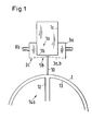
- 1a denotes a water beam, from which a water jet 10 exits through nozzle openings, not shown in the drawing and impinges on a fabric backing 13 of a screen drum or screen roller 14a zoom introduced tissue, a tissue web or webs 2.
- the water is discharged for the most part via a Wasserab technologicalvorraum 12 of the screen roller 14a.
- a suction device or suction chamber 5a which has on its lower side 5b an inclined perforated suction surface 3a, b with openings 3c, so that the appearance of the water jet 10 on tissue, a tissue web or webs 2 resulting Splashing water is passed to the underside of the suction chamber 5b and can then be completely sucked off by the suction chamber 5a.
- the water droplets occurring at the bottom of the water bar 1a be avoided and no longer drain on the fabric, the tissue web or the webs 2.
- the suction chamber 5a is arranged symmetrically to both sides of the water bar 1 a.
- a negative pressure which is provided by a not shown in the drawing pump, which is connected via a suction hose 8b with the suction chamber 5a.
- Fig. 2 shows a further embodiment of the suction chamber 5a for the water beam 1 a for jet exposure of fabrics, tissue webs or webs 2 with provided on the lower side 5b of the suction 5a perforated suction 3a and 3b for the suction of water spray 4.
- the perforated suction 3a 3b is inclined so as to extend from an upper portion 6b close to the water bar 1a and / or a drip edge 6a to a lower portion 6c of the suction chamber 5a.
- the first portion 3a of the perforated suction surface has a relatively small open area, while the second portion 3b of the perforated suction area has a relatively large area.
- the suction chamber can also be formed without the drip edge.
- the openings 3c provided in the perforated suction surface have a smaller average in the section 3a than the openings 3c in the section 3b. In this way, an approximately equal suction pressure is generated on the inner upper side of the suction surface 3a or 3b so that the spray water impinging on the fabric, the fabric weft web or the webs 2 can be readily sucked off. Furthermore, the water droplets traveling downward due to gravity can be completely sucked into the suction chamber 5a through the larger openings 3c in the lower area of the suction surface 6c.
- the distance between the individual openings 3c may be the same or different.
- the cross-sectional areas of the openings 3c starting from the drip edge 6a become progressively larger in the direction of the suction chamber 5a or a side 5c of the suction chamber 5a facing away from the water beam 1a.
- the cross-sectional areas of the openings 3c, starting from the drip edge 6a continuously or in uniform steps can be increasingly larger.
- the second embodiment is located on the outer periphery of the screen roller 14a on a tangential 14b.
- the tangential 14b encloses an angle ⁇ with the lower surface of the suction surface 3a and 3b.
- the angle ⁇ may be between 5 ° and 25 °, but preferably between 6 ° and 15 °.
- the openings 3 c of the suction surface 3 a, 3 b on the inner side 3 a facing the water jet 10 of the water bar 1 a make an open area of about 3% to 8%, preferably 5%, and an open area of about 10% to 25 on the outer side % preferably from 20% about 20%.
- 2 is located on the right side of the water bar 1a, the suction chamber 5a, which may be formed as an approximately rectangular box and is received via the spray water 4.
- the water bar 1 a and the suction 5a is associated with an air supply 11 a, which has an air supply duct 11 b, which ends in the region of the lower side 1 b of the water bar 1 a, wherein an outlet opening 11 c of the air supply channel 11 b in the vicinity of the water jet 10 is located.
- the air supply passage 11b is formed substantially by an outside of the water bar 1c and a left outside 5d of the suction chamber 5a.
- the air supply channel 11b extends approximately parallel to the outside of the water bar 1 a and the lower side 1 b of the water bar 1 a.
- the drip edge 6 a associated with the suction chamber 5 a. At the drip edge 6a only very fine drops of water can form, which can do no further damage when they fall down.
- the dry air introduced via the air supply duct 11b of the air supply device 11a to the water jet 10 has the advantage that it does not influence the water jet 10 in its direction.
- the water jet 10 is thus not influenced by very fine water droplets or mist and can be projected particularly focused on the tissue, the tissue web or the webs 2.
- the dry air via the air supply channel 11 b introduced by the water jet 10 intrinsic suction effect.
- the dry air can also be actively supplied to the water jet 10 in a further embodiment, which is not shown in the drawing, if necessary by means of a blower.
- the suction chamber 5a can be arranged symmetrically on both sides of the water bar 1a (see also Fig. 1).
- the air supply device 11a can be arranged symmetrically on both sides of the water bar 1a.
- the cross-sectional area of the air supply device 11a or of the air supply channel 11b is between 3 and 15 mm, preferably between 5 and 10 mm, in particular between 7 and 8 mm in size.
- the air supply duct 11 b of the air supply device 11 a is in this embodiment substantially by a distance of 1 to 15 mm, preferably 3 to 10 mm and in particular 3 and 6 mm between an outer side of the water bar 1 c and the water bar facing the outside of the suction 5d formed.
- the air supply channel 11 b may be configured in a drawing variant, not shown, by hoses or similar air supply means.
- the outlet opening 11 c extends approximately over the entire width of the water bar 1 a.
- the outlet opening 11 c is further aligned so that the exiting air jet occurs approximately perpendicular to the emerging from the water bar 1 a water jet 10.
- the openings 3c of the perforated suction surface on the side 3a facing the water jet 10 may be formed as elongated approximately parallel slots having a length between 1 mm and 10 mm and a width A between 0.1 mm and 3 mm , Further, it is possible that the slits provided on the outer side 3b of the perforated suction surface are preferably formed angularly with a length between 1 mm and 10 mm and a width B between 0.1 mm and 3 mm. Depending on the embodiment, the slots may also have a linear or a wave-shaped course. All of these design variants of the openings 3c have the aim of absorbing the water droplets of the spray water 4 running along the perforated suction surface as efficiently as possible. It should be prevented in particular that the water droplets of the spray water 4 can pass between the openings 3c.
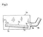
- an air displacement body 7a can be arranged in the suction chamber 5a, which can have different shapes.
- the air displacement body 7a is formed as a hollow body and is bounded by two parallel side walls 7c and 7d.
- a lower side 7b of the displacement body 7a extends approximately parallel to the inner surface of the perforated suction surface 3a, 3b.
- the air displacement body 7a is located above the perforated suction surface 3a, 3b, in particular above the suction surface with a relatively large open area 3b, so that the perforated suction surface 3a, 3b is narrowed such that a maximum air flow of, for example, 2 m / s is achieved on the outside of the perforated suction 3b.
- the air displacement body 7a extends over the entire width and / or length of the suction chamber 5a.
- the air displacement body 7a may be variably mounted in a further advantageous embodiment, not shown in the drawing, in its height and inclination.
- the underside 7b of the displacer 7a extends in the same direction as the suction surface 3a and 3b and thus includes an angle ⁇ not shown in the drawing between 5 ° and 30 °.
- the air displacement body may also include, with its lower side 7b, opposite the inner surface of the perforated suction surface 3a, 3b, an angle ⁇ which is between 1 ° and 30 ° and between 1 ° and 5 °, respectively. the gap between the air displacement body 7a and the perforated suction surface 3a, 3b becoming narrower in the direction of a suction device 8a.
- suction device consisting of a connecting piece 8a and a suction hose 8b, via which the spray water taken up by the suction chamber 5a is discharged and the negative pressure is generated in the same.
- the interior of the suction chamber 5 a is accessible via a supply flap 9.
Landscapes
- Engineering & Computer Science (AREA)
- Textile Engineering (AREA)
- Nonwoven Fabrics (AREA)
- Treatment Of Fiber Materials (AREA)
- Perforating, Stamping-Out Or Severing By Means Other Than Cutting (AREA)
Priority Applications (2)
| Application Number | Priority Date | Filing Date | Title |
|---|---|---|---|
| PL06015183T PL1760180T3 (pl) | 2005-09-03 | 2006-07-21 | Urządzenie do obróbki tkanin strumieniem cieczy |
| EP08016337A EP2022881B1 (fr) | 2005-09-03 | 2006-07-21 | Dispositif pour le traitement par jets d'eau de tissus |
Applications Claiming Priority (2)
| Application Number | Priority Date | Filing Date | Title |
|---|---|---|---|
| DE102005041904 | 2005-09-03 | ||
| DE102006030701A DE102006030701A1 (de) | 2005-09-03 | 2006-06-30 | Absaugkammer für einen Wasserbalken zur Strahlbeaufschlagung von Geweben |
Related Child Applications (2)
| Application Number | Title | Priority Date | Filing Date |
|---|---|---|---|
| EP08016337A Division EP2022881B1 (fr) | 2005-09-03 | 2006-07-21 | Dispositif pour le traitement par jets d'eau de tissus |
| EP08016337.1 Division-Into | 2008-09-17 |
Publications (3)
| Publication Number | Publication Date |
|---|---|
| EP1760180A2 true EP1760180A2 (fr) | 2007-03-07 |
| EP1760180A3 EP1760180A3 (fr) | 2008-05-14 |
| EP1760180B1 EP1760180B1 (fr) | 2011-07-13 |
Family
ID=37735679
Family Applications (2)
| Application Number | Title | Priority Date | Filing Date |
|---|---|---|---|
| EP06015183A Not-in-force EP1760180B1 (fr) | 2005-09-03 | 2006-07-21 | Dispositif pour le traitement par jets d'eau de tissus |
| EP08016337A Not-in-force EP2022881B1 (fr) | 2005-09-03 | 2006-07-21 | Dispositif pour le traitement par jets d'eau de tissus |
Family Applications After (1)
| Application Number | Title | Priority Date | Filing Date |
|---|---|---|---|
| EP08016337A Not-in-force EP2022881B1 (fr) | 2005-09-03 | 2006-07-21 | Dispositif pour le traitement par jets d'eau de tissus |
Country Status (6)
| Country | Link |
|---|---|
| US (1) | US7694539B2 (fr) |
| EP (2) | EP1760180B1 (fr) |
| JP (1) | JP4918311B2 (fr) |
| AT (2) | ATE536433T1 (fr) |
| DE (1) | DE102006030701A1 (fr) |
| PL (1) | PL1760180T3 (fr) |
Cited By (1)
| Publication number | Priority date | Publication date | Assignee | Title |
|---|---|---|---|---|
| EP1876278A1 (fr) * | 2006-06-30 | 2008-01-09 | Fleissner GmbH | Chambre d'aspiration pour une rampe d'eau destinée au traitement de tissus par jet d' eau |
Families Citing this family (2)
| Publication number | Priority date | Publication date | Assignee | Title |
|---|---|---|---|---|
| PL1873290T3 (pl) * | 2006-06-30 | 2013-12-31 | Truetzschler Nonwovens & Man Made Fibers Gmbh | Komora odsysająca dla belki wodnej do obróbki tkanin strumieniem |
| DE102006057367A1 (de) * | 2006-12-04 | 2008-06-05 | Fleissner Gmbh | Absaugkammer für einen Wasserbalken zur Strahlbeaufschlagung von Geweben |
Citations (2)
| Publication number | Priority date | Publication date | Assignee | Title |
|---|---|---|---|---|
| DE19923591A1 (de) | 1999-05-21 | 2000-11-23 | Fleissner Maschf Gmbh Co | Vorrichtung mit einem Düsenbalken zur Erzeugung von Flüssigkeitsstrahlen zur Strahlbeaufschlagung der Fasern einer Warenbahn |
| WO2001040562A1 (fr) | 1999-12-01 | 2001-06-07 | Rieter Perfojet | Dispositif pour le traitement de materiaux en feuille au moyen de jets d'eau sous pression |
Family Cites Families (14)
| Publication number | Priority date | Publication date | Assignee | Title |
|---|---|---|---|---|
| GB1344701A (en) * | 1971-02-10 | 1974-01-23 | Norton Co Ltd Sir James Farmer | Apparatus for treating webs |
| DE2249330A1 (de) * | 1972-10-07 | 1974-04-11 | Hoechst Ag | Verfahren und vorrichtung zur kontinuierlichen fixierung von drucken und klotzfaerbungen auf polyesterfasern und deren mischung mit cellulosefasern |
| US4870462A (en) * | 1988-09-15 | 1989-09-26 | Precision Image Corporation | Slug flow air stream apparatus for drying liquid toned images |
| JP2590588B2 (ja) * | 1990-05-22 | 1997-03-12 | 東レ株式会社 | 繊維シートの高圧水流処理方法及びその装置 |
| JP3129527B2 (ja) * | 1992-07-01 | 2001-01-31 | 三菱レイヨン・エンジニアリング株式会社 | ウエブ交絡用噴射ヘッド |
| JPH06285006A (ja) * | 1993-04-04 | 1994-10-11 | New Oji Paper Co Ltd | 拭き布の製造方法および製造装置 |
| ATE152193T1 (de) * | 1993-09-14 | 1997-05-15 | Voith Sulzer Papiermasch Gmbh | Verfahren und einrichtung zum beschichten einer laufenden warenbahn |
| US6085699A (en) * | 1995-04-04 | 2000-07-11 | Srp 687 Pty Ltd. | Air inlets for water heaters |
| DE19604504A1 (de) * | 1996-02-08 | 1997-08-14 | Schako Metallwarenfabrik | Bodenauslaß |
| JP3607445B2 (ja) * | 1997-01-31 | 2005-01-05 | 株式会社日立ハイテクインスツルメンツ | 電子部品の吸着ノズル |
| IT1314474B1 (it) * | 2000-01-28 | 2002-12-18 | Perini Fabio Spa | Dispositivo e metodo per la pulizia di una superficie di un cilindroruotante, come un cilindro cliche' di una macchina da stampa od altro |
| FI115314B (fi) * | 2001-03-13 | 2005-04-15 | Metso Paper Inc | Sovitelma paperin tai kartongin käsittelemiseksi |
| KR20040089419A (ko) * | 2003-04-14 | 2004-10-21 | 류좌식 | 차량 실내온도 흡입 자동제어기능과 실내공기 오염 및먼지 제거장치 |
| SE526978C2 (sv) * | 2004-04-20 | 2005-11-29 | Metso Paper Karlstad Ab | Skyddsanordning för sprayutrustning och sätt att skydda denna och dess omgivning |
-
2006
- 2006-06-30 DE DE102006030701A patent/DE102006030701A1/de not_active Withdrawn
- 2006-07-21 PL PL06015183T patent/PL1760180T3/pl unknown
- 2006-07-21 AT AT08016337T patent/ATE536433T1/de active
- 2006-07-21 EP EP06015183A patent/EP1760180B1/fr not_active Not-in-force
- 2006-07-21 EP EP08016337A patent/EP2022881B1/fr not_active Not-in-force
- 2006-07-21 AT AT06015183T patent/ATE516396T1/de active
- 2006-08-30 US US11/514,304 patent/US7694539B2/en not_active Expired - Fee Related
- 2006-09-01 JP JP2006237169A patent/JP4918311B2/ja not_active Expired - Fee Related
Patent Citations (2)
| Publication number | Priority date | Publication date | Assignee | Title |
|---|---|---|---|---|
| DE19923591A1 (de) | 1999-05-21 | 2000-11-23 | Fleissner Maschf Gmbh Co | Vorrichtung mit einem Düsenbalken zur Erzeugung von Flüssigkeitsstrahlen zur Strahlbeaufschlagung der Fasern einer Warenbahn |
| WO2001040562A1 (fr) | 1999-12-01 | 2001-06-07 | Rieter Perfojet | Dispositif pour le traitement de materiaux en feuille au moyen de jets d'eau sous pression |
Cited By (1)
| Publication number | Priority date | Publication date | Assignee | Title |
|---|---|---|---|---|
| EP1876278A1 (fr) * | 2006-06-30 | 2008-01-09 | Fleissner GmbH | Chambre d'aspiration pour une rampe d'eau destinée au traitement de tissus par jet d' eau |
Also Published As
| Publication number | Publication date |
|---|---|
| EP2022881A2 (fr) | 2009-02-11 |
| ATE516396T1 (de) | 2011-07-15 |
| EP1760180A3 (fr) | 2008-05-14 |
| EP2022881A3 (fr) | 2009-03-25 |
| DE102006030701A1 (de) | 2007-03-08 |
| EP1760180B1 (fr) | 2011-07-13 |
| ATE536433T1 (de) | 2011-12-15 |
| PL1760180T3 (pl) | 2011-12-30 |
| EP2022881B1 (fr) | 2011-12-07 |
| JP2007070796A (ja) | 2007-03-22 |
| US20070051141A1 (en) | 2007-03-08 |
| US7694539B2 (en) | 2010-04-13 |
| JP4918311B2 (ja) | 2012-04-18 |
Similar Documents
| Publication | Publication Date | Title |
|---|---|---|
| EP2097570B1 (fr) | Chambre d'aspiration pour une rampe de jets d'eau destinée au traitement de tissus par jets | |
| DE4018074C2 (de) | Vorrichtung zum Reinigen eines umlaufenden Papiermaschinensiebes | |
| DE60223666T2 (de) | Aggregat zur behandlung einer bahn aus papier oder pappe | |
| EP1873290B1 (fr) | Chambre d'aspiration pour une rampe d'eau destinée à traiter des tissus par aguilletage hydraulique | |
| DE60217035T2 (de) | Pressfilz für die Papierherstellung | |
| EP1876278A1 (fr) | Chambre d'aspiration pour une rampe d'eau destinée au traitement de tissus par jet d' eau | |
| EP2041344A1 (fr) | Dispositif pour fabriquer des textiles, des étoffes napées, des étoffes filées, des tissus de papier et/ou des films perforés | |
| EP1053792B1 (fr) | Dispositif pourvu d'un support de buses produisant des jets de liquide destinés à traiter des fibres d'une bande textile | |
| DE102006030804B4 (de) | Vorrichtung mit einer Absaugkammer für einen Wasserbalken zur Strahlbeaufschlagung von Geweben | |
| EP3495544A1 (fr) | Dispositif d'aiguilletage hydrodynamique de non-tissés, tissus ou tricots | |
| EP1760180B1 (fr) | Dispositif pour le traitement par jets d'eau de tissus | |
| DE2043104B2 (de) | Abblasvorrichtung fuer eine papierstreichanlage | |
| DE19956368A1 (de) | Verfahren zur Herstellung von schmelzgeblasenen Vliesstoffen, daraus hergestellte schmelzgeblasene Vliesstoffe und Verwendung der schmelzgeblasenen Vliesstoffe | |
| DE19782108B4 (de) | Verfahren zum Entfernen von Staub in der Schneidepartie einer Zellstofftrockenmaschine und Vorrichtung zur Durchführung des Verfahrens | |
| EP0887463B1 (fr) | Dispositif pour la déshydratation d'un feutre pour papeterie | |
| EP1417994B1 (fr) | Separateur de gouttelettes pour canal de conduit d'air | |
| WO2006099996A2 (fr) | Procede et dispositif pour traiter des materiaux fibreux ou filamenteux | |
| DE4422042A1 (de) | Abluftfilteranlage für Laser-Bearbeitungsanlagen | |
| DE212005000002U1 (de) | Vorrichtung zum Reinigen einer Materialbahn | |
| DE10002622C2 (de) | Anordnung zur Führung einer Materialbahn entlang eines Blaskastens | |
| EP3613643A1 (fr) | Installation de lavage de véhicules | |
| EP1516147A1 (fr) | Dispositif d'humidification | |
| WO2005113890A1 (fr) | Dispositif de nettoyage | |
| DE102009008901A1 (de) | Randabeckung | |
| WO2006045574A1 (fr) | Dispositif et procede pour nettoyer une bande de matiere, et procede pour reduire ou empecher la propagation d'un brouillard de pulverisation |
Legal Events
| Date | Code | Title | Description |
|---|---|---|---|
| PUAI | Public reference made under article 153(3) epc to a published international application that has entered the european phase |
Free format text: ORIGINAL CODE: 0009012 |
|
| AK | Designated contracting states |
Kind code of ref document: A2 Designated state(s): AT BE BG CH CY CZ DE DK EE ES FI FR GB GR HU IE IS IT LI LT LU LV MC NL PL PT RO SE SI SK TR |
|
| AX | Request for extension of the european patent |
Extension state: AL BA HR MK YU |
|
| 17P | Request for examination filed |
Effective date: 20070821 |
|
| PUAL | Search report despatched |
Free format text: ORIGINAL CODE: 0009013 |
|
| AK | Designated contracting states |
Kind code of ref document: A3 Designated state(s): AT BE BG CH CY CZ DE DK EE ES FI FR GB GR HU IE IS IT LI LT LU LV MC NL PL PT RO SE SI SK TR |
|
| AX | Request for extension of the european patent |
Extension state: AL BA HR MK RS |
|
| RIC1 | Information provided on ipc code assigned before grant |
Ipc: D06C 29/00 20060101AFI20061206BHEP Ipc: D04H 1/46 20060101ALI20080407BHEP |
|
| 17Q | First examination report despatched |
Effective date: 20080721 |
|
| AKX | Designation fees paid |
Designated state(s): AT BE BG CH CY CZ DE DK EE ES FI FR GB GR HU IE IS IT LI LT LU LV MC NL PL PT RO SE SI SK TR |
|
| RTI1 | Title (correction) |
Free format text: DEVICE FOR WATER JET TREATMENT OF FABRICS |
|
| GRAP | Despatch of communication of intention to grant a patent |
Free format text: ORIGINAL CODE: EPIDOSNIGR1 |
|
| GRAS | Grant fee paid |
Free format text: ORIGINAL CODE: EPIDOSNIGR3 |
|
| GRAA | (expected) grant |
Free format text: ORIGINAL CODE: 0009210 |
|
| RAP1 | Party data changed (applicant data changed or rights of an application transferred) |
Owner name: TRUETZSCHLER NONWOVENS GMBH |
|
| AK | Designated contracting states |
Kind code of ref document: B1 Designated state(s): AT BE BG CH CY CZ DE DK EE ES FI FR GB GR HU IE IS IT LI LT LU LV MC NL PL PT RO SE SI SK TR |
|
| REG | Reference to a national code |
Ref country code: GB Ref legal event code: FG4D Free format text: NOT ENGLISH |
|
| REG | Reference to a national code |
Ref country code: CH Ref legal event code: EP |
|
| REG | Reference to a national code |
Ref country code: IE Ref legal event code: FG4D Free format text: LANGUAGE OF EP DOCUMENT: GERMAN |
|
| REG | Reference to a national code |
Ref country code: DE Ref legal event code: R096 Ref document number: 502006009812 Country of ref document: DE Effective date: 20110901 |
|
| REG | Reference to a national code |
Ref country code: NL Ref legal event code: VDEP Effective date: 20110713 |
|
| REG | Reference to a national code |
Ref country code: PL Ref legal event code: T3 |
|
| BERE | Be: lapsed |
Owner name: TRUTZSCHLER NONWOVENS G.M.B.H. Effective date: 20110731 |
|
| PG25 | Lapsed in a contracting state [announced via postgrant information from national office to epo] |
Ref country code: SE Free format text: LAPSE BECAUSE OF FAILURE TO SUBMIT A TRANSLATION OF THE DESCRIPTION OR TO PAY THE FEE WITHIN THE PRESCRIBED TIME-LIMIT Effective date: 20110713 Ref country code: PT Free format text: LAPSE BECAUSE OF FAILURE TO SUBMIT A TRANSLATION OF THE DESCRIPTION OR TO PAY THE FEE WITHIN THE PRESCRIBED TIME-LIMIT Effective date: 20111114 Ref country code: LT Free format text: LAPSE BECAUSE OF FAILURE TO SUBMIT A TRANSLATION OF THE DESCRIPTION OR TO PAY THE FEE WITHIN THE PRESCRIBED TIME-LIMIT Effective date: 20110713 Ref country code: NL Free format text: LAPSE BECAUSE OF FAILURE TO SUBMIT A TRANSLATION OF THE DESCRIPTION OR TO PAY THE FEE WITHIN THE PRESCRIBED TIME-LIMIT Effective date: 20110713 Ref country code: IS Free format text: LAPSE BECAUSE OF FAILURE TO SUBMIT A TRANSLATION OF THE DESCRIPTION OR TO PAY THE FEE WITHIN THE PRESCRIBED TIME-LIMIT Effective date: 20111113 |
|
| REG | Reference to a national code |
Ref country code: IE Ref legal event code: FD4D |
|
| PG25 | Lapsed in a contracting state [announced via postgrant information from national office to epo] |
Ref country code: GR Free format text: LAPSE BECAUSE OF FAILURE TO SUBMIT A TRANSLATION OF THE DESCRIPTION OR TO PAY THE FEE WITHIN THE PRESCRIBED TIME-LIMIT Effective date: 20111014 Ref country code: SI Free format text: LAPSE BECAUSE OF FAILURE TO SUBMIT A TRANSLATION OF THE DESCRIPTION OR TO PAY THE FEE WITHIN THE PRESCRIBED TIME-LIMIT Effective date: 20110713 Ref country code: LV Free format text: LAPSE BECAUSE OF FAILURE TO SUBMIT A TRANSLATION OF THE DESCRIPTION OR TO PAY THE FEE WITHIN THE PRESCRIBED TIME-LIMIT Effective date: 20110713 Ref country code: MC Free format text: LAPSE BECAUSE OF NON-PAYMENT OF DUE FEES Effective date: 20110731 Ref country code: CY Free format text: LAPSE BECAUSE OF FAILURE TO SUBMIT A TRANSLATION OF THE DESCRIPTION OR TO PAY THE FEE WITHIN THE PRESCRIBED TIME-LIMIT Effective date: 20110713 |
|
| REG | Reference to a national code |
Ref country code: CH Ref legal event code: PL |
|
| PG25 | Lapsed in a contracting state [announced via postgrant information from national office to epo] |
Ref country code: CH Free format text: LAPSE BECAUSE OF NON-PAYMENT OF DUE FEES Effective date: 20110731 Ref country code: IE Free format text: LAPSE BECAUSE OF FAILURE TO SUBMIT A TRANSLATION OF THE DESCRIPTION OR TO PAY THE FEE WITHIN THE PRESCRIBED TIME-LIMIT Effective date: 20110713 Ref country code: SK Free format text: LAPSE BECAUSE OF FAILURE TO SUBMIT A TRANSLATION OF THE DESCRIPTION OR TO PAY THE FEE WITHIN THE PRESCRIBED TIME-LIMIT Effective date: 20110713 Ref country code: BE Free format text: LAPSE BECAUSE OF NON-PAYMENT OF DUE FEES Effective date: 20110731 Ref country code: CZ Free format text: LAPSE BECAUSE OF FAILURE TO SUBMIT A TRANSLATION OF THE DESCRIPTION OR TO PAY THE FEE WITHIN THE PRESCRIBED TIME-LIMIT Effective date: 20110713 Ref country code: LI Free format text: LAPSE BECAUSE OF NON-PAYMENT OF DUE FEES Effective date: 20110731 |
|
| PLBE | No opposition filed within time limit |
Free format text: ORIGINAL CODE: 0009261 |
|
| STAA | Information on the status of an ep patent application or granted ep patent |
Free format text: STATUS: NO OPPOSITION FILED WITHIN TIME LIMIT |
|
| PG25 | Lapsed in a contracting state [announced via postgrant information from national office to epo] |
Ref country code: EE Free format text: LAPSE BECAUSE OF FAILURE TO SUBMIT A TRANSLATION OF THE DESCRIPTION OR TO PAY THE FEE WITHIN THE PRESCRIBED TIME-LIMIT Effective date: 20110713 Ref country code: RO Free format text: LAPSE BECAUSE OF FAILURE TO SUBMIT A TRANSLATION OF THE DESCRIPTION OR TO PAY THE FEE WITHIN THE PRESCRIBED TIME-LIMIT Effective date: 20110713 |
|
| 26N | No opposition filed |
Effective date: 20120416 |
|
| GBPC | Gb: european patent ceased through non-payment of renewal fee |
Effective date: 20111013 |
|
| PG25 | Lapsed in a contracting state [announced via postgrant information from national office to epo] |
Ref country code: DK Free format text: LAPSE BECAUSE OF FAILURE TO SUBMIT A TRANSLATION OF THE DESCRIPTION OR TO PAY THE FEE WITHIN THE PRESCRIBED TIME-LIMIT Effective date: 20110713 |
|
| REG | Reference to a national code |
Ref country code: DE Ref legal event code: R097 Ref document number: 502006009812 Country of ref document: DE Effective date: 20120416 |
|
| PG25 | Lapsed in a contracting state [announced via postgrant information from national office to epo] |
Ref country code: GB Free format text: LAPSE BECAUSE OF NON-PAYMENT OF DUE FEES Effective date: 20111013 |
|
| REG | Reference to a national code |
Ref country code: AT Ref legal event code: MM01 Ref document number: 516396 Country of ref document: AT Kind code of ref document: T Effective date: 20110721 |
|
| PG25 | Lapsed in a contracting state [announced via postgrant information from national office to epo] |
Ref country code: AT Free format text: LAPSE BECAUSE OF NON-PAYMENT OF DUE FEES Effective date: 20110721 |
|
| PG25 | Lapsed in a contracting state [announced via postgrant information from national office to epo] |
Ref country code: ES Free format text: LAPSE BECAUSE OF FAILURE TO SUBMIT A TRANSLATION OF THE DESCRIPTION OR TO PAY THE FEE WITHIN THE PRESCRIBED TIME-LIMIT Effective date: 20111024 |
|
| PG25 | Lapsed in a contracting state [announced via postgrant information from national office to epo] |
Ref country code: LU Free format text: LAPSE BECAUSE OF NON-PAYMENT OF DUE FEES Effective date: 20110721 |
|
| PG25 | Lapsed in a contracting state [announced via postgrant information from national office to epo] |
Ref country code: BG Free format text: LAPSE BECAUSE OF FAILURE TO SUBMIT A TRANSLATION OF THE DESCRIPTION OR TO PAY THE FEE WITHIN THE PRESCRIBED TIME-LIMIT Effective date: 20111013 |
|
| PG25 | Lapsed in a contracting state [announced via postgrant information from national office to epo] |
Ref country code: TR Free format text: LAPSE BECAUSE OF FAILURE TO SUBMIT A TRANSLATION OF THE DESCRIPTION OR TO PAY THE FEE WITHIN THE PRESCRIBED TIME-LIMIT Effective date: 20110713 |
|
| PG25 | Lapsed in a contracting state [announced via postgrant information from national office to epo] |
Ref country code: HU Free format text: LAPSE BECAUSE OF FAILURE TO SUBMIT A TRANSLATION OF THE DESCRIPTION OR TO PAY THE FEE WITHIN THE PRESCRIBED TIME-LIMIT Effective date: 20110713 |
|
| PGFP | Annual fee paid to national office [announced via postgrant information from national office to epo] |
Ref country code: PL Payment date: 20140624 Year of fee payment: 9 |
|
| PGFP | Annual fee paid to national office [announced via postgrant information from national office to epo] |
Ref country code: FI Payment date: 20140711 Year of fee payment: 9 |
|
| PGFP | Annual fee paid to national office [announced via postgrant information from national office to epo] |
Ref country code: IT Payment date: 20140728 Year of fee payment: 9 |
|
| REG | Reference to a national code |
Ref country code: FR Ref legal event code: PLFP Year of fee payment: 10 |
|
| PGFP | Annual fee paid to national office [announced via postgrant information from national office to epo] |
Ref country code: FR Payment date: 20150626 Year of fee payment: 10 |
|
| PGFP | Annual fee paid to national office [announced via postgrant information from national office to epo] |
Ref country code: DE Payment date: 20150721 Year of fee payment: 10 |
|
| PG25 | Lapsed in a contracting state [announced via postgrant information from national office to epo] |
Ref country code: IT Free format text: LAPSE BECAUSE OF NON-PAYMENT OF DUE FEES Effective date: 20150721 |
|
| PG25 | Lapsed in a contracting state [announced via postgrant information from national office to epo] |
Ref country code: FI Free format text: LAPSE BECAUSE OF NON-PAYMENT OF DUE FEES Effective date: 20150721 |
|
| PG25 | Lapsed in a contracting state [announced via postgrant information from national office to epo] |
Ref country code: PL Free format text: LAPSE BECAUSE OF NON-PAYMENT OF DUE FEES Effective date: 20150721 |
|
| REG | Reference to a national code |
Ref country code: DE Ref legal event code: R119 Ref document number: 502006009812 Country of ref document: DE |
|
| PG25 | Lapsed in a contracting state [announced via postgrant information from national office to epo] |
Ref country code: DE Free format text: LAPSE BECAUSE OF NON-PAYMENT OF DUE FEES Effective date: 20170201 Ref country code: FR Free format text: LAPSE BECAUSE OF NON-PAYMENT OF DUE FEES Effective date: 20160801 |
|
| REG | Reference to a national code |
Ref country code: FR Ref legal event code: ST Effective date: 20170331 |