EP1760202A2 - Verbreiterbare Schaufel - Google Patents
Verbreiterbare Schaufel Download PDFInfo
- Publication number
- EP1760202A2 EP1760202A2 EP06004874A EP06004874A EP1760202A2 EP 1760202 A2 EP1760202 A2 EP 1760202A2 EP 06004874 A EP06004874 A EP 06004874A EP 06004874 A EP06004874 A EP 06004874A EP 1760202 A2 EP1760202 A2 EP 1760202A2
- Authority
- EP
- European Patent Office
- Prior art keywords
- bucket
- implement
- frame
- frame assembly
- members
- Prior art date
- Legal status (The legal status is an assumption and is not a legal conclusion. Google has not performed a legal analysis and makes no representation as to the accuracy of the status listed.)
- Withdrawn
Links
- 239000000945 filler Substances 0.000 claims description 7
- 230000013011 mating Effects 0.000 claims 1
- 238000003466 welding Methods 0.000 description 17
- 238000007790 scraping Methods 0.000 description 8
- 238000010276 construction Methods 0.000 description 3
- 230000002093 peripheral effect Effects 0.000 description 3
- 230000003014 reinforcing effect Effects 0.000 description 3
- 230000008859 change Effects 0.000 description 2
- 230000007246 mechanism Effects 0.000 description 2
- 230000002787 reinforcement Effects 0.000 description 2
- 229910000831 Steel Inorganic materials 0.000 description 1
- 230000008901 benefit Effects 0.000 description 1
- 238000012423 maintenance Methods 0.000 description 1
- 239000000463 material Substances 0.000 description 1
- 239000002184 metal Substances 0.000 description 1
- 239000007769 metal material Substances 0.000 description 1
- 230000004048 modification Effects 0.000 description 1
- 238000012986 modification Methods 0.000 description 1
- 230000004044 response Effects 0.000 description 1
- 239000007787 solid Substances 0.000 description 1
- 239000010959 steel Substances 0.000 description 1
Images




Classifications
-
- E—FIXED CONSTRUCTIONS
- E02—HYDRAULIC ENGINEERING; FOUNDATIONS; SOIL SHIFTING
- E02F—DREDGING; SOIL-SHIFTING
- E02F3/00—Dredgers; Soil-shifting machines
- E02F3/04—Dredgers; Soil-shifting machines mechanically-driven
- E02F3/28—Dredgers; Soil-shifting machines mechanically-driven with digging tools mounted on a dipper- or bucket-arm, i.e. there is either one arm or a pair of arms, e.g. dippers, buckets
- E02F3/36—Component parts
- E02F3/40—Dippers; Buckets ; Grab devices, e.g. manufacturing processes for buckets, form, geometry or material of buckets
-
- E—FIXED CONSTRUCTIONS
- E02—HYDRAULIC ENGINEERING; FOUNDATIONS; SOIL SHIFTING
- E02F—DREDGING; SOIL-SHIFTING
- E02F3/00—Dredgers; Soil-shifting machines
- E02F3/04—Dredgers; Soil-shifting machines mechanically-driven
- E02F3/28—Dredgers; Soil-shifting machines mechanically-driven with digging tools mounted on a dipper- or bucket-arm, i.e. there is either one arm or a pair of arms, e.g. dippers, buckets
- E02F3/36—Component parts
- E02F3/40—Dippers; Buckets ; Grab devices, e.g. manufacturing processes for buckets, form, geometry or material of buckets
- E02F3/401—Buckets or forks comprising, for example, shock absorbers, supports or load striking scrapers to prevent overload
Definitions
- the present invention relates generally to an expandable implement attachment and more particularly to a selectively expandable and retractable bucket/scraper designed for connection to a driven vehicle or implement such as a tractor, truck, skid steer vehicle or the like.
- Implement attachments such as loading buckets, scrapers and the like are available for selective attachment to a wide variety of self-propelled driven vehicles or implements such as tractors, trucks, bulldozers, skid steer vehicles and the like. These implement attachments are selectively attached to and detached from such vehicles by quick attachment mechanisms known in the art.
- implement attachments have a fixed configuration and size which is designed for performing a particular task such as lift, carry and dump or pushing or scraping, etc.
- a particular task such as lift, carry and dump or pushing or scraping, etc.
- implement attachments such as buckets and scrapers come in a variety of sizes with different load capacities, different widths, etc.
- several implement attachments must be maintained and periodically attached to and detached from the vehicle as particular needs change. This requires the maintenance of an inventory of several implement attachments such as loading buckets of different capacities and scrapers and buckets of different widths.
- Significant downtime is also required to change from one implement attachment to another.
- the business of the driven vehicle owner requires travel to a variety of work sites or locations such as snow removal and the like, the transport of several implement attachments to those work sites is often required.
- the present invention provides an implement attachment which is capable of performing a variety of tasks and is capable of adjustment to different load capacities and different widths. More specifically, the present invention is directed to a selectively expandable and retractable bucket/scraper attachment for a driven vehicle such as a truck, tractor, skid steer vehicle or the like.
- a driven vehicle such as a truck, tractor, skid steer vehicle or the like.
- the preferred implement attachment of the present invention may be attached to the front or rear of a driven vehicle, it has particular applicability as a front end loader/scraper.
- the implement attachment of the present invention includes a center bucket and a pair of selectively expandable side buckets or side bucket extensions which are controlled via the hydraulic system of the driven vehicle.
- the bucket extensons are movable between a retracted position in which the implement attachment functions as a loader and/or scraper with a first load capacity and width and an expanded position in which the implement attachment functions as a loader and/or scraper with a second load capacity and width.
- a six foot wide loader/scraper can be expanded to a ten foot wide loader/scraper and an eight foot wide loader/scraper can be expanded to a fourteen foot wide loader/scraper.
- means are provided for allowing the center bucket and the expandable side buckets to pivot relative to one another to ensure that the leading edge of the center bucket and the side buckets are at the same level so that both can engage the ground when the frame assembly is tipped forwardly.
- an object of the present invention to provide an implement attachment which is selectively expandable and retractable to accommodate different load capacities and/or widths.
- the present invention is directed to a selectively adjustable implement attachment which can be selectively adjusted to alter its load capacity and/or width.
- the implement attachment of the present attachment can be attached to the front or back of a self-propelled, driven implement or vehicle such as a truck, tractor, skid steer loader or the like, it has particular applicability as a front end loader and/or scraper for snow, dirt, or the like.
- the concept of the adjustable implement attachment of the present invention has applicability to a variety of implement attachments, it has particular applicability as an expandable bucket or an expandable bucket/scraper combination.
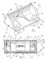
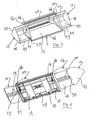
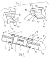
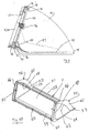
- the implement attachment of the present invention will be described with respect to a selectively expandable and retractable bucket/scraper which may be selectively attached and detached from an implement via conventional means. Further, the present invention will be described with respect to two embodiments. A first embodiment shown in Figures 1-12 (sometimes referred to as the Figure 1 embodiment) and a second embodiment shown in Figures 13-23 (sometimes referred to as the Figure 13 embodiment).
- the implement attachment 10 of the present invention includes a plurality of bucket members including a center bucket 11 and a pair of expandable side buckets or side bucket extensions 12 and 14.
- the bucket members 11, 12 and 14 are operatively connected relative to a main frame or frame assembly 15.
- the side bucket extensions 12 and 14 are operatively connected to be selectively movable relative to the frame assembly 15 and relative to the center bucket 11 between a fully retracted position as shown in Figures 1 and 2 and a fully expanded position as shown in Figures 3 and 4.
- the center bucket 11 is operatively connected to be laterally fixed relative to the frame assembly 15.
- the frame assembly 15 includes a pair of vertically spaced, laterally extending upper 16 and lower 18 frame members and a pair of laterally spaced, vertically extending loader or vehicle mounting plates 19 and 20 which are rigidly secured to the frame members 16 and 18.
- the frame members 16 and 18 are rigid tubular members.
- the implement mounting plates 19 and 20 are conventional "Quik-Tach" means which are connected with the rearward side of the frame members 16 and 18 by welding or the like. The plates 19 and 20 function to connect the implement attachment to a driven vehicle in a conventional manner.
- a double acting cylinder means comprised of the interconnected pair of hydraulic cylinders 22 and 23 are connected to the back surface of a filler plate 38 respectively by welding or brackets, or the like. With this mounting, the cylinders 22 and 23 extend laterally outwardly from opposite sides of the mounting plates 19,20. The laterally extending cylinders are located approximately midway between the frame members 16 and 18.
- the cylinders 22 and 23 include extendable cylinder rods 24 and 25 which are selectively extendable and retractable in opposite directions from the ends of the cylinders 22 and 23.
- the cylinders 22 and 23 are driven by a hydraulic power source from the implement (not shown) via the hydraulic hoses 26.
- the lower frame member 18 includes means in the form of three pairs of hinge mount brackets 28 for pivotally connecting the center bucket 11 to the frame assembly 15 as will be described in detail below.
- the hinge mount brackets 28 are rigidly connected to the rearward face of the lower frame member 18 by welding and each includes an opening 29 to receive a pivot pin.
- a slide track bracket 30 is rigidly connected to the upper surface of the upper frame member 16 by welding or the like.
- the bracket 30 includes a downwardly extending portion 31 which is spaced from the forward surface of the frame member 16 to define an upper bucket extension slide track 32.
- a similar slide track bracket 34 is rigidly secured by welding or the like to the lower surface of the lower frame member 18.
- This bracket 34 has an upwardly extending portion 35 which is spaced from the front surface of the lower frame member 18 to define a lower bucket extension slide track 36.
- Both of the slide track brackets 30 and 34 extend for the entire length of their respective upper and lower frame members 16 and 18.
- a pair of return spring attachment plates 27 are connected by welding or the like to the rear surface of the frame member 16. These plates 27 include an opening to receive one end of a return spring 33 ( Figures 2, 4, 6 and 12) to limit forward pivotal movement of the frame assembly 15 and the bucket extensions 12 and 14 relative to the center bucket 11 as will be described below.
- a main frame filler plate 38 is connected between the frame members 16 and 18 by welding or the like.
- the filler plate 38 is constructed of metal with a sufficient thickness to assist in providing rigidity to the frame assembly 15 and to sufficiently resist loading and/or scraping forces.
- the plate 38 is provided with a forwardly curved portion 39 to accommodate and protect the cylinder members 22 and 23.
- the plate 38 and the curved portion 39 extend laterally for a substantial portion of the length of the frame members 16 and 18.
- the filler plate 38 extends slightly beyond the inner edges of the bucket extensions 12 and 14 when in their expanded positions.
- the side bucket extensions 12 and 14 are designed for selective lateral movement relative to the frame assembly 15 and the center bucket 11 between a fully retracted position as shown in Figures 1 and 2 and a fully expanded position as shown in Figures 2, 4 and 8.
- Each of the bucket extensions 12 and 14 includes top and bottom bucket extension slide guide edges 48 and 49, a bucket extension outer side wall 41, a bucket extension inner side wall or reinforcing rib 47 and a bucket extension rear or back wall or plate 42.
- the bottom wall 40 includes an inner side edge 43 and a forward or leading edge 44 which is designed to engage the ground during a loading or scraping function. A rearward portion of the bottom 40 is rigidly connected to the back wall 42 by welding or the like.
- the rearward portion of the bottom wall 40 curves upwardly near its rearward edge as shown by reference character 45 in Figures 7 and 9.
- the back wall or plate 42 includes a lateral cylinder protecting channel 46 and the top and bottom slide guide edges 48 and 49.
- the top slide guide edge 48 is designed to slide laterally within the upper slide track 32, while the bottom slide guide edge 49 is designed to slide laterally within the lower slide track 36.
- the back wall 42 is wider in the lateral direction than the bottom wall 40 between the side wall 41 and the inner edge 43.
- This additional width (within the slide tracks 32 and 36) functions to support the bucket extensions 12 and 14 in their expanded position and to resist loading and scraping forces.
- the back wall 42 is at least about 20% wider, more preferably at least about 30% wider and most preferably about 33% wider than its corresponding bottom all 40.
- the bucket extension inner side wall which functions as a reinforcing rib 47 is welded to a portion of the back wall 42 and to a top surface portion of the bottom wall 40 near the inner edge 43.
- the rib 47 functions to reinforce and provide rigidity to the bucket extensions 12 and 14.
- Each of the side walls 41 is rigidly connected to the outer edge of the back wall 42 and to the outer edge of the bottom wall 40 by welding or the like.
- the outer peripheral edges of the side walls 41 extend a limited distance beyond the bottom surface of the bottom wall 40 and the rearward surface of the back wall 42 as shown. This enables the inner peripheral surface of the walls 41 to engage the outer surface of one of the side wall portions 55 and 56 of the center bucket 11 as described below.
- Each of the side walls 41 includes an opening near its rearward edge to receive a respective one of the outer ends of the cylinder rods 24 and 25 ( Figure 8).
- an outer threaded end of each of the cylinder rods 24 and 25 extends through a corresponding opening in one of the side walls 41 and is connected thereto by a threaded nut 50.
- the center bucket 11 is shown best in Figures 10 and 11, with reference also being made to Figures 1-4 showing relationship of the center bucket member 11 to the frame assembly 15 and the expandable side bucket members 12 and 14.
- the center bucket 11 includes a bottom wall 51, upper 52 and lower 54 rear wall frame members and a pair of side wall portions 55 and 56.
- the bottom wall 51 includes a front or leading edge 58, a pair of side edges and a rearward portion 59.
- the side edges comprise a main side edge portion 62 and a forward side edge portion 53.
- the rearward portion 59 extends upwardly and rearwardly from the main portion of the bottom wall 51.
- Each of the side wall portions 55 and 56 includes a rearward leg or portion 60, a bottom wall portion which is connected with and defines the bottom wall side edges 62 and a forwardly extending portion 61.
- the side wall portions 55 and 56 are integrally formed from a metal material having sufficient thickness to resist the various forces exerted on the center bucket during use.
- the rearward portion 60 is rigidly connected between the lower frame member 54 and the upper frame member 52 by welding, while the bottom wall portion is connected with and define the side edges 62 of the bottom wall 51 by welding.
- the forwardly extending portion 61 extends from the upper end of the portion 60 to the forward end of the portion 62.
- the side wall portions 60, 61 and 62 define an opening 64 in each of the side wall portions 55 and 56 to accommodate lateral movement of the side buckets 12 and 14 as will be described in greater detail below.
- the openings 64 are sufficiently large to permit passage of walls 40 and 42 of the bucket extensions 12 and 14 during expansion and retraction movement, but slightly smaller than the side walls 41.
- the forward side edge portions 53 are at both ends of the forward edge 58 of the bottom wall 51. These edge portions 53 extend laterally outwardly from the side edge portion 62. This lateral extension of the edge portions 53 insures that when the bucket extensions 12 and 14 are in their fully extended positions, there will be a complete clean sweep across the entire width of the expanded bucket
- a plurality of pin hinge members 65 are rigidly connected to the bottom frame member 54 by welding or the like and are laterally spaced so that they mate with the three pairs of hinge mount brackets 28 of the frame assembly 15.
- the center bucket 11 is connected with the frame assembly 15 for limited pivotal movement.
- Such pivotal movement is permitted by positioning the pin hinge members 65 between respective pairs of hinge mount brackets 28 and inserting a pivot pin through the respective openings in the pin hinges 65 and the brackets 28.
- a pair of vertically extending frame members 66 are rigidly connected to the outer edge of the side wall portion 60 and between the upper and lower frame members 52 and 54. These members 66 function to reinforce and provide rigidity to the rearward frame portion of the center bucket 11. As described in greater detail below, these members 66 also function to limit the rearward pivotal movement of the frame 15 and bucket extensions 12 and 14 relative to the center bucket 11.
- a pair of return spring attachment pins 37 are connected with a rear face of the frame members 66 by welding or the like. These pins 37 have a portion extending inwardly from the frame members 66 for connection to an end of the return springs 33 ( Figures 2, 4, 6 and 12).
- the pins 37 may include a spring retaining groove or opening if desired.
- the frame assembly 15 and each of the bucket extensions 12 and 14 are operatively connected with the implement via the mounting plates 19 and 20 and conventional attachment means.
- the frame assembly 15 and the bucket extensions 12 and 14 raise, lower and tilt in response to corresponding movement of the implement attachment means.
- the bucket extensions 12 and 14 are also movable laterally relative to the frame assembly 15 between a fully retracted and a fully expanded position.
- the center bucket 11 is connected with the main frame assembly 15 via the hinges 65 and the hinge mount brackets 28.
- each of the springs 33 is a tension spring with one end connected with a respective plate 27 on the frame member 16 and an opposite end connected with a respective pin 37 on the frame member 66. Then as the side bucket extensions 12 and 14 pivot forwardly relative to the center bucket 11, the springs 33 are tensioned to limit such pivotal movement.
- the attachment is connected with the implement in a conventional manner via a conventional connection between the driven implement and the mounting plates 19 and 20 ( Figures 2, 4, 5 and 6).
- the hydraulic hoses 26 for the cylinders 22 and 23 are also connected to a hydraulic power source on the driven implement.
- the implement attachment 10 of the present invention When attached to the driven implement, the implement attachment 10 of the present invention is ready for use.
- the bucket extensions 12 and 14 are fully retracted via the cylinders 22 and 23 so that the inner surfaces of the bucket extension side walls 41 engage the outer surfaces of the side wall portions 55 and 56.
- the bottom walls 40 of the bucket extensions 12 and 14 are supported on the upper surface of the center bucket bottom wall 51 and the center bucket 11 is movable in unison with the frame assembly 15 and the bucket extensions 12 and 14.
- the implement attachment 10 can be used as a conventional bucket loader to lift, carry and dump snow, dirt or other materials or can be used as a scraper with a width equal to the width of the center bucket member 11.
- the center bucket leading edge 58 functions as the sole scraping or cutting edge.
- the hydraulic cylinders 22 and 23 are actuated by the operator on the driven implement. This causes the bucket extensions 12 and 14 to move laterally outwardly relative to the frame assembly 15 and the center bucket 11.
- the inner edges 43 of the side bucket bottom walls 40 are positioned outside the outer side edge portions 62 of the center bucket bottom wall 51. This relative position of the side edges 43 and the side edge portions 62, together with the pivotal connection between the center bucket 11 and the frame assembly 15 enables the side buckets 12 and 14 (and the frame assembly 15) to pivot forwardly a limited distance relative to the center bucket 11 when the attachment is tipped.
- This limited forward pivotal movement of the bucket extensions 12 and 14 relative to the center bucket 11 is desirable, particularly when the attachment is used in a scraping function and the attachment is tipped or tilted forwardly.
- the leading edges 44 of the side bucket extensions 12 and 14 are at the same level relative to the ground or supporting surface 70 ( Figure 12) as the leading edge 58 of the center bucket 11.
- This relative pivotal movement is automatic and results from engagement of the leading edge 58 of the center bucket 11 with the ground 70 when the expanded bucket is tipped forwardly.
- the leading edges 44 and 58 of the bottom walls 40 and 51 will automatically adjust to ground level.
- the implement attachment When in its fully expanded position, the implement attachment functions as a loader or scraper with an expanded load capacity and width.
- the attachment is tilted back or raised so that the frame members 66 of the bucket 11 and the upper frame member 16 are in substantial engagement.
- the bottom walls 40 and 51 are substantially parallel to one another, with the bottom surface of the bottom wall 40 even with or slightly above the top surface of the bottom wall 51.
- the cylinders 22 and 23 are then actuated to retract the extensions 12 and 14 until they reach their fully retracted positions.
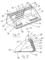
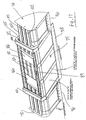
- FIG. 13-23 A further embodiment of the implement attachment of the present invention is shown in Figures 13-23. Similar to the embodiment of Figures 1-12, the embodiment of Figures 13-23 is an adjustable implement attachment which can be selectively adjusted to alter its load capacity and/or width. It includes a center bucket member 75, a pair of side bucket members or bucket extensions 76 and 78 and a main frame or frame assembly 79. The bucket extensions 76 and 78 are moveable outwardly and inwardly between a fully retracted position as shown in Figure 13 and a fully expanded position as shown in Figures 15 and 17.
- the movement of the bucket extensions 76 and 78 between its retracted and expanded positions is accomplished by a pair of hydraulic cylinders (not shown in Figures 13-22) similar to the cylinders 22 and 23 of the Figure 1 embodiment. These cylinders would be connected between the main frame 79 and the bucket extensions 76 and 78.
- the center bucket 75 of the Figure 13 embodiment is substantially the same as the center bucket 11 of the Figure 1 embodiment. Accordingly, the detailed description of the Figure 1 embodiment is incorporated into the disclosure of the Figure 13 embodiment.
- the main difference between the two embodiments relates to the means for guiding the lateral movement of the bucket extensions 76 and 78 relative to the center bucket 75 and the main frame 79 between their retracted and expanded positions. Accordingly, the main structural differences between the two embodiments involve the slide or guide rails 81 and 82 of the main frame 79 and the corresponding slide or guide rails 100, 101 and 102 of the bucket extensions 76 and 78.
- the main frame 79 includes a plurality of laterally extending slide or guide rails comprising a pair of outer slide rails 81 and a pair of inner slide rails 82.
- the inner slide rails 82 are tubular in construction with a generally trapezoid cross-sectional configuration.
- each of the inner slide rails 82 includes a pair of beveled exterior slide or guide surfaces 84.
- the pair of outer slide rails 81 are also tubular in construction and each includes an inner facing beveled exterior slide or guide surface 85 adjacent to one of the inner slide rails 82.
- the slide rails 81 and 82 are rigidly connected via welding or the like to a conventional implement attachment means such as the pair of "Quik-Tach" plates 86.
- a conventional implement attachment means such as the pair of "Quik-Tach" plates 86.
- Such Quik-Tach plates 86 provides a mounting arrangement for a skid steel vehicle.
- the slide rails 81 and 82 are further rigidly interconnected via welding near their ends via the pair of retainer tubes or frame members 88.
- a plurality of filler plates 83 are provided between adjacent rails 81,82 and between the plates 86 to provide a bucket back between the bucket extensions 76 and 78. These filler plates 83 are welded to the rear surface of the slide rails 81 and 82.
- the rails 81 and 82 are vertically spaced from one another to provide a sliding recess or gap 87 between adjacent rails 81,82. These gaps 87, defined by the surfaces 84 and 85 and the forward surfaces of the plates 86 and 83, provide sliding recesses for the bucket extensions 76 and 78.
- a plurality of hinge members 89 and pivot pins 90 are rigidly secured to the bottom slide rail 81 for pivotal connection to the center bucket 75 as shown and described with respect to the Figure 1 embodiment.
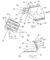
- each of the bucket extensions includes a bottom wall 91, a rear wall 92, an outer side wall 94, an inner side wall 95 and a front edge 96. These elements are substantially the same as corresponding elements of the Figure 1 embodiment.
- the back wall 92 and the bottom wall 91 are rigidly secured such as by welding or the like to a pair of skid bars 98.
- a tubular member 99 is formed from the top end of the rear wall 92 to provide stability and reinforcement to the bucket extensions 76 and 78.
- An end cap may be welded to the open inner end of the member 99.
- a plurality of slide or guide rails 100, 101 and 102 are rigidly secured to the rearward side of the skid bars 98 by welding or the like. As shown, these slide rails 100-102 extend from the outer side wall 94, along the rear wall 92 and for a limited distance past the inner side wall 95. The slide rails 100-102 extend laterally and are vertically spaced from one another to provide a sliding recess or gap 103 ( Figure 20) between adjacent rails 100-102. Each of the slide rails 100-102 is tubular in construction and has a generally trapezoid cross section with a pair of beveled surfaces 104 extending outwardly from the skid bars 98 as shown best in Figure 20. The inner ends of the slide rails 100-102 are provided with a beveled end 105.
- the slide rails 100-102 of each of the side buckets 76 and 78 are designed to slide laterally within the slide recesses 87 ( Figure 23) of the main frame 79. During this sliding relationship, the beveled surfaces 104 of the slide rails 100-102 engage the beveled surfaces 84 and 85 of the slide rails 82 and 83, respectively.
- a spring such as the spring 33 of the Figure 1 embodiment or other means can be provided between the frame 79 and a portion of the center bucket 75 to limit the permitted pivotal movement between the frame 79 and bucket 75.
- a retaining bar 108 ( Figure 15) can be welded to the front edges of the slide rails 100-102 to provide stability and reinforcement and to prevent the slide rails 100-102 and thus the bucket extensions 76 and 78 from pivotable movement relative to the retainer tubes 88 when the bucket extensions are in their expanded positions.
Landscapes
- Engineering & Computer Science (AREA)
- Mechanical Engineering (AREA)
- Mining & Mineral Resources (AREA)
- Civil Engineering (AREA)
- General Engineering & Computer Science (AREA)
- Structural Engineering (AREA)
- Shovels (AREA)
- Body Structure For Vehicles (AREA)
Applications Claiming Priority (1)
| Application Number | Priority Date | Filing Date | Title |
|---|---|---|---|
| US11/220,226 US7429158B2 (en) | 2004-09-07 | 2005-09-06 | Expandable implement attachment |
Publications (2)
| Publication Number | Publication Date |
|---|---|
| EP1760202A2 true EP1760202A2 (de) | 2007-03-07 |
| EP1760202A3 EP1760202A3 (de) | 2014-01-22 |
Family
ID=37526971
Family Applications (1)
| Application Number | Title | Priority Date | Filing Date |
|---|---|---|---|
| EP06004874.1A Withdrawn EP1760202A3 (de) | 2005-09-06 | 2006-03-09 | Verbreiterbare Schaufel |
Country Status (3)
| Country | Link |
|---|---|
| US (1) | US7429158B2 (de) |
| EP (1) | EP1760202A3 (de) |
| CA (1) | CA2538519C (de) |
Cited By (2)
| Publication number | Priority date | Publication date | Assignee | Title |
|---|---|---|---|---|
| CN105765131A (zh) * | 2013-10-17 | 2016-07-13 | 哈尼斯菲格技术公司 | 用于铲斗的衬垫系统 |
| CN113250259A (zh) * | 2021-06-30 | 2021-08-13 | 徐州立方机电设备制造有限公司 | 一种可扩容的挖掘机挖斗 |
Families Citing this family (32)
| Publication number | Priority date | Publication date | Assignee | Title |
|---|---|---|---|---|
| ITGE20030015A1 (it) * | 2003-02-25 | 2004-08-26 | Gianluca Malacrino | Benna o pala a capacita' regolabile |
| ITBO20070654A1 (it) * | 2007-09-25 | 2009-03-26 | Assaloni 1920 S R L | Lama sgombraneve estensibile |
| US20090293323A1 (en) * | 2008-05-29 | 2009-12-03 | Gordon Lyle Van Camp | Wheel loader front mounted ditch cleaning attachment |
| US8887413B2 (en) | 2012-02-13 | 2014-11-18 | Thomas Andrew Miller | Expanding material box for equipment |
| US20130298429A1 (en) * | 2012-05-09 | 2013-11-14 | Cal G. Niemela | Combination snow blower and plow |
| CN102979116A (zh) * | 2012-12-04 | 2013-03-20 | 上海尔轩工贸有限公司 | 挖斗 |
| US8967286B2 (en) | 2013-03-04 | 2015-03-03 | Kois Brothers Equipment Co., Inc. | Lateral mount for vehicle mounted implement |
| US8955238B1 (en) | 2013-03-06 | 2015-02-17 | John R. Castruccio | Adjustable plow blade |
| US9015970B1 (en) * | 2014-01-24 | 2015-04-28 | Northland Leasing Inc. | Convertible bucket having folding wings and winglets |
| US10005651B2 (en) * | 2015-03-06 | 2018-06-26 | Js Innovations Llc | Implements and methods of manufacturing and using same |
| ES2592523B1 (es) * | 2015-05-28 | 2017-10-31 | Francisco CARO MORALES | Equipo para excavación y limpieza de cunetas, zanjas o similares. |
| GB2541751A (en) * | 2015-08-31 | 2017-03-01 | Anthony Furlong Patrick | Hydraulic variable extending digger bucket |
| DK3565928T3 (da) | 2017-01-05 | 2021-09-06 | 9407 4895 Quebec Inc | Skrabeindretning til rydning af en vejbaneoverflade |
| WO2018213863A1 (en) | 2017-05-23 | 2018-11-29 | Austin Engineering Ltd | Bucket |
| US10544561B2 (en) * | 2017-12-04 | 2020-01-28 | C.A. Hull Co., Inc. | Collector assembly |
| US10113297B1 (en) * | 2018-02-13 | 2018-10-30 | R2 Manufacturing LLC | Back guard attachable to a bucket, method of forming the back guard, and bucket assembly including the back guard |
| US11078644B2 (en) * | 2018-04-11 | 2021-08-03 | Deere & Company | Hybrid load bucket assembly |
| CN108678047A (zh) * | 2018-05-30 | 2018-10-19 | 南京工业职业技术学院 | 一种双缸液压伸缩式挖掘机铲头 |
| CN108755809A (zh) * | 2018-07-26 | 2018-11-06 | 南京工业职业技术学院 | 一种双缸液压伸缩式挖掘机铲头 |
| US11525237B2 (en) * | 2018-08-31 | 2022-12-13 | Clark Equipment Company | Loader bucket |
| CN109468915A (zh) * | 2018-10-26 | 2019-03-15 | 中铁二院成都勘察设计研究院有限责任公司 | 一种路基填筑施工方法及其设备 |
| CA3080101C (en) | 2019-05-08 | 2025-12-16 | Cal G. Niemela | Wing plow apparatus for vehicle |
| USD909427S1 (en) * | 2019-07-03 | 2021-02-02 | Austin Engineering Limited | Excavator bucket |
| USD909428S1 (en) * | 2019-07-03 | 2021-02-02 | Austin Engineering Limited | Upper section of an excavator bucket |
| US11668068B2 (en) * | 2020-03-05 | 2023-06-06 | Caterpillar Underground Mining Pty. Ltd. | Bucket for underground loading machine |
| CN112049176B (zh) * | 2020-08-07 | 2024-06-11 | 徐州庚辰工贸有限公司 | 一种可开挖不同坡度的挖机斗可调节装置 |
| CA3129773A1 (en) | 2020-09-02 | 2022-03-02 | Cal G. Niemela | Articulating vehicle snow plow |
| CN112031060A (zh) * | 2020-09-10 | 2020-12-04 | 上海三一重机股份有限公司 | 可变斗容式铲斗和挖掘机 |
| WO2022120424A1 (en) * | 2020-12-08 | 2022-06-16 | Bradken Resources Pty Limited | Bucket |
| CA3166770A1 (en) * | 2021-07-09 | 2023-01-09 | Atelier D'usinage Jules Roberge Inc. | Extendable plow blade |
| GB2620555B (en) * | 2022-07-04 | 2024-07-17 | Jj Mac Ltd | Tip bucket assembly with adjustable bucket width |
| CN115162438B (zh) * | 2022-07-20 | 2023-08-01 | 江苏徐工国重实验室科技有限公司 | 一种伸缩式铲斗、控制系统及控制方法 |
Family Cites Families (6)
| Publication number | Priority date | Publication date | Assignee | Title |
|---|---|---|---|---|
| US3782573A (en) * | 1971-05-28 | 1974-01-01 | Nat Oats Co Inc | Bucket for use on a loader, tractor or the like |
| JPS52157603U (de) * | 1976-05-25 | 1977-11-30 | ||
| US4633601A (en) * | 1984-09-25 | 1987-01-06 | Esco Corporation | Excavating shovel |
| FR2656640B1 (fr) * | 1989-12-29 | 1992-07-17 | Suau Eric | Godet pour engins de terrassement de largeur reglable. |
| GB2341843A (en) * | 1998-09-24 | 2000-03-29 | John Edward Mansfield | Variable width excavation bucket |
| ITGE20030015A1 (it) * | 2003-02-25 | 2004-08-26 | Gianluca Malacrino | Benna o pala a capacita' regolabile |
-
2005
- 2005-09-06 US US11/220,226 patent/US7429158B2/en not_active Expired - Fee Related
-
2006
- 2006-03-02 CA CA2538519A patent/CA2538519C/en not_active Expired - Fee Related
- 2006-03-09 EP EP06004874.1A patent/EP1760202A3/de not_active Withdrawn
Cited By (4)
| Publication number | Priority date | Publication date | Assignee | Title |
|---|---|---|---|---|
| CN105765131A (zh) * | 2013-10-17 | 2016-07-13 | 哈尼斯菲格技术公司 | 用于铲斗的衬垫系统 |
| CN105765131B (zh) * | 2013-10-17 | 2018-02-23 | 哈尼斯菲格技术公司 | 用于铲斗的衬垫系统 |
| CN113250259A (zh) * | 2021-06-30 | 2021-08-13 | 徐州立方机电设备制造有限公司 | 一种可扩容的挖掘机挖斗 |
| CN113250259B (zh) * | 2021-06-30 | 2021-09-07 | 徐州立方机电设备制造有限公司 | 一种可扩容的挖掘机挖斗 |
Also Published As
| Publication number | Publication date |
|---|---|
| CA2538519C (en) | 2014-07-08 |
| US7429158B2 (en) | 2008-09-30 |
| CA2538519A1 (en) | 2007-03-06 |
| EP1760202A3 (de) | 2014-01-22 |
| US20060182590A1 (en) | 2006-08-17 |
Similar Documents
| Publication | Publication Date | Title |
|---|---|---|
| CA2538519C (en) | Expandable implement attachment | |
| US7360327B2 (en) | Material moving pusher/bucket | |
| US6314666B1 (en) | Material moving blade | |
| CA2346600C (en) | Improved folding pusher | |
| US4074448A (en) | Hinged snowplow, conversion kit, and method therefor | |
| EP0909855B1 (de) | Laderfahrzeug | |
| US5169278A (en) | Vertical lift loader boom | |
| US5775438A (en) | Earth working scraper apparatus | |
| US3529678A (en) | Mounting for bulldozer blades | |
| US4545721A (en) | Combined lift fork and bucket device for attachment to a vehicle | |
| DE10340671A1 (de) | Auslegeranordnung für schwenkbares Nutzfahrzeug | |
| US5156215A (en) | Counterweight assembly for crawler tractor | |
| US4854811A (en) | Bucket-blade attachment for tractors | |
| US12098513B2 (en) | Material handling bucket apparatus and method for handling application material with a loader | |
| EP0012236A1 (de) | Fahrzeug mit verstellbarem Belastungsgewicht | |
| EP1329357A2 (de) | Kipperfahrzeug | |
| EP1908883A1 (de) | Externe Endplattenverstärkung für Materialschubvorrichtung | |
| US7214026B2 (en) | Easy maintenance and/or service utility vehicle with extendable utility boom | |
| CN111684871A (zh) | 宽度可调的松土机组件 | |
| US5771980A (en) | Soil leveling apparatus with improved frame and hitch | |
| EP0474210A1 (de) | Vertikal hebender Laderausleger | |
| US8857080B1 (en) | Transfer bucket and ejector assembly for a front end loader vehicle | |
| US2304786A (en) | Scraper | |
| US20110052359A1 (en) | Tiltable bucket attachment | |
| US6367177B1 (en) | Trench restoration apparatus |
Legal Events
| Date | Code | Title | Description |
|---|---|---|---|
| PUAI | Public reference made under article 153(3) epc to a published international application that has entered the european phase |
Free format text: ORIGINAL CODE: 0009012 |
|
| AK | Designated contracting states |
Kind code of ref document: A2 Designated state(s): AT BE BG CH CY CZ DE DK EE ES FI FR GB GR HU IE IS IT LI LT LU LV MC NL PL PT RO SE SI SK TR |
|
| AX | Request for extension of the european patent |
Extension state: AL BA HR MK YU |
|
| RIC1 | Information provided on ipc code assigned before grant |
Ipc: E02F 3/40 20060101AFI20130830BHEP |
|
| PUAL | Search report despatched |
Free format text: ORIGINAL CODE: 0009013 |
|
| AK | Designated contracting states |
Kind code of ref document: A3 Designated state(s): AT BE BG CH CY CZ DE DK EE ES FI FR GB GR HU IE IS IT LI LT LU LV MC NL PL PT RO SE SI SK TR |
|
| AX | Request for extension of the european patent |
Extension state: AL BA HR MK YU |
|
| RIC1 | Information provided on ipc code assigned before grant |
Ipc: E02F 3/40 20060101AFI20131218BHEP |
|
| AKY | No designation fees paid | ||
| REG | Reference to a national code |
Ref country code: DE Ref legal event code: R108 |
|
| REG | Reference to a national code |
Ref country code: DE Ref legal event code: R108 Effective date: 20140924 |
|
| STAA | Information on the status of an ep patent application or granted ep patent |
Free format text: STATUS: THE APPLICATION IS DEEMED TO BE WITHDRAWN |
|
| 18D | Application deemed to be withdrawn |
Effective date: 20140723 |