EP1760213A2 - Rechtwinklige Fachwerkträgerbefestigung - Google Patents
Rechtwinklige Fachwerkträgerbefestigung Download PDFInfo
- Publication number
- EP1760213A2 EP1760213A2 EP06254541A EP06254541A EP1760213A2 EP 1760213 A2 EP1760213 A2 EP 1760213A2 EP 06254541 A EP06254541 A EP 06254541A EP 06254541 A EP06254541 A EP 06254541A EP 1760213 A2 EP1760213 A2 EP 1760213A2
- Authority
- EP
- European Patent Office
- Prior art keywords
- flange
- substantially planar
- planar portion
- connector
- structural member
- Prior art date
- Legal status (The legal status is an assumption and is not a legal conclusion. Google has not performed a legal analysis and makes no representation as to the accuracy of the status listed.)
- Granted
Links
- 229910052751 metal Inorganic materials 0.000 claims description 32
- 239000002184 metal Substances 0.000 claims description 32
- 230000003014 reinforcing effect Effects 0.000 claims description 15
- 238000005452 bending Methods 0.000 claims description 11
- 238000000034 method Methods 0.000 claims description 8
- 229910000831 Steel Inorganic materials 0.000 claims description 7
- 239000010959 steel Substances 0.000 claims description 7
- 238000005520 cutting process Methods 0.000 claims description 4
- 238000004080 punching Methods 0.000 claims 2
- 238000005304 joining Methods 0.000 abstract description 5
- 239000002023 wood Substances 0.000 description 4
- 238000000576 coating method Methods 0.000 description 3
- 238000005553 drilling Methods 0.000 description 3
- 238000009432 framing Methods 0.000 description 3
- HCHKCACWOHOZIP-UHFFFAOYSA-N Zinc Chemical compound [Zn] HCHKCACWOHOZIP-UHFFFAOYSA-N 0.000 description 2
- 239000011248 coating agent Substances 0.000 description 2
- 229910001220 stainless steel Inorganic materials 0.000 description 2
- 239000010935 stainless steel Substances 0.000 description 2
- 229910052725 zinc Inorganic materials 0.000 description 2
- 239000011701 zinc Substances 0.000 description 2
- OKTJSMMVPCPJKN-UHFFFAOYSA-N Carbon Chemical compound [C] OKTJSMMVPCPJKN-UHFFFAOYSA-N 0.000 description 1
- XECAHXYUAAWDEL-UHFFFAOYSA-N acrylonitrile butadiene styrene Chemical compound C=CC=C.C=CC#N.C=CC1=CC=CC=C1 XECAHXYUAAWDEL-UHFFFAOYSA-N 0.000 description 1
- 229920000122 acrylonitrile butadiene styrene Polymers 0.000 description 1
- 239000004676 acrylonitrile butadiene styrene Substances 0.000 description 1
- 239000000853 adhesive Substances 0.000 description 1
- 230000001070 adhesive effect Effects 0.000 description 1
- 229910052782 aluminium Inorganic materials 0.000 description 1
- XAGFODPZIPBFFR-UHFFFAOYSA-N aluminium Chemical compound [Al] XAGFODPZIPBFFR-UHFFFAOYSA-N 0.000 description 1
- -1 aluminum) Chemical class 0.000 description 1
- 229910052799 carbon Inorganic materials 0.000 description 1
- 239000002131 composite material Substances 0.000 description 1
- 239000000835 fiber Substances 0.000 description 1
- 238000004519 manufacturing process Methods 0.000 description 1
- 239000000463 material Substances 0.000 description 1
- 150000002739 metals Chemical class 0.000 description 1
- 239000004033 plastic Substances 0.000 description 1
- 229920003023 plastic Polymers 0.000 description 1
- 238000003466 welding Methods 0.000 description 1
Images


Classifications
-
- E—FIXED CONSTRUCTIONS
- E04—BUILDING
- E04B—GENERAL BUILDING CONSTRUCTIONS; WALLS, e.g. PARTITIONS; ROOFS; FLOORS; CEILINGS; INSULATION OR OTHER PROTECTION OF BUILDINGS
- E04B7/00—Roofs; Roof construction with regard to insulation
- E04B7/02—Roofs; Roof construction with regard to insulation with plane sloping surfaces, e.g. saddle roofs
- E04B7/06—Constructions of roof intersections or hipped ends
- E04B7/063—Hipped ends
-
- E—FIXED CONSTRUCTIONS
- E04—BUILDING
- E04B—GENERAL BUILDING CONSTRUCTIONS; WALLS, e.g. PARTITIONS; ROOFS; FLOORS; CEILINGS; INSULATION OR OTHER PROTECTION OF BUILDINGS
- E04B1/00—Constructions in general; Structures which are not restricted either to walls, e.g. partitions, or floors or ceilings or roofs
- E04B1/18—Structures comprising elongated load-supporting parts, e.g. columns, girders, skeletons
- E04B1/26—Structures comprising elongated load-supporting parts, e.g. columns, girders, skeletons the supporting parts consisting of wood
- E04B1/2604—Connections specially adapted therefor
- E04B1/2608—Connectors made from folded sheet metal
Definitions
- the connector of the present invention has particular application as a sheet metal hanger for use in a hip roof, joining supported jack trusses to supporting girder trusses.
- a hip roof has sloped ends as well as sloped sides. The roof rises by inclining planes from all four sides of the building of which it is a part. The line where an adjacent sloping side and sloping end meet is generally called the "hip.”
- the four hips generally run from a corner of the building to the peak of the roof at a 45 degree angle.
- the hips are not merely lines, but are either rafters or trusses.
- the ends of the roof can be built up from flat-topped trusses that step down from the roof peak.
- the ends of the roof can be made from sloping jack trusses that run parallel to the roof peak and which are supported by the end wall of the building and by a girder truss.
- the ends of the roof can also be made with a combination of stepped-down flat-topped trusses and jack trusses, in which case the flat-topped truss closest to the end wall is the girder truss supporting the jack trusses.
- any truss that does not span from wall to wall is referred to as a jack truss, so the truss on the hip line could be referred to as a jack truss.
- the truss on the hip line will be referred to as a hip truss in the present application.
- the jack trusses that run parallel to the roof peak and are supported by a girder truss, there generally are shorter jack trusses that are supported by the hip trusses where the hip trusses approach the corners of the roof and building.
- the framing members may be lumber or wood trusses, but in the most preferred form the framing members are hollow steel trusses.
- the connection is most typically made at the junction of the supporting girder truss and one hip truss framing member.
- the present invention provides a connector (1) comprising:
- the connector When the connector is formed from a sheet metal blank that is bent and formed into its final configuration, the embossments, along with the outlines of the flanges and fastener opening, are created while the blank is still flat, after which the flanges are bent out of the blank, creating the junctures between them.
- the connector of the present invention is specifically designed to join a jack truss to a supporting girder truss that has an open web.
- An advantage of the present invention is that it better joins members because it fastens to each of the supporting and supported members with fasteners that enter the members from at least two different principle angles or directions, so that the fasteners, attaching the connector to a member, are not all withdrawn in the same direction to disassemble the connection. This is especially helpful for hollow metal members.
- An advantage of the present invention is that it is economically formed from a substantially rectangular blank that wastes virtually no material in the manufacturing process.
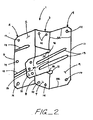
- FIG. 1 is a perspective view of the present invention used as a jack truss to girder truss connector.
- FIG. 2 is a perspective view of a right angle girder tie connector formed according to the present invention.
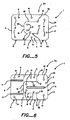
- FIG. 3 is a top plan view of a portion of the jack truss to girder truss connection, illustrating a first jack truss and a first girder truss, both wood members, connected by a connector formed according to the present invention.
- FIG. 4 is a top plan view of a portion of another jack truss to girder truss connection using a connector formed according to the present invention. The view is similar to that shown in FIG. 3 except that the connected members are hollow metal members.
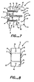
- FIG. 5 is a top plan view of a sheet metal blank without reinforcing embossments prior to bending from which a sheet metal connector formed according to the present invention is constructed.
- FIG. 6 is a top plan view of a sheet metal blank with reinforcing embossments prior to bending from which a sheet metal connector formed according to the present invention is constructed.
- FIG. 7 is an end elevation view of a sheet metal connector formed according to the present invention.
- FIG. 8 is a side elevation view of a sheet metal connector formed according to the present invention.
- FIG. 9 is a top plan view of a sheet metal blank without reinforcing embossments prior to bending from which an alternate preferred embodiment of a sheet metal connector formed according to the present invention is constructed.
- FIG. 10 is a top plan view of a sheet metal blank with reinforcing embossments prior to bending from which an alternate preferred embodiment of a sheet metal connector formed according to the present invention is constructed.
- FIG. 11 is an end elevation view of an alternate preferred embodiment of a sheet metal connector formed according to the present invention.
- FIG. 12 is a side elevation view of an alternate preferred embodiment of a sheet metal connector formed according to the present invention.
- FIG. 13 is a top plan view of a short truss supported by two girder trusses, using two connectors formed according to the present invention, in which the connected members are hollow metal members.
- FIG. 14 is a top plan view of a portion of the jack truss to girder truss connection showing the use of the preferred fasteners.
- the present invention is a connector 1 comprising a first flange 2, a second flange 3, angularly joined to the first flange 2, and a third flange 4, angularly joined to the second flange 3.
- first flange 2 and a portion of the third flange 4 attach to a supported structural member 17, and the second flange 3 and a portion of the third flange 4 attach to the supporting structural member 16.
- the first flange 2 has a first substantially planar portion 5 and a first edge 6.
- the second flange 3 has a first substantially planar portion 7.
- the second flange 3 is angularly joined to the first flange 2 at a first juncture 8 that is at least partially opposite the first edge 6 of the first flange 2 across the first flange 2.
- the third flange 4 has a first substantially planar portion 9 and a second substantially planar 10 portion integrally joined to the first substantially planar portion 9 in substantially the same plane as the first substantially planar portion 9. There is a first edge 11 on the first substantially planar portion 9, and a second edge 18 on the second substantially planar portion 10.
- the first substantially planar portion 9 of the third flange 4 is angularly joined to the second flange 3 at a second juncture 12 that is at least partially opposite the first edge 11 of the third flange 4 across the first substantially planar portion 9 of the third flange 4.
- the second juncture 12 is at least partially opposite the first juncture 8 across the second flange 3.
- the second substantially planar portion 10 of the third flange 4 extends past the second juncture 12.
- the second substantially planar portion 10 of the third flange 4 extends away from the first edge 11 of the third flange 4.
- At least part of the second edge 18 of the third flange 4 is oriented in the same direction as the first edge 6 of the first flange 2, and at least part of the second edge 18 of the third flange 4 is oriented in substantially the opposite direction from the first edge 11 of the third flange 4.
- the first flange 2 has at least one reinforcing embossment 13.
- the first flange 2 has two reinforcing embossments 13.
- the third flange 4 preferably has at least one reinforcing embossment 13.
- the third flange 4 has one embossment 13.
- the third flange 4 has two embossments 13.
- any reinforcing embossment 13 in the first flange 2 is elongated and oriented substantially perpendicular to the first juncture 8.
- the reinforcing embossments 13 in the third flange 4 are preferably elongated, oriented substantially perpendicular to the second juncture 12, and span from the first substantially planar portion 9 of the third flange 4 to the second substantially planar portion 10 of the third flange 4.
- the first flange 2, the second flange 3 and the third flange 4 each have a plurality of fastener openings 14.
- the second flange 3 is preferably orthogonal to the first flange 2 and to the third flange 4, and the first flange 2 and the third flange 4 occupy substantially parallel planes.
- the second flange 3 defines a plane that divides or transects the third flange splitting it into the second substantially planar portion 10 of the third flange 4 and the first substantially planar portion 9 of the third flange 4.
- the second substantially planar portion 10 of the third flange 4 extends from the second juncture 12, and past the plane of division created by the second flange 3 in one direction toward the edge 18, and the first substantially planar portion 9 of the third flange 4 extends past the plane of division created by the second flange 3 in the opposite direction from the second substantially planar portion 10 of the third flange 4 towards edge 11.
- the first flange 2 extends from the plane of division created by the second flange 3 in the same direction as the second substantially planar portion 10 of the third flange 4.
- the connector 1 of the present invention connects a supporting structural member 16 and a supported structural member 17.
- the supporting structural member 16 is preferably fastened to the second flange 3 and the first substantially planar portion 9 of the third flange 4.
- the supported structural member 17 is fastened to the first flange 2 and the second substantially planar portion 10 of the third flange 4.
- the connector 1 will function if reversed, but that is not the preferred orientation.
- the supporting structural member 16 is preferably a supporting truss 16, and the supported structural member 17 is preferably a supported truss 17.
- the supporting truss 16 has a top chord 19, a bottom chord 20, and at least one web member 21 extending between the top chord 19 and the bottom chord 20.
- the connector 1 preferably interfaces with the web member 21 of the supporting truss 16.
- the supported truss 17 has a top chord 22, a bottom chord 23 and an end member 24 extending between the top chord 22 and the bottom chord 23.
- the connector 1 preferably interfaces with the end member 24 of the supported truss 17.
- the supporting structural member 16 and the supported structural member 17 are made primarily of metal. More preferably, the supporting structural member 16 and the supported structural member 17 are made primarily of hollow steel.
- the connector 1 of the present invention is used to form a connection 15 between trusses of the NuconSteel NuTruss system.
- the supporting structural member 16 and the supported structural member 17 are preferably fastened to the connector 1 with separate fasteners 25.
- the separate fasteners 25 are screws 25.
- the connection 15 could be formed without separate fasteners 25, if the connector 1 were formed with integral mechanical fasteners 25, or if adhesives or welding were used to fasten the connector 1 to the structural members 17 and 16. If the connector 1 were used with wood members, the preferred fasteners 25 would be self-drilling wood screws of the kind exemplified by the Simpson Strong-Tie SDS screw.
- the preferred fastener 25 would be self-drilling metal screws, which install quickly and easily with an automatic driver, most preferably #10 self-drilling metal screws, a standard in the industry.
- connection 15 of the present invention is formed by driving a plurality of the screws 25 through the second flange 3 into the supporting structural member 16, driving a plurality of the screws 25 through the first substantially planar portion 9 of the third flange 4 into the supporting structural member 16, driving a plurality of the screws 25 through the first flange 2 into the supported structural member 17, and driving a plurality of the screws 25 through the second substantially planar portion 10 of the third flange 4 into the supported structural member 17.
- the web member 21 of the supporting structural member 16 is preferably part of a web 27 between the top chord 19 and the bottom chord 20 of the supporting structural member 16.
- the web member 21 has first and second substantially planar sides 26.
- the first side 26 of the web member 21 is preferably within the web 27 and the second side 26 of the web member 21 faces out of the web 27.
- the second flange 3 interfaces with the second side 26 of the web member 21.
- the first substantially planar portion 9 of the third flange 4 preferably interfaces with the first side 26 of the web member 21.
- the end member 24 of the supported structural member 17 is part of a web 28 between the top chord 22 and the bottom chord 23 of the supported structural member 17.
- the end member 24 preferably has first and second substantially planar sides 29.
- the first side 29 of the end member 24 faces out of the web 28 and the second side 29 of the end member 24 faces out of the web 28 in the opposite direction from the first side 29 of the end member 24.
- the first flange 2 preferably interfaces with the first side 29 of the end member 24.
- the second substantially planar portion 10 of the third flange 4 interfaces with the second side 29 of the end member 24.
- a plurality of the screws 25 is preferably driven through the second flange 3 into the second side 26 of the web member 21.
- a second plurality of the screws 25 is preferably driven through the first substantially planar portion 9 of the third flange 4 into the first side 26 of the web member 21.
- a third plurality of the screws 25 is preferably driven through the first flange 2 into the first side 29 of the end member 24, and a fourth plurality of the screws 25 is driven through the second substantially planar portion 10 of the third flange 4 into the second side 29 of the end member 24.
- the connector 1 of the present invention is preferably formed by cutting a generally rectangular blank 30 from sheet metal, cutting the second substantially planar portion 10 of the third flange 4 in the blank 30, bending the first flange 2 up ninety degrees from the blank 30, forming the first juncture 8, and by bending the second substantially planar portion 10 of the third flange 4 down ninety degrees from the blank 30, forming the second juncture 12.
- first and second relief holes 31 are preferably punched in the blank 30 because the second substantially planar portion 10 of the third flange 4 is preferably cut from the first relief hole 31 to the second relief hole 31.
- fastener openings 14 are preferably punched in the blank 30 before the blank 30 is bent.
- the connector 1 can also be cast from metals (e.g. , aluminum), plastics (e.g., acrylonitrile butadiene styrene), composites ( e.g., carbon fibre) or the like. If the connector 1 is cast, the first and second junctures 8 and 12 would be cast rather than created by bending, but would otherwise be equivalent to bends created by bending. Similarly, the outline, fastener openings 14 and embossments 13 could all be cast, rather than cut, punched and, for instance, embossed.
- the first substantially planar portion 9 of the third flange 4 has four sides 32.
- the second substantially planar portion 10 of the third flange 4 preferably has four sides 33 as well.
- one of the sides 33 of the second substantially planar portion 10 is integrally joined to one of the sides 32 of the first substantially planar portion 9.
- the side 33 of the second substantially planar portion 10 that is integrally joined to one of the sides 32 of the first substantially planar portion 9 is preferably shorter than the side 32 of the first substantially planar portion 9 to which it is joined.
- the side 33 of the second substantially planar portion 10 that is integrally joined to one of the sides 32 of the first substantially planar portion 9 has two ends 34.
- the connector 1 of the present invention is formed from a single piece of sheet metal, preferably steel.
- the steel preferably has a galvanized coating, preferably at least G90, which is a minimum of .90 ounce of zinc per square foot of surface area. Heavier galvanized coatings are also possible, including hot-dip galvanized, which is a minimum of 2.0 ounces of zinc per square foot of surface area. Heavier galvanized coating generally demand the use of hot-dip galvanized fasteners 23.
- the connector 5 can also be made from stainless steel, preferably type 316L, which requires the use of stainless steel fasteners 23.
- the embodiment of the connector 1 of the present invention having two embossments in the third flange 4 is formed from a single piece of sheet metal, preferably steel, with the following dimensions when used to connect to a hollow metal web 27 that has a second side 26 having a width dimension of approximately 1.65 inches.
- the distance between first edge 6 and first juncture 8 is 1.7813 inches.
- the distance between first juncture 8 and second juncture 12 is 1.6563 inches.
- the distance between second juncture 12 and first edge 11 of third flange 4 is 1.3750 inches.
- first substantially planar portion 9 of the third flange 4 the distance between ends 34 is 2 inches.
- side 32 to which the side 33 of the second substantially planar portion 10 is integrally joined extends beyond both of the ends 34 of the side 33 for 1 inch, thus the overall width of the connector 1 is 4 inches.
- the distance between first juncture 8 and second juncture 12, preferably varies with the dimension of the second side 26 of the web 27.
- the embodiment of the connector 1 of the present invention having one embossment in the third flange 4 is formed from a single piece of sheet metal, preferably steel, with the following dimensions when used to connect to a hollow metal web 27 that has a second side 26 having a width dimension of approximately 1.65 inches.
- the distance between first edge 6 and first juncture 8 is 1.7813 inches.
- the distance between first juncture 8 and second juncture 12 is 1.6563 inches.
- the distance between second juncture 12 and first edge 11 of third flange 4 is 1.3750 inches.
- the distance between ends 34 is 1.5 inches.
- side 32 to which the side 33 of the second substantially planar portion 10 is integrally joined extends beyond both of the ends 34 of the side 33 for 0.875 inches, thus the overall width of the connector 1 is 3.25 inches.
Landscapes
- Engineering & Computer Science (AREA)
- Architecture (AREA)
- Physics & Mathematics (AREA)
- Electromagnetism (AREA)
- Civil Engineering (AREA)
- Structural Engineering (AREA)
- Joining Of Building Structures In Genera (AREA)
- Rod-Shaped Construction Members (AREA)
Applications Claiming Priority (1)
| Application Number | Priority Date | Filing Date | Title |
|---|---|---|---|
| US11/217,957 US8484927B2 (en) | 2005-08-31 | 2005-08-31 | Right-angle girder tie |
Publications (3)
| Publication Number | Publication Date |
|---|---|
| EP1760213A2 true EP1760213A2 (de) | 2007-03-07 |
| EP1760213A3 EP1760213A3 (de) | 2009-01-14 |
| EP1760213B1 EP1760213B1 (de) | 2011-05-11 |
Family
ID=37420895
Family Applications (1)
| Application Number | Title | Priority Date | Filing Date |
|---|---|---|---|
| EP06254541A Active EP1760213B1 (de) | 2005-08-31 | 2006-08-31 | Rechtwinklige Fachwerkträgerbefestigung |
Country Status (3)
| Country | Link |
|---|---|
| US (1) | US8484927B2 (de) |
| EP (1) | EP1760213B1 (de) |
| AT (1) | ATE509168T1 (de) |
Cited By (2)
| Publication number | Priority date | Publication date | Assignee | Title |
|---|---|---|---|---|
| NL1037216C2 (nl) * | 2009-08-20 | 2011-02-22 | Sierd Kooij | Verbindingselement, plano's en werkwijzen voor het vervaardigen van een dergelijk verbindingelement. |
| US8484927B2 (en) | 2005-08-31 | 2013-07-16 | Simpson Strong-Tie Company, Inc | Right-angle girder tie |
Families Citing this family (16)
| Publication number | Priority date | Publication date | Assignee | Title |
|---|---|---|---|---|
| CA2836943A1 (en) * | 2011-05-27 | 2012-12-06 | Albert CHUBAK | Assembly joiner |
| US10247215B2 (en) * | 2011-05-27 | 2019-04-02 | Albert Chubak | Assembly joiner |
| US8720129B2 (en) * | 2012-02-08 | 2014-05-13 | Simpson Strong-Tie Company, Inc. | Component hoist clip |
| US8601746B1 (en) * | 2012-08-29 | 2013-12-10 | John Karaim | Roof bracket assembly |
| US9091056B2 (en) * | 2013-12-31 | 2015-07-28 | Simpson Strong-Tie Company, Inc. | Multipurpose concrete anchor clip |
| US9145673B1 (en) * | 2014-11-25 | 2015-09-29 | Hugh A. Dantzer | Deck clip and modular deck assembly |
| DE102015007267A1 (de) * | 2015-06-10 | 2016-12-15 | Gebr. Schmidt GbR (vertretungsber. Gesellschafter: Andreas Schmidt, 33649 Bielefeld | Verbindungselement für Wandbauelemente |
| US9476194B1 (en) * | 2015-09-03 | 2016-10-25 | Usg Interiors, Llc | Framing clips |
| US9885178B1 (en) | 2016-08-04 | 2018-02-06 | Southern Wall Systems, Inc. | Covering support system |
| US9920514B1 (en) * | 2016-09-09 | 2018-03-20 | Columbia Insurance Company | Valley truss tie |
| US10480177B2 (en) | 2016-11-18 | 2019-11-19 | Illinois Tool Works Inc. | Wall panel blocking bracket and method of using same |
| US10889978B2 (en) * | 2017-12-21 | 2021-01-12 | Studco Australia Pty Ltd. | Method of connecting and installing a building member |
| US20190191868A1 (en) * | 2017-12-21 | 2019-06-27 | William Bowser | Modular table with angled leg coupler |
| US12338619B2 (en) * | 2021-06-27 | 2025-06-24 | Paul Matthews Mosher | Mass timber hanger |
| USD1028698S1 (en) * | 2022-04-04 | 2024-05-28 | Keith Harless | Hurricane tie |
| US12509876B2 (en) * | 2023-09-22 | 2025-12-30 | Safe Box Steel Structures Inc. | Framing brackets and systems for shipping container interior |
Citations (2)
| Publication number | Priority date | Publication date | Assignee | Title |
|---|---|---|---|---|
| US4817359A (en) | 1988-02-01 | 1989-04-04 | Simpson Strong-Tie Company, Inc. | Multiple wood truss connection |
| US5253465A (en) | 1992-02-26 | 1993-10-19 | Simpson Strong-Tie Company, Inc. | Multiple framing member connection |
Family Cites Families (33)
| Publication number | Priority date | Publication date | Assignee | Title |
|---|---|---|---|---|
| US1423991A (en) * | 1921-07-16 | 1922-07-25 | George W Brooks | Screed holder |
| US1943036A (en) * | 1929-11-19 | 1934-01-09 | John J O'reilly | Concrete, masonry, and steel construction |
| US2191979A (en) * | 1937-12-28 | 1940-02-27 | Merwin Mfg Company | Sleeper anchor |
| US2831222A (en) * | 1955-06-15 | 1958-04-22 | Wood Conversion Co | Wallboard clip |
| US3187389A (en) * | 1961-02-08 | 1965-06-08 | Wood Conversion Co | Panel board clip |
| US4106257A (en) * | 1977-06-24 | 1978-08-15 | Simpson Manufacturing Co., Inc. | Composite truss bearing clip |
| US4417431A (en) * | 1980-06-23 | 1983-11-29 | Zip-Rib, Inc. | Clip for retaining sheet metal roofing or siding |
| US4421366A (en) * | 1980-07-28 | 1983-12-20 | Chester Niziol | Self-assembly furniture |
| US4995605A (en) * | 1987-06-29 | 1991-02-26 | Conlab Inc. | Panel fastener clip and method of panel assembly |
| US5027573A (en) * | 1989-05-01 | 1991-07-02 | Simpson Strong-Tie Company, Inc. | Deck clip system, method and connector connection |
| US5042217A (en) * | 1990-11-08 | 1991-08-27 | Simpson Strong-Tie Company, Inc. | Light wood truss connection |
| US5488810A (en) * | 1993-08-24 | 1996-02-06 | Southeastern Metals Mfg. Co., Inc. | Post cap |
| US5442887A (en) * | 1993-11-09 | 1995-08-22 | Welsh; Holden A. | Seat and anchor assembly for a roof truss and wooden joist |
| US5555694A (en) * | 1995-01-27 | 1996-09-17 | Simpson Strong-Tie Company, Inc. | Structural hanger |
| CA2144664C (en) * | 1995-03-15 | 2008-08-19 | Ieradi Joseph | Collapsible building truss |
| US5653079A (en) * | 1995-12-21 | 1997-08-05 | United Steel Products Company | Truss bracket |
| US5806265A (en) * | 1996-01-25 | 1998-09-15 | Sluiter; Scott E. | Metal truss joining gusset |
| US5966893A (en) * | 1997-07-23 | 1999-10-19 | Quillin; David G. | Clip for retaining adjacent panels in a planar relationship |
| US6763634B1 (en) * | 1997-12-31 | 2004-07-20 | Thomas C. Thompson | Retrofit hurricane-earthquake clip |
| US6088988A (en) * | 1998-10-27 | 2000-07-18 | Sahramaa; Kimmo J. | Chord with inwardly depending ends and ridge connection system |
| US6230467B1 (en) * | 1999-02-18 | 2001-05-15 | Simpson Strong-Tie Co., Inc. | Steel joist hanger |
| US6254306B1 (en) * | 1999-06-29 | 2001-07-03 | Troy D. Williams | Skewable connector for metal trusses |
| US6446409B1 (en) * | 1999-10-13 | 2002-09-10 | Full Circle Industries, Inc. | Structural bracket for securing spanning and supporting members |
| US6560943B1 (en) * | 1999-12-14 | 2003-05-13 | Simpson Strong-Tie Company, Inc. | Lateral truss anchor |
| US6993882B2 (en) * | 2000-12-03 | 2006-02-07 | Simpson Strong-Tie Company, Inc. | Truss spacer and brace |
| US6513298B2 (en) * | 2001-01-04 | 2003-02-04 | Aegis Metal Framing Llc | Web connector |
| US20020112439A1 (en) * | 2001-02-16 | 2002-08-22 | Rosas Ted A. | Framing fastener for connecting construction support members |
| US20020124483A1 (en) * | 2001-03-09 | 2002-09-12 | Rosas Ted A. | Framing fastener for connecting construction support members |
| US6840020B2 (en) * | 2001-10-30 | 2005-01-11 | Simpson Strong-Tie Company, Inc. | Valley truss clip |
| US6993880B2 (en) * | 2002-11-01 | 2006-02-07 | Keymark Enterprises, Llc | Apparatuses and methods for manufacture and placement of truss assemblies |
| US7104024B1 (en) * | 2003-10-20 | 2006-09-12 | The Steel Network, Inc. | Connector for connecting two building members together that permits relative movement between the building members |
| US7891144B2 (en) * | 2004-08-04 | 2011-02-22 | Simpson Strong-Tie Company, I{umlaut over (n)}c. | Adjustable heavy girder tiedown |
| US8484927B2 (en) | 2005-08-31 | 2013-07-16 | Simpson Strong-Tie Company, Inc | Right-angle girder tie |
-
2005
- 2005-08-31 US US11/217,957 patent/US8484927B2/en active Active
-
2006
- 2006-08-31 EP EP06254541A patent/EP1760213B1/de active Active
- 2006-08-31 AT AT06254541T patent/ATE509168T1/de not_active IP Right Cessation
Patent Citations (2)
| Publication number | Priority date | Publication date | Assignee | Title |
|---|---|---|---|---|
| US4817359A (en) | 1988-02-01 | 1989-04-04 | Simpson Strong-Tie Company, Inc. | Multiple wood truss connection |
| US5253465A (en) | 1992-02-26 | 1993-10-19 | Simpson Strong-Tie Company, Inc. | Multiple framing member connection |
Cited By (2)
| Publication number | Priority date | Publication date | Assignee | Title |
|---|---|---|---|---|
| US8484927B2 (en) | 2005-08-31 | 2013-07-16 | Simpson Strong-Tie Company, Inc | Right-angle girder tie |
| NL1037216C2 (nl) * | 2009-08-20 | 2011-02-22 | Sierd Kooij | Verbindingselement, plano's en werkwijzen voor het vervaardigen van een dergelijk verbindingelement. |
Also Published As
| Publication number | Publication date |
|---|---|
| US8484927B2 (en) | 2013-07-16 |
| US20070044421A1 (en) | 2007-03-01 |
| EP1760213A3 (de) | 2009-01-14 |
| HK1101783A1 (en) | 2007-10-26 |
| ATE509168T1 (de) | 2011-05-15 |
| EP1760213B1 (de) | 2011-05-11 |
Similar Documents
| Publication | Publication Date | Title |
|---|---|---|
| EP1760213B1 (de) | Rechtwinklige Fachwerkträgerbefestigung | |
| CA2719864C (en) | Four-way radial connector | |
| EP2527547B1 (de) | Sattelanhänger für eine Struktur | |
| US5341619A (en) | Truss girder hanger connection | |
| CA2652932C (en) | Wide back flange hanger | |
| AU2005295722B2 (en) | Top flange hanger with strengthening embossment | |
| EP0637656B1 (de) | Gitterträger | |
| US8387333B2 (en) | Structural support device with web brace | |
| US4817359A (en) | Multiple wood truss connection | |
| US20090090082A1 (en) | Joining structure of roof using thin light-gauge shaped steel | |
| US20150000224A1 (en) | Modular wall stud brace | |
| US6427416B1 (en) | Connector plate | |
| US7367168B2 (en) | Skewed girder tie | |
| AU2002215699B2 (en) | Metal roof truss | |
| HK1101783B (en) | Right-angle girder tie | |
| HK1101782A (en) | Skewed girder tie | |
| WO2015135054A1 (en) | Modular wall stud brace | |
| JP2004316114A (ja) | 複合梁材 | |
| JPH01137062A (ja) | スロープ床板 | |
| WO2003078751A1 (en) | A method and a means for interconnecting board-like members | |
| GB2500030A (en) | Bracing element for a joist or truss |
Legal Events
| Date | Code | Title | Description |
|---|---|---|---|
| PUAI | Public reference made under article 153(3) epc to a published international application that has entered the european phase |
Free format text: ORIGINAL CODE: 0009012 |
|
| AK | Designated contracting states |
Kind code of ref document: A2 Designated state(s): AT BE BG CH CY CZ DE DK EE ES FI FR GB GR HU IE IS IT LI LT LU LV MC NL PL PT RO SE SI SK TR |
|
| AX | Request for extension of the european patent |
Extension state: AL BA HR MK YU |
|
| REG | Reference to a national code |
Ref country code: HK Ref legal event code: DE Ref document number: 1101783 Country of ref document: HK |
|
| PUAL | Search report despatched |
Free format text: ORIGINAL CODE: 0009013 |
|
| AK | Designated contracting states |
Kind code of ref document: A3 Designated state(s): AT BE BG CH CY CZ DE DK EE ES FI FR GB GR HU IE IS IT LI LT LU LV MC NL PL PT RO SE SI SK TR |
|
| AX | Request for extension of the european patent |
Extension state: AL BA HR MK RS |
|
| RIC1 | Information provided on ipc code assigned before grant |
Ipc: E04B 7/06 20060101ALI20081210BHEP Ipc: E04B 1/26 20060101AFI20081210BHEP |
|
| 17P | Request for examination filed |
Effective date: 20090714 |
|
| AKX | Designation fees paid |
Designated state(s): AT BE BG CH CY CZ DE DK EE ES FI FR GB GR HU IE IS IT LI LT LU LV MC NL PL PT RO SE SI SK TR |
|
| 17Q | First examination report despatched |
Effective date: 20090915 |
|
| GRAP | Despatch of communication of intention to grant a patent |
Free format text: ORIGINAL CODE: EPIDOSNIGR1 |
|
| GRAS | Grant fee paid |
Free format text: ORIGINAL CODE: EPIDOSNIGR3 |
|
| RAP1 | Party data changed (applicant data changed or rights of an application transferred) |
Owner name: SIMPSON STRONG-TIE CO., INC. |
|
| GRAA | (expected) grant |
Free format text: ORIGINAL CODE: 0009210 |
|
| RIN1 | Information on inventor provided before grant (corrected) |
Inventor name: NGUYEN, HIENC/O SIMPSON STRONG-TIE CO.INC. |
|
| AK | Designated contracting states |
Kind code of ref document: B1 Designated state(s): AT BE BG CH CY CZ DE DK EE ES FI FR GB GR HU IE IS IT LI LT LU LV MC NL PL PT RO SE SI SK TR |
|
| REG | Reference to a national code |
Ref country code: GB Ref legal event code: FG4D |
|
| REG | Reference to a national code |
Ref country code: CH Ref legal event code: EP |
|
| REG | Reference to a national code |
Ref country code: IE Ref legal event code: FG4D |
|
| REG | Reference to a national code |
Ref country code: DE Ref legal event code: R096 Ref document number: 602006021836 Country of ref document: DE Effective date: 20110622 |
|
| REG | Reference to a national code |
Ref country code: NL Ref legal event code: VDEP Effective date: 20110511 |
|
| PG25 | Lapsed in a contracting state [announced via postgrant information from national office to epo] |
Ref country code: LT Free format text: LAPSE BECAUSE OF FAILURE TO SUBMIT A TRANSLATION OF THE DESCRIPTION OR TO PAY THE FEE WITHIN THE PRESCRIBED TIME-LIMIT Effective date: 20110511 Ref country code: PT Free format text: LAPSE BECAUSE OF FAILURE TO SUBMIT A TRANSLATION OF THE DESCRIPTION OR TO PAY THE FEE WITHIN THE PRESCRIBED TIME-LIMIT Effective date: 20110912 Ref country code: SE Free format text: LAPSE BECAUSE OF FAILURE TO SUBMIT A TRANSLATION OF THE DESCRIPTION OR TO PAY THE FEE WITHIN THE PRESCRIBED TIME-LIMIT Effective date: 20110511 |
|
| REG | Reference to a national code |
Ref country code: HK Ref legal event code: GR Ref document number: 1101783 Country of ref document: HK |
|
| PG25 | Lapsed in a contracting state [announced via postgrant information from national office to epo] |
Ref country code: GR Free format text: LAPSE BECAUSE OF FAILURE TO SUBMIT A TRANSLATION OF THE DESCRIPTION OR TO PAY THE FEE WITHIN THE PRESCRIBED TIME-LIMIT Effective date: 20110812 Ref country code: IS Free format text: LAPSE BECAUSE OF FAILURE TO SUBMIT A TRANSLATION OF THE DESCRIPTION OR TO PAY THE FEE WITHIN THE PRESCRIBED TIME-LIMIT Effective date: 20110911 Ref country code: LV Free format text: LAPSE BECAUSE OF FAILURE TO SUBMIT A TRANSLATION OF THE DESCRIPTION OR TO PAY THE FEE WITHIN THE PRESCRIBED TIME-LIMIT Effective date: 20110511 Ref country code: AT Free format text: LAPSE BECAUSE OF FAILURE TO SUBMIT A TRANSLATION OF THE DESCRIPTION OR TO PAY THE FEE WITHIN THE PRESCRIBED TIME-LIMIT Effective date: 20110511 Ref country code: FI Free format text: LAPSE BECAUSE OF FAILURE TO SUBMIT A TRANSLATION OF THE DESCRIPTION OR TO PAY THE FEE WITHIN THE PRESCRIBED TIME-LIMIT Effective date: 20110511 Ref country code: SI Free format text: LAPSE BECAUSE OF FAILURE TO SUBMIT A TRANSLATION OF THE DESCRIPTION OR TO PAY THE FEE WITHIN THE PRESCRIBED TIME-LIMIT Effective date: 20110511 Ref country code: ES Free format text: LAPSE BECAUSE OF FAILURE TO SUBMIT A TRANSLATION OF THE DESCRIPTION OR TO PAY THE FEE WITHIN THE PRESCRIBED TIME-LIMIT Effective date: 20110822 Ref country code: CY Free format text: LAPSE BECAUSE OF FAILURE TO SUBMIT A TRANSLATION OF THE DESCRIPTION OR TO PAY THE FEE WITHIN THE PRESCRIBED TIME-LIMIT Effective date: 20110511 Ref country code: BE Free format text: LAPSE BECAUSE OF FAILURE TO SUBMIT A TRANSLATION OF THE DESCRIPTION OR TO PAY THE FEE WITHIN THE PRESCRIBED TIME-LIMIT Effective date: 20110511 |
|
| PG25 | Lapsed in a contracting state [announced via postgrant information from national office to epo] |
Ref country code: NL Free format text: LAPSE BECAUSE OF FAILURE TO SUBMIT A TRANSLATION OF THE DESCRIPTION OR TO PAY THE FEE WITHIN THE PRESCRIBED TIME-LIMIT Effective date: 20110511 |
|
| PG25 | Lapsed in a contracting state [announced via postgrant information from national office to epo] |
Ref country code: CZ Free format text: LAPSE BECAUSE OF FAILURE TO SUBMIT A TRANSLATION OF THE DESCRIPTION OR TO PAY THE FEE WITHIN THE PRESCRIBED TIME-LIMIT Effective date: 20110511 Ref country code: EE Free format text: LAPSE BECAUSE OF FAILURE TO SUBMIT A TRANSLATION OF THE DESCRIPTION OR TO PAY THE FEE WITHIN THE PRESCRIBED TIME-LIMIT Effective date: 20110511 |
|
| PG25 | Lapsed in a contracting state [announced via postgrant information from national office to epo] |
Ref country code: RO Free format text: LAPSE BECAUSE OF FAILURE TO SUBMIT A TRANSLATION OF THE DESCRIPTION OR TO PAY THE FEE WITHIN THE PRESCRIBED TIME-LIMIT Effective date: 20110511 Ref country code: SK Free format text: LAPSE BECAUSE OF FAILURE TO SUBMIT A TRANSLATION OF THE DESCRIPTION OR TO PAY THE FEE WITHIN THE PRESCRIBED TIME-LIMIT Effective date: 20110511 Ref country code: PL Free format text: LAPSE BECAUSE OF FAILURE TO SUBMIT A TRANSLATION OF THE DESCRIPTION OR TO PAY THE FEE WITHIN THE PRESCRIBED TIME-LIMIT Effective date: 20110511 Ref country code: DK Free format text: LAPSE BECAUSE OF FAILURE TO SUBMIT A TRANSLATION OF THE DESCRIPTION OR TO PAY THE FEE WITHIN THE PRESCRIBED TIME-LIMIT Effective date: 20110511 |
|
| PLBE | No opposition filed within time limit |
Free format text: ORIGINAL CODE: 0009261 |
|
| STAA | Information on the status of an ep patent application or granted ep patent |
Free format text: STATUS: NO OPPOSITION FILED WITHIN TIME LIMIT |
|
| PG25 | Lapsed in a contracting state [announced via postgrant information from national office to epo] |
Ref country code: MC Free format text: LAPSE BECAUSE OF NON-PAYMENT OF DUE FEES Effective date: 20110831 |
|
| REG | Reference to a national code |
Ref country code: CH Ref legal event code: PL |
|
| 26N | No opposition filed |
Effective date: 20120214 |
|
| PG25 | Lapsed in a contracting state [announced via postgrant information from national office to epo] |
Ref country code: CH Free format text: LAPSE BECAUSE OF NON-PAYMENT OF DUE FEES Effective date: 20110831 Ref country code: LI Free format text: LAPSE BECAUSE OF NON-PAYMENT OF DUE FEES Effective date: 20110831 |
|
| REG | Reference to a national code |
Ref country code: FR Ref legal event code: ST Effective date: 20120430 |
|
| REG | Reference to a national code |
Ref country code: IE Ref legal event code: MM4A |
|
| PG25 | Lapsed in a contracting state [announced via postgrant information from national office to epo] |
Ref country code: IT Free format text: LAPSE BECAUSE OF FAILURE TO SUBMIT A TRANSLATION OF THE DESCRIPTION OR TO PAY THE FEE WITHIN THE PRESCRIBED TIME-LIMIT Effective date: 20110511 |
|
| REG | Reference to a national code |
Ref country code: DE Ref legal event code: R097 Ref document number: 602006021836 Country of ref document: DE Effective date: 20120214 |
|
| PG25 | Lapsed in a contracting state [announced via postgrant information from national office to epo] |
Ref country code: IE Free format text: LAPSE BECAUSE OF NON-PAYMENT OF DUE FEES Effective date: 20110831 |
|
| PG25 | Lapsed in a contracting state [announced via postgrant information from national office to epo] |
Ref country code: FR Free format text: LAPSE BECAUSE OF NON-PAYMENT OF DUE FEES Effective date: 20110831 |
|
| PG25 | Lapsed in a contracting state [announced via postgrant information from national office to epo] |
Ref country code: LU Free format text: LAPSE BECAUSE OF NON-PAYMENT OF DUE FEES Effective date: 20110831 |
|
| PG25 | Lapsed in a contracting state [announced via postgrant information from national office to epo] |
Ref country code: BG Free format text: LAPSE BECAUSE OF FAILURE TO SUBMIT A TRANSLATION OF THE DESCRIPTION OR TO PAY THE FEE WITHIN THE PRESCRIBED TIME-LIMIT Effective date: 20110811 |
|
| PG25 | Lapsed in a contracting state [announced via postgrant information from national office to epo] |
Ref country code: TR Free format text: LAPSE BECAUSE OF FAILURE TO SUBMIT A TRANSLATION OF THE DESCRIPTION OR TO PAY THE FEE WITHIN THE PRESCRIBED TIME-LIMIT Effective date: 20110511 |
|
| PG25 | Lapsed in a contracting state [announced via postgrant information from national office to epo] |
Ref country code: HU Free format text: LAPSE BECAUSE OF FAILURE TO SUBMIT A TRANSLATION OF THE DESCRIPTION OR TO PAY THE FEE WITHIN THE PRESCRIBED TIME-LIMIT Effective date: 20110511 |
|
| PGFP | Annual fee paid to national office [announced via postgrant information from national office to epo] |
Ref country code: DE Payment date: 20190819 Year of fee payment: 14 |
|
| REG | Reference to a national code |
Ref country code: DE Ref legal event code: R119 Ref document number: 602006021836 Country of ref document: DE |
|
| PG25 | Lapsed in a contracting state [announced via postgrant information from national office to epo] |
Ref country code: DE Free format text: LAPSE BECAUSE OF NON-PAYMENT OF DUE FEES Effective date: 20210302 |
|
| PGFP | Annual fee paid to national office [announced via postgrant information from national office to epo] |
Ref country code: GB Payment date: 20240823 Year of fee payment: 19 |