EP1760247B1 - Armoire à rideau coulissant - Google Patents
Armoire à rideau coulissant Download PDFInfo
- Publication number
- EP1760247B1 EP1760247B1 EP06300926.0A EP06300926A EP1760247B1 EP 1760247 B1 EP1760247 B1 EP 1760247B1 EP 06300926 A EP06300926 A EP 06300926A EP 1760247 B1 EP1760247 B1 EP 1760247B1
- Authority
- EP
- European Patent Office
- Prior art keywords
- slider
- slat
- cabinet
- sliding
- rail
- Prior art date
- Legal status (The legal status is an assumption and is not a legal conclusion. Google has not performed a legal analysis and makes no representation as to the accuracy of the status listed.)
- Active
Links
Images
Classifications
-
- E—FIXED CONSTRUCTIONS
- E06—DOORS, WINDOWS, SHUTTERS, OR ROLLER BLINDS IN GENERAL; LADDERS
- E06B—FIXED OR MOVABLE CLOSURES FOR OPENINGS IN BUILDINGS, VEHICLES, FENCES OR LIKE ENCLOSURES IN GENERAL, e.g. DOORS, WINDOWS, BLINDS, GATES
- E06B9/00—Screening or protective devices for wall or similar openings, with or without operating or securing mechanisms; Closures of similar construction
- E06B9/02—Shutters, movable grilles, or other safety closing devices, e.g. against burglary
- E06B9/08—Roll-type closures
- E06B9/11—Roller shutters
- E06B9/115—Roller shutters specially adapted for furniture
-
- E—FIXED CONSTRUCTIONS
- E06—DOORS, WINDOWS, SHUTTERS, OR ROLLER BLINDS IN GENERAL; LADDERS
- E06B—FIXED OR MOVABLE CLOSURES FOR OPENINGS IN BUILDINGS, VEHICLES, FENCES OR LIKE ENCLOSURES IN GENERAL, e.g. DOORS, WINDOWS, BLINDS, GATES
- E06B9/00—Screening or protective devices for wall or similar openings, with or without operating or securing mechanisms; Closures of similar construction
- E06B9/02—Shutters, movable grilles, or other safety closing devices, e.g. against burglary
- E06B9/08—Roll-type closures
- E06B9/11—Roller shutters
- E06B9/15—Roller shutters with closing members formed of slats or the like
-
- E—FIXED CONSTRUCTIONS
- E06—DOORS, WINDOWS, SHUTTERS, OR ROLLER BLINDS IN GENERAL; LADDERS
- E06B—FIXED OR MOVABLE CLOSURES FOR OPENINGS IN BUILDINGS, VEHICLES, FENCES OR LIKE ENCLOSURES IN GENERAL, e.g. DOORS, WINDOWS, BLINDS, GATES
- E06B9/00—Screening or protective devices for wall or similar openings, with or without operating or securing mechanisms; Closures of similar construction
- E06B9/56—Operating, guiding or securing devices or arrangements for roll-type closures; Spring drums; Tape drums; Counterweighting arrangements therefor
- E06B9/58—Guiding devices
- E06B9/582—Means to increase gliss, light, sound or thermal insulation
Definitions
- the present invention relates to a curtain cabinet (x) comprising at least one vertical sliding curtain formed with a vertical end plate defining a movable edge of the curtain.
- This type of cabinet generally comprises two identical curtains by mirror symmetry. The two curtains are slidably movable away from each other to open the cabinet and move closer to each other to close the cabinet.
- the curtains are conventionally formed from vertical longitudinal blades which are hinged to each other.
- the vertical terminal blade is the last blade of the curtain and therefore forms the movable edge which defines the access opening to the interior of the cabinet.
- the curtain is provided with a handle which is conventionally arranged at the terminal blades.
- the present invention therefore relates more particularly to the field of curtain storage cabinets (x), very frequently used as office furniture.
- each blade of the curtain comprises an upper end and a lower end engaged in these sliding rails. It is the same for the end plate whose upper and lower ends are generally provided with sliding pads engaged in the sliding rails. Due to the gravity, the sliding shoe located at the lower end of the end plate comes into sliding contact with the bottom of the lower rail.
- the terminal blades are made of metal or plastic.
- the sliding pads are generally made of molded plastic.
- the sliding pads are mounted and fixed at both ends of the terminal blade.
- the fixing of the sliding pads can be carried out by any means, such as by engagement with force, latching, or screwing.
- the sliding rails are generally made of metal or plastic. The sliding pads thus ensure a good sliding of the terminal blade inside the rails.
- the sliding pads are generally made of plastic material, and they must be fixed to the ends of the end plate, it happens that the pads are damaged, which affects the proper functioning of the cabinet. It must be known that this type of curtain cabinet is often used with little care because of its purely functional use. Thus, the sliding pads are subjected to harsh conditions that can cause them to break. On the other hand, since the pads are separate pieces that must be manufactured separately by injection molding, they have a relatively significant cost. In addition, it is necessary to proceed to a mounting operation of the pads on the ends of the terminal blade, which takes time and generates a cost of assembly.
- the object of the present invention is to overcome the aforementioned drawbacks of the prior art by defining a vertical slip-sliding end plate whose robustness is improved and whose implementation is facilitated, and this at a lower cost.
- the present invention provides a curtain cabinet according to claim 1.
- the pad extends substantially perpendicularly to the vertical longitudinal direction of the blade and thus forms a kind of right angle bracket.
- the pad is obtained by folding.
- Metal, and more particularly sheet metal metal, is a particularly advantageous material for the realization of the end plate with integrated sliding shoe.
- the pad connects to the blade at a substantially straight edge, the edge being provided with at least one reinforcing rib to stabilize the orientation of the pad relative to the blade.
- the gadroon is made integrally with the pad.
- the gadroon may have a rounded profile.
- the gadroon is obtained by local deformation of the pad. This is particularly the case when the terminal blade is made of metal, and more particularly from sheet metal.
- the bottom of the rail has a convex profile whose surface is advantageously grained.
- the rounded gadroon (s) come into contact with the convex profile of the bottom of the rail, which considerably reduces the contact surface between the pad and the rail.
- the grainy surface further reduces the contact area between the pad and the bottom of the rail.
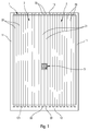
- the curtain cabinet shown on the figure 1 comprises vertical side walls 11, a base 12, and a cap 13.
- the fixed structure of the cabinet is further complemented by a rear face (not shown).
- These elements of the cabinet can be made of metal, for example sheet metal.
- the front face of the cabinet is formed by two curtains 2 which are arranged substantially vertically. These curtains 2 are made from vertical blades 20 which are fixed to each other in an articulated manner. Thus, the curtains 2 are flexible so that they can be wound along the side walls 11, inside the cabinet.
- the fixed structure of the cabinet is internally provided with vertical cheeks that extend substantially parallel to the side walls 11. The curtains 2, when moved to the open position, are housed between the cheeks and the side walls 11. The curtains 2 then wind themselves on a sliding rail with a hairpin path.
- the blades 21 are intended to come into contact with each other on their height in the closed position, as shown in FIG. figure 1 .
- the terminal blades 21 define a part of the opening edge giving access to the interior of the cabinet.
- These sliding rails extend to the level of the side walls 11 to allow the two curtains to be housed inside the cabinet, between the aforementioned internal cheeks and the walls 11.
- the lower and upper free ends of the blades 20 and 21 are engaged inside these lower rails and respective superiors.
- the lower ends 22 of the two end plates 21 are engaged in the lower rail 122 housed in the base 12, while the two upper free ends 23 of the two end plates 21 are engaged in the upper rail housed in the cap 13.
- the lower ends of the blades 20 engaged in the lower rail 122 are seen. Due to gravity, the lower ends of the blades come into contact with the bottom 123 of the rail 122.
- the rail 122 is fixed on a bottom plate 121 which is part of the bedrock 12.
- the end plates 21, which are made of metal, are provided at one or each of their free ends 22 and / or 23 of one or two sliding pads 25 engaged inside. from its respective lower and upper rail.
- the lower ends 22 of the end plates 21 are preferably provided with sliding pads, while the ends upper 23 may be devoid of sliding pads.
- the sliding pads at both ends of the blades are preferred.
- the sliding pads 25 are made integrally by the end plates 21. In other words, it is an integral part of the blade 21 which forms the sliding pad 25.
- each blade terminal 21 is provided with two integrally integrated sliding pads, so that the blade with its pads forms only one single piece.
- the end plates 21 are made by machining sheet metal plates, for example iron, steel or aluminum.
- Each flange is then machined, for example by deformation of material, so as to form, for example, two sliding flutes 251.
- a punching or punching technique can be used to obtain these sliding fluting 251.
- the two opposite flanges extend in the same plane as the core 210.
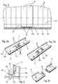
- a subsequent step consists of folding these flanges, so as to form the sliding pads 25. The folding of the flanges takes place at an angle substantially right, so the skids 25 then extend perpendicularly to the core 210, and more generally perpendicularly to the longitudinal direction of the end plates 21.
- the metal section can be cut so as to obtain two separate end plates, as can be seen on the figure 3c .
- the gadroons 251 of the pads 25 form a profile rounded outwards.
- the general shape of the gadroons is substantially similar to that of a grain of rice.
- the edge of the pad 25 is also rounded, so as to eliminate any sharp angle.
- Each pad can be provided with a single godron forming a rounded dome.
- the shoe 25 is arranged as shown on the figure 4 .
- the bottom 123 of the rail 122 is made with a convex profile which comes into contact with the godrons 251.
- the contact of the pad 25 with the bottom 123 of the rail is extremely reduced, which increases the sliding qualities of the rail. curtain inside the rails.
- the shoe 25 extends from the lower end of the blade 21 towards the inside of the cabinet, that is to say away from the base 12.
- the rail 122 is attached to the bottom plate 121 by means of a detent head 124 engaged in a suitable opening in the plate 121.
Landscapes
- Engineering & Computer Science (AREA)
- Structural Engineering (AREA)
- Architecture (AREA)
- Civil Engineering (AREA)
- Curtains And Furnishings For Windows Or Doors (AREA)
- Assembled Shelves (AREA)
Description
- La présente invention concerne une armoire à rideau(x) comprenant au moins un rideau vertical coulissant formé avec une lame terminale verticale définissant un bord mobile du rideau. Ce genre d'armoire comprend en général deux rideaux identiques par symétrie miroir. Les deux rideaux sont déplaçables en coulissement en éloignement l'un de l'autre pour ouvrir l'armoire et en rapprochement l'un de l'autre pour fermer l'armoire. Les rideaux sont conventionnellement formés à partir de lames longitudinales verticales qui sont articulées les unes par rapport aux autres. La lame terminale verticale constitue la dernière lame du rideau et forme par conséquent le bord mobile qui définit l'ouverture d'accès à l'intérieur de l'armoire. En général, le rideau est pourvu d'une poignée qui est conventionnellement disposée au niveau des lames terminales. La présente invention concerne par conséquent plus particulièrement le domaine des armoires de rangement à rideau(x), très fréquemment utilisées comme mobilier de bureau.
- Les rideaux de ce type d'armoire comprennent un bord supérieur et un bord inférieur engagés dans des rails de glissement fixés à la structure de l'armoire. Par conséquent, chaque lame du rideau comprend une extrémité supérieure et une extrémité inférieure engagées dans ces rails de glissement. Il en est de même pour la lame terminale dont les extrémités supérieure et inférieure sont généralement pourvues de patins de glissement engagés dans les rails de glissement. Du fait de la gravité, le patin de glissement situé à l'extrémité inférieure de la lame terminale vient en contact de glissement avec le fond du rail inférieur.
- En général, les lames terminales sont réalisées en métal ou en matière plastique. Les patins de glissement sont généralement réalisés en matière plastique moulée. Ainsi, les patins de glissement sont montés et fixés au niveau des deux extrémités de la lame terminale. La fixation des patins de glissement peut être réalisée par tout moyen, comme par engagement en force, encliquetage, ou vissage. D'autre part, les rails de glissement sont en général réalisés en métal ou en matière plastique. Les patins de glissement assurent ainsi un bon coulissement de la lame terminale à l'intérieur des rails.
- Cependant, du fait que les patins de glissement sont généralement réalisés en matière plastique, et qu'ils doivent être fixés aux extrémités de la lame terminale, il arrive que les patins soient endommagés, ce qui nuit au bon fonctionnement de l'armoire. Il faut en effet savoir que ce type d'armoires à rideau est souvent utilisé avec peu de ménagement du fait de son usage purement fonctionnel. Ainsi, les patins de glissement sont soumis à de rudes conditions qui peuvent engendrer leur rupture. D'autre part, étant donné que les patins sont des pièces séparées qui doivent être fabriquées séparément par injection moulage, ils présentent un prix de revient relativement significatif. De surcroît, il faut procéder à une opération de montage des patins sur les extrémités de la lame terminale, ce qui prend du temps et engendre un coût de montage.
- Dans l'art antérieur, on connaît le document
FR 2 836 350 DE 20 2004 004871 U1 décrit un rideau métallique qui coulisse dans des rails de guidage métalliques. - La présente invention a pour but de remédier aux inconvénients précités de l'art antérieur en définissant une lame terminale verticale à patin de glissement dont la robustesse est améliorée et dont la mise en oeuvre est facilitée, et ceci à moindre coût.
- Pour atteindre ces buts, la présente invention propose une armoire à rideau selon la revendication 1.
- Selon une caractéristique intéressante de l'invention, le patin s'étend sensiblement perpendiculairement à la direction longitudinale verticale de la lame et forme ainsi une sorte de cornière à angle droit. Avantageusement, le patin est obtenu par pliage. Le métal, et plus particulièrement la tôle métallique, est un matériau particulièrement avantageux pour la réalisation de la lame terminale à patin de glissement intégré.
- Selon un autre aspect de l'invention, le patin se connecte à la lame au niveau d'une arête sensiblement droite, l'arête étant pourvue d'au moins une nervure de renforcement pour stabiliser l'orientation du patin par rapport à la lame.
- Avantageusement, le godron est réalisé de manière monobloc avec le patin. Selon un autre aspect, le godron peut présenter un profil arrondi. Avantageusement, le godron est obtenu par déformation locale du patin. Ceci est notamment le cas lorsque la lame terminale est réalisée en métal, et plus particulièrement à partir de tôle métallique.
- Selon une autre caractéristique de l'invention permettant d'améliorer le glissement du rideau, le fond du rail présente un profil convexe dont la surface est avantageusement grenée. Ainsi, le ou les godrons arrondi(s) viennent en contact du profil convexe du fond du rail, ce qui réduit considérablement la surface de contact entre le patin et le rail. En outre, la surface grenée permet encore de réduire la surface de contact entre le patin et le fond du rail. Ainsi, le glissement du rideau dans les rails est considérablement amélioré.
- L'invention sera maintenant plus amplement décrite en référence aux dessins joints, donnant à titre d'exemple non limitatif un mode de réalisation de l'invention.
- Sur les figures :
- La
figure 1 est une vue de face d'une armoire à rideau conventionnelle incorporant l'invention, - La
figure 2 est une vue très largement agrandie d'un détail de lafigure 1 , - Les
figures 3a, 3b et 3c sont des vues en perspective d'une partie de lame terminale selon l'invention au cours de trois étapes successives de fabrication, et - La
figure 4 est une vue en coupe transversale verticale à travers la partie inférieure d'une lame terminale selon l'invention engagée dans un rail inférieur. - L'armoire à rideaux illustrée sur la
figure 1 comprend des parois latérales verticales 11, un soubassement 12, ainsi qu'un chapeau 13. La structure fixe de l'armoire est en outre complétée par une face arrière (non représentée). Ces éléments de l'armoire peuvent être réalisés en métal, par exemple de la tôle métallique. La face avant de l'armoire est formée par deux rideaux 2 qui sont disposés sensiblement verticalement. Ces rideaux 2 sont réalisés à partir de lames verticales 20 qui sont fixées les unes aux autres de manière articulée. Ainsi, les rideaux 2 sont flexibles de sorte qu'ils peuvent s'enrouler le long des parois latérales 11, à l'intérieur de l'armoire. Avantageusement, la structure fixe de l'armoire est pourvue intérieurement de joues verticales qui s'étendent sensiblement parallèlement aux parois latérales 11. Les rideaux 2, lorsqu'on les déplace vers la position ouverte, viennent se loger entre les joues et les parois latérales 11. Les rideaux 2 s'enroulent alors sur eux-mêmes dans un rail de glissement présentant un chemin en épingle à cheveux. Les rideaux 2, outre leur lame articulée 20, comprennent également chacun une lame terminale verticale 21 qui constitue le bord du rideau. Les lames 21 sont destinées à venir en contact l'une de l'autre sur leur hauteur en position fermée, comme représenté sur lafigure 1 . Lorsque le rideau est ouvert, les lames terminales 21 définissent une partie du bord d'ouverture donnant accès à l'intérieur de l'armoire. - Pour permettre le coulissement des rideaux 2, il est ainsi prévu un rail inférieur situé au niveau du soubassement 12 et un rail supérieur situé au niveau du chapeau 13. Ces rails de coulissement s'étendent jusqu'au niveau des parois latérales 11 pour permettre aux deux rideaux de se loger à l'intérieur de l'armoire, entre les joues internes susmentionnées et les parois 11. Pour permettre ce coulissement, les extrémités libres inférieures et supérieures des lames 20 et 21 sont engagées à l'intérieur de ces rails inférieurs et supérieurs respectifs. Ainsi, les extrémités inférieures 22 des deux lames terminales 21 sont engagées dans le rail inférieur 122 logées dans le soubassement 12, alors que les deux extrémités libres supérieures 23 des deux lames terminales 21 sont engagées dans le rail supérieur logé dans le chapeau 13. En se référant à la
figure 2 , on voit les extrémités inférieures des lames 20 engagées dans le rail inférieur 122. Du fait de la gravité, les extrémités inférieures des lames viennent en contact avec le fond 123 du rail 122. Le rail 122 est fixé sur une plaque de fond 121 qui fait partie du soubassement 12. - Selon l'invention, les lames terminales 21, qui sont réalisées en métal, sont pourvues au niveau d'une ou de chacune de leurs extrémités libres 22 et/ou 23 d'un ou de deux patins de glissement 25 engagés à l'intérieur de son rail respectif inférieur et supérieur. Les extrémités inférieures 22 des lames terminales 21 sont de préférence pourvues de patins de glissement, alors que les extrémités supérieures 23 peuvent être dépourvues de patins de glissement. Toutefois, les patins de glissement aux deux extrémités des lames sont préférés. Selon l'invention, les patins de glissement 25 sont réalisés de manière monobloc par les lames terminales 21. En d'autres termes, c'est une partie intégrante de la lame 21 qui forme le patin de glissement 25. De préférence, chaque lame terminale 21 est pourvue de deux patins de glissement intégrés monobloc, de sorte que la lame avec ses patins ne forme qu'une seule pièce unique. De préférence, les lames terminales 21 sont réalisées par usinage de plaques de tôle métalliques, par exemple du fer, de l'acier ou de l'aluminium.
- On se réfèrera maintenant aux
figures 3a, 3b et 3c pour expliquer de quelle manière on peut réaliser les patins de glissement des lames terminales 21 à partir d'une plaque de tôle métallique. Deux ou plusieurs lames terminales 21 peuvent être réalisées à partir d'un seul profilé métallique, comme on peut le voir sur lesfigures 3a et 3b . Le profilé métallique a été plié de manière appropriée afin de réaliser une âme centrale 210 qui va constituer la face frontale de la lame. D'autre part, cette âme 210 est bordée de part et d'autre par deux bords 211 et 212. Un des bords va servir à la fixation à une lame 20, alors que l'autre bord va constituer la tranche visible de la lame terminale destinée à venir en contact avec la tranche de l'autre lame terminale 21. Pour commencer, on découpe dans le profilé une fente F en forme de H. Deux brides symétriques par symétrie miroir se font ainsi face. Chaque bride est ensuite usinée, par exemple par déformation de matière, de manière à former par exemple deux godrons de glissement 251. On peut par exemple utiliser une technique de matriçage ou de poinçonnage pour obtenir ces godrons de glissement 251. Pour l'instant, les deux brides qui se font face s'étendent dans le même plan que l'âme 210. Une étape ultérieure consiste à replier ces brides, de manière à former les patins de glissement 25. Le pliage des brides s'effectue avec un angle sensiblement droit, de sorte que les patins 25 s'étendent alors perpendiculairement à l'âme 210, et plus généralement perpendiculairement à la direction longitudinale des lames terminales 21. Pour stabiliser l'orientation perpendiculaire des patins 25, on peut avantageusement former une ou plusieurs nervures de renforcement 252 au niveau de l'arête sensiblement rectiligne 253 qui relie le patin 25 à l'âme 210. Une fois les patins 25 ainsi obtenus, on peut couper le profilé métallique de manière à obtenir deux lames terminales distinctes, comme on peut le voir sur lafigure 3c . Les godrons 251 des patins 25 forment un profil arrondi vers l'extérieur. La forme générale des godrons est sensiblement similaire à celle d'un grain de riz. On peut également remarquer que le bord du patin 25 est également arrondi, de manière à éliminer tout angle vif. Chaque patin peut être pourvu d'un seul godron formant un dôme arrondi. - Une fois inséré dans le rail 122, le patin 25 est disposé comme représenté sur la
figure 4 . Avantageusement, le fond 123 du rail 122 est réalisé avec un profil convexe qui vient en contact avec le ou les godrons 251. Ainsi, le contact du patin 25 avec le fond 123 du rail est extrêmement réduit, ce qui augmente les qualités de glissement du rideau à l'intérieur des rails. On peut même prévoir de réaliser le profil convexe du fond du rail 123 avec une qualité de surface grenée, afin de réduire encore davantage le contact entre le rail et le patin. En se référant à lafigure 4 , on peut voir que le patin 25 s'étend à partir de l'extrémité inférieure de la lame 21 vers l'intérieur de l'armoire, c'est-à-dire en éloignement du soubassement 12. On peut également noter que le rail 122 est fixé à la plaque de fond 121 à l'aide d'une tête d'encliquetage 124 engagée dans une ouverture appropriée ménagée dans la plaque 121. - Grâce à l'invention, on obtient des lames terminales très faciles à réaliser, d'un coût de revient faible et incorporant en outre des patins de glissement particulièrement robustes.
Claims (8)
- Armoire à rideau comprenant au moins un rideau vertical coulissant (2) formé avec une lame terminale verticale (21) définissant un bord mobile du rideau, la lame étant adaptée à venir en contact d'une lame terminale (21) d'un autre rideau ou d'un montant de chambranle en position fermée de l'armoire, la lame terminale comprenant une extrémité inférieure (22) et une extrémité supérieure (23) engagées dans des rails de guidage respectifs (122), la lame comprenant au moins un patin de glissement (25) à une de ses extrémités, le patin venant en contact de glissement dans le rail respectif, le patin de glissement (25) et la lame (21) étant réalisés en métal de manière monobloc,
caractérisé en ce que le patin (25) comprend au moins un godron de glissement (251) destiné à venir en contact de glissement avec le fond (123) du rail (122). - Armoire selon la revendication 1, dans laquelle le patin (25) s'étend sensiblement perpendiculairement à la direction longitudinale verticale de la lame (21).
- Armoire selon la revendication 2, dans laquelle le patin (25) est obtenu par pliage.
- Armoire selon la revendication 2 ou 3, dans laquelle le patin (25) se connecte à la lame (21) au niveau d'une arête sensiblement droite (253), l'arête étant pourvue d'au moins une nervure de renforcement (252) pour stabiliser l'orientation du patin par rapport à la lame.
- Armoire selon l'une quelconque des revendications précédentes, dans laquelle le godron (251) est réalisé de manière monobloc avec le patin (25).
- Armoire selon l'une quelconque des revendications précédentes, dans laquelle le godron (251) présente un profil arrondi.
- Armoire selon l'une quelconque des revendications précédentes, dans laquelle le godron (251) est obtenu par déformation locale du patin.
- Armoire selon l'une quelconque des revendications précédentes, dans laquelle le fond (123) du rail (122) présente un profil convexe dont la surface est avantageusement grenée.
Applications Claiming Priority (1)
| Application Number | Priority Date | Filing Date | Title |
|---|---|---|---|
| FR0552678A FR2890298B1 (fr) | 2005-09-05 | 2005-09-05 | Armoire a rideau coulissant |
Publications (2)
| Publication Number | Publication Date |
|---|---|
| EP1760247A1 EP1760247A1 (fr) | 2007-03-07 |
| EP1760247B1 true EP1760247B1 (fr) | 2016-11-09 |
Family
ID=36572028
Family Applications (1)
| Application Number | Title | Priority Date | Filing Date |
|---|---|---|---|
| EP06300926.0A Active EP1760247B1 (fr) | 2005-09-05 | 2006-09-05 | Armoire à rideau coulissant |
Country Status (4)
| Country | Link |
|---|---|
| EP (1) | EP1760247B1 (fr) |
| ES (1) | ES2614750T3 (fr) |
| FR (1) | FR2890298B1 (fr) |
| PT (1) | PT1760247T (fr) |
Family Cites Families (4)
| Publication number | Priority date | Publication date | Assignee | Title |
|---|---|---|---|---|
| FR2070505A5 (fr) * | 1969-12-08 | 1971-09-10 | Picot Maurice | |
| GB1336773A (en) * | 1971-12-30 | 1973-11-07 | Sakow T | Table with roll-top cover |
| FR2836350B1 (fr) * | 2002-02-26 | 2004-06-25 | Atal Sa | Armoire a rideau coulissant |
| DE202004004874U1 (de) * | 2004-03-25 | 2004-06-03 | Roma Rolladensysteme Gmbh | Rolladen für Gebäudeöffnungen |
-
2005
- 2005-09-05 FR FR0552678A patent/FR2890298B1/fr not_active Expired - Lifetime
-
2006
- 2006-09-05 PT PT63009260T patent/PT1760247T/pt unknown
- 2006-09-05 ES ES06300926.0T patent/ES2614750T3/es active Active
- 2006-09-05 EP EP06300926.0A patent/EP1760247B1/fr active Active
Non-Patent Citations (1)
| Title |
|---|
| None * |
Also Published As
| Publication number | Publication date |
|---|---|
| EP1760247A1 (fr) | 2007-03-07 |
| FR2890298B1 (fr) | 2010-10-29 |
| PT1760247T (pt) | 2017-02-15 |
| FR2890298A1 (fr) | 2007-03-09 |
| ES2614750T3 (es) | 2017-06-01 |
Similar Documents
| Publication | Publication Date | Title |
|---|---|---|
| EP1127394B1 (fr) | Dispositif de fixation d'un fil sur un element porteur muni d'au moins une ouverture et ensemble porteur pour chemin de cables comportant au moins un tel dispositif | |
| FR2793453A1 (fr) | Glissiere pour siege de vehicule | |
| FR2665422A1 (fr) | Montant reglable de support de corbeilles a courrier. | |
| CH702149B1 (fr) | Corbeille pliable en fil métallique. | |
| EP1760247A1 (fr) | Armoire à rideau coulissant | |
| EP0943777B1 (fr) | Porte sectionnelle pré-montée pré-réglée, et son conditionnement | |
| EP1418293A1 (fr) | Systéme pour réaliser une cloison de retenue de liquide, telle une cloison de piscine, à partir de panneaux préfabriqués | |
| EP1870343B1 (fr) | Conteneur modulable et empilable | |
| FR2918101A1 (fr) | Verrou de securite automatique pour volet roulant, et volet roulant equipe d'un tel verrou. | |
| EP0558390A1 (fr) | Lame profilée pour fermeture à rideau, et rideau de fermeture correspondant | |
| EP2120651B1 (fr) | Boîte aux lettres, livrable en kit | |
| EP1396603B1 (fr) | Vantail pour porte sectionnelle et porte comprenant un tel vantail | |
| FR2723270A1 (fr) | Element de couvercle pour chemin de cables | |
| EP1798829B1 (fr) | Dalle de support de cables | |
| EP2461996B1 (fr) | Lecheur de vitre pour porte de vehicule et porte equipee d'un tel lecheur de vitre. | |
| FR2969939A3 (fr) | Outil de coupe pour sectionner des profiles | |
| FR2788636A1 (fr) | Adaptateur pour support de mecanisme, et support de mecanisme equipe d'au moins un tel adaptateur, notamment pour appareillage electrique | |
| FR3120757A1 (fr) | Pièce de fixation pour fixer un panneau sur un profilé, et ensemble de fixation comprenant une telle pièce et un profilé | |
| FR2691190A1 (fr) | Elément de ventilation incorporable dans la paroi extérieure d'une construction. | |
| EP1722065A1 (fr) | Panneau à poutres creuses de rigidification | |
| EP4448313A1 (fr) | Ouvrant pour véhicule comprenant un moyen d'étanchéité | |
| FR2970285A1 (fr) | Vantail de porte a panneau d'habillage interchangeable | |
| FR2873399A1 (fr) | Dispositif de trappe de visite pour caisson de tablier de volet roulant | |
| FR2717110A1 (fr) | Outil de poinçonnage pour profilé métallique. | |
| FR2798268A1 (fr) | Meuble metallique |
Legal Events
| Date | Code | Title | Description |
|---|---|---|---|
| PUAI | Public reference made under article 153(3) epc to a published international application that has entered the european phase |
Free format text: ORIGINAL CODE: 0009012 |
|
| AK | Designated contracting states |
Kind code of ref document: A1 Designated state(s): AT BE BG CH CY CZ DE DK EE ES FI FR GB GR HU IE IS IT LI LT LU LV MC NL PL PT RO SE SI SK TR |
|
| AX | Request for extension of the european patent |
Extension state: AL BA HR MK YU |
|
| 17P | Request for examination filed |
Effective date: 20070904 |
|
| AKX | Designation fees paid |
Designated state(s): AT BE BG CH CY CZ DE DK EE ES FI FR GB GR HU IE IS IT LI LT LU LV MC NL PL PT RO SE SI SK TR |
|
| 17Q | First examination report despatched |
Effective date: 20071025 |
|
| GRAP | Despatch of communication of intention to grant a patent |
Free format text: ORIGINAL CODE: EPIDOSNIGR1 |
|
| INTG | Intention to grant announced |
Effective date: 20160602 |
|
| GRAS | Grant fee paid |
Free format text: ORIGINAL CODE: EPIDOSNIGR3 |
|
| GRAA | (expected) grant |
Free format text: ORIGINAL CODE: 0009210 |
|
| AK | Designated contracting states |
Kind code of ref document: B1 Designated state(s): AT BE BG CH CY CZ DE DK EE ES FI FR GB GR HU IE IS IT LI LT LU LV MC NL PL PT RO SE SI SK TR |
|
| REG | Reference to a national code |
Ref country code: GB Ref legal event code: FG4D Free format text: NOT ENGLISH |
|
| REG | Reference to a national code |
Ref country code: AT Ref legal event code: REF Ref document number: 844098 Country of ref document: AT Kind code of ref document: T Effective date: 20161115 Ref country code: CH Ref legal event code: EP |
|
| REG | Reference to a national code |
Ref country code: IE Ref legal event code: FG4D Free format text: LANGUAGE OF EP DOCUMENT: FRENCH |
|
| REG | Reference to a national code |
Ref country code: DE Ref legal event code: R096 Ref document number: 602006050838 Country of ref document: DE |
|
| REG | Reference to a national code |
Ref country code: CH Ref legal event code: NV Representative=s name: BOVARD AG PATENT- UND MARKENANWAELTE, CH Ref country code: PT Ref legal event code: SC4A Ref document number: 1760247 Country of ref document: PT Date of ref document: 20170215 Kind code of ref document: T Free format text: AVAILABILITY OF NATIONAL TRANSLATION Effective date: 20170208 |
|
| REG | Reference to a national code |
Ref country code: NL Ref legal event code: FP |
|
| PG25 | Lapsed in a contracting state [announced via postgrant information from national office to epo] |
Ref country code: LV Free format text: LAPSE BECAUSE OF FAILURE TO SUBMIT A TRANSLATION OF THE DESCRIPTION OR TO PAY THE FEE WITHIN THE PRESCRIBED TIME-LIMIT Effective date: 20161109 |
|
| REG | Reference to a national code |
Ref country code: LT Ref legal event code: MG4D |
|
| PG25 | Lapsed in a contracting state [announced via postgrant information from national office to epo] |
Ref country code: LT Free format text: LAPSE BECAUSE OF FAILURE TO SUBMIT A TRANSLATION OF THE DESCRIPTION OR TO PAY THE FEE WITHIN THE PRESCRIBED TIME-LIMIT Effective date: 20161109 Ref country code: GR Free format text: LAPSE BECAUSE OF FAILURE TO SUBMIT A TRANSLATION OF THE DESCRIPTION OR TO PAY THE FEE WITHIN THE PRESCRIBED TIME-LIMIT Effective date: 20170210 Ref country code: SE Free format text: LAPSE BECAUSE OF FAILURE TO SUBMIT A TRANSLATION OF THE DESCRIPTION OR TO PAY THE FEE WITHIN THE PRESCRIBED TIME-LIMIT Effective date: 20161109 |
|
| PG25 | Lapsed in a contracting state [announced via postgrant information from national office to epo] |
Ref country code: FI Free format text: LAPSE BECAUSE OF FAILURE TO SUBMIT A TRANSLATION OF THE DESCRIPTION OR TO PAY THE FEE WITHIN THE PRESCRIBED TIME-LIMIT Effective date: 20161109 Ref country code: PL Free format text: LAPSE BECAUSE OF FAILURE TO SUBMIT A TRANSLATION OF THE DESCRIPTION OR TO PAY THE FEE WITHIN THE PRESCRIBED TIME-LIMIT Effective date: 20161109 Ref country code: IS Free format text: LAPSE BECAUSE OF FAILURE TO SUBMIT A TRANSLATION OF THE DESCRIPTION OR TO PAY THE FEE WITHIN THE PRESCRIBED TIME-LIMIT Effective date: 20170309 |
|
| REG | Reference to a national code |
Ref country code: ES Ref legal event code: FG2A Ref document number: 2614750 Country of ref document: ES Kind code of ref document: T3 Effective date: 20170601 |
|
| PG25 | Lapsed in a contracting state [announced via postgrant information from national office to epo] |
Ref country code: RO Free format text: LAPSE BECAUSE OF FAILURE TO SUBMIT A TRANSLATION OF THE DESCRIPTION OR TO PAY THE FEE WITHIN THE PRESCRIBED TIME-LIMIT Effective date: 20161109 Ref country code: EE Free format text: LAPSE BECAUSE OF FAILURE TO SUBMIT A TRANSLATION OF THE DESCRIPTION OR TO PAY THE FEE WITHIN THE PRESCRIBED TIME-LIMIT Effective date: 20161109 Ref country code: DK Free format text: LAPSE BECAUSE OF FAILURE TO SUBMIT A TRANSLATION OF THE DESCRIPTION OR TO PAY THE FEE WITHIN THE PRESCRIBED TIME-LIMIT Effective date: 20161109 Ref country code: CZ Free format text: LAPSE BECAUSE OF FAILURE TO SUBMIT A TRANSLATION OF THE DESCRIPTION OR TO PAY THE FEE WITHIN THE PRESCRIBED TIME-LIMIT Effective date: 20161109 Ref country code: SK Free format text: LAPSE BECAUSE OF FAILURE TO SUBMIT A TRANSLATION OF THE DESCRIPTION OR TO PAY THE FEE WITHIN THE PRESCRIBED TIME-LIMIT Effective date: 20161109 |
|
| REG | Reference to a national code |
Ref country code: DE Ref legal event code: R097 Ref document number: 602006050838 Country of ref document: DE |
|
| PG25 | Lapsed in a contracting state [announced via postgrant information from national office to epo] |
Ref country code: BG Free format text: LAPSE BECAUSE OF FAILURE TO SUBMIT A TRANSLATION OF THE DESCRIPTION OR TO PAY THE FEE WITHIN THE PRESCRIBED TIME-LIMIT Effective date: 20170209 |
|
| PLBE | No opposition filed within time limit |
Free format text: ORIGINAL CODE: 0009261 |
|
| STAA | Information on the status of an ep patent application or granted ep patent |
Free format text: STATUS: NO OPPOSITION FILED WITHIN TIME LIMIT |
|
| REG | Reference to a national code |
Ref country code: FR Ref legal event code: PLFP Year of fee payment: 12 |
|
| 26N | No opposition filed |
Effective date: 20170810 |
|
| PG25 | Lapsed in a contracting state [announced via postgrant information from national office to epo] |
Ref country code: SI Free format text: LAPSE BECAUSE OF FAILURE TO SUBMIT A TRANSLATION OF THE DESCRIPTION OR TO PAY THE FEE WITHIN THE PRESCRIBED TIME-LIMIT Effective date: 20161109 |
|
| REG | Reference to a national code |
Ref country code: CH Ref legal event code: PL |
|
| REG | Reference to a national code |
Ref country code: NL Ref legal event code: MM Effective date: 20171001 |
|
| PG25 | Lapsed in a contracting state [announced via postgrant information from national office to epo] |
Ref country code: MC Free format text: LAPSE BECAUSE OF FAILURE TO SUBMIT A TRANSLATION OF THE DESCRIPTION OR TO PAY THE FEE WITHIN THE PRESCRIBED TIME-LIMIT Effective date: 20161109 |
|
| REG | Reference to a national code |
Ref country code: IE Ref legal event code: MM4A |
|
| PG25 | Lapsed in a contracting state [announced via postgrant information from national office to epo] |
Ref country code: LU Free format text: LAPSE BECAUSE OF NON-PAYMENT OF DUE FEES Effective date: 20170905 Ref country code: NL Free format text: LAPSE BECAUSE OF NON-PAYMENT OF DUE FEES Effective date: 20171001 |
|
| PG25 | Lapsed in a contracting state [announced via postgrant information from national office to epo] |
Ref country code: LI Free format text: LAPSE BECAUSE OF NON-PAYMENT OF DUE FEES Effective date: 20170930 Ref country code: IE Free format text: LAPSE BECAUSE OF NON-PAYMENT OF DUE FEES Effective date: 20170905 Ref country code: CH Free format text: LAPSE BECAUSE OF NON-PAYMENT OF DUE FEES Effective date: 20170930 |
|
| PG25 | Lapsed in a contracting state [announced via postgrant information from national office to epo] |
Ref country code: IT Free format text: LAPSE BECAUSE OF NON-PAYMENT OF DUE FEES Effective date: 20170905 |
|
| REG | Reference to a national code |
Ref country code: FR Ref legal event code: PLFP Year of fee payment: 13 |
|
| REG | Reference to a national code |
Ref country code: ES Ref legal event code: FD2A Effective date: 20181025 |
|
| REG | Reference to a national code |
Ref country code: AT Ref legal event code: MM01 Ref document number: 844098 Country of ref document: AT Kind code of ref document: T Effective date: 20170905 |
|
| PG25 | Lapsed in a contracting state [announced via postgrant information from national office to epo] |
Ref country code: AT Free format text: LAPSE BECAUSE OF NON-PAYMENT OF DUE FEES Effective date: 20170905 |
|
| PG25 | Lapsed in a contracting state [announced via postgrant information from national office to epo] |
Ref country code: ES Free format text: LAPSE BECAUSE OF NON-PAYMENT OF DUE FEES Effective date: 20170906 |
|
| PG25 | Lapsed in a contracting state [announced via postgrant information from national office to epo] |
Ref country code: HU Free format text: LAPSE BECAUSE OF FAILURE TO SUBMIT A TRANSLATION OF THE DESCRIPTION OR TO PAY THE FEE WITHIN THE PRESCRIBED TIME-LIMIT; INVALID AB INITIO Effective date: 20060905 |
|
| REG | Reference to a national code |
Ref country code: AT Ref legal event code: UEP Ref document number: 844098 Country of ref document: AT Kind code of ref document: T Effective date: 20161109 |
|
| PG25 | Lapsed in a contracting state [announced via postgrant information from national office to epo] |
Ref country code: CY Free format text: LAPSE BECAUSE OF NON-PAYMENT OF DUE FEES Effective date: 20161109 |
|
| PG25 | Lapsed in a contracting state [announced via postgrant information from national office to epo] |
Ref country code: TR Free format text: LAPSE BECAUSE OF FAILURE TO SUBMIT A TRANSLATION OF THE DESCRIPTION OR TO PAY THE FEE WITHIN THE PRESCRIBED TIME-LIMIT Effective date: 20161109 |
|
| PGFP | Annual fee paid to national office [announced via postgrant information from national office to epo] |
Ref country code: BE Payment date: 20210930 Year of fee payment: 16 |
|
| PGFP | Annual fee paid to national office [announced via postgrant information from national office to epo] |
Ref country code: PT Payment date: 20210906 Year of fee payment: 16 |
|
| PGFP | Annual fee paid to national office [announced via postgrant information from national office to epo] |
Ref country code: DE Payment date: 20211008 Year of fee payment: 16 Ref country code: GB Payment date: 20211020 Year of fee payment: 16 |
|
| REG | Reference to a national code |
Ref country code: DE Ref legal event code: R119 Ref document number: 602006050838 Country of ref document: DE |
|
| PG25 | Lapsed in a contracting state [announced via postgrant information from national office to epo] |
Ref country code: PT Free format text: LAPSE BECAUSE OF NON-PAYMENT OF DUE FEES Effective date: 20230306 |
|
| GBPC | Gb: european patent ceased through non-payment of renewal fee |
Effective date: 20220905 |
|
| REG | Reference to a national code |
Ref country code: BE Ref legal event code: MM Effective date: 20220930 |
|
| PG25 | Lapsed in a contracting state [announced via postgrant information from national office to epo] |
Ref country code: DE Free format text: LAPSE BECAUSE OF NON-PAYMENT OF DUE FEES Effective date: 20230401 |
|
| PG25 | Lapsed in a contracting state [announced via postgrant information from national office to epo] |
Ref country code: BE Free format text: LAPSE BECAUSE OF NON-PAYMENT OF DUE FEES Effective date: 20220930 |
|
| PG25 | Lapsed in a contracting state [announced via postgrant information from national office to epo] |
Ref country code: GB Free format text: LAPSE BECAUSE OF NON-PAYMENT OF DUE FEES Effective date: 20220905 |
|
| PGFP | Annual fee paid to national office [announced via postgrant information from national office to epo] |
Ref country code: FR Payment date: 20250929 Year of fee payment: 20 |