EP1760251A2 - Dispositif de sécurité anti-chute pour volets roulants avec ressorts de torsion - Google Patents
Dispositif de sécurité anti-chute pour volets roulants avec ressorts de torsion Download PDFInfo
- Publication number
- EP1760251A2 EP1760251A2 EP06425616A EP06425616A EP1760251A2 EP 1760251 A2 EP1760251 A2 EP 1760251A2 EP 06425616 A EP06425616 A EP 06425616A EP 06425616 A EP06425616 A EP 06425616A EP 1760251 A2 EP1760251 A2 EP 1760251A2
- Authority
- EP
- European Patent Office
- Prior art keywords
- pawl
- spring
- pin
- drum
- microswitch
- Prior art date
- Legal status (The legal status is an assumption and is not a legal conclusion. Google has not performed a legal analysis and makes no representation as to the accuracy of the status listed.)
- Withdrawn
Links
Images




Classifications
-
- E—FIXED CONSTRUCTIONS
- E05—LOCKS; KEYS; WINDOW OR DOOR FITTINGS; SAFES
- E05D—HINGES OR SUSPENSION DEVICES FOR DOORS, WINDOWS OR WINGS
- E05D13/00—Accessories for sliding or lifting wings, e.g. pulleys, safety catches
- E05D13/10—Counterbalance devices
- E05D13/12—Counterbalance devices with springs
- E05D13/1253—Counterbalance devices with springs with canted-coil torsion springs
- E05D13/1269—Spring safety devices
-
- E—FIXED CONSTRUCTIONS
- E06—DOORS, WINDOWS, SHUTTERS, OR ROLLER BLINDS IN GENERAL; LADDERS
- E06B—FIXED OR MOVABLE CLOSURES FOR OPENINGS IN BUILDINGS, VEHICLES, FENCES OR LIKE ENCLOSURES IN GENERAL, e.g. DOORS, WINDOWS, BLINDS, GATES
- E06B9/00—Screening or protective devices for wall or similar openings, with or without operating or securing mechanisms; Closures of similar construction
- E06B9/56—Operating, guiding or securing devices or arrangements for roll-type closures; Spring drums; Tape drums; Counterweighting arrangements therefor
- E06B9/80—Safety measures against dropping or unauthorised opening; Braking or immobilising devices; Devices for limiting unrolling
- E06B9/82—Safety measures against dropping or unauthorised opening; Braking or immobilising devices; Devices for limiting unrolling automatic
- E06B9/84—Safety measures against dropping or unauthorised opening; Braking or immobilising devices; Devices for limiting unrolling automatic against dropping
-
- E—FIXED CONSTRUCTIONS
- E05—LOCKS; KEYS; WINDOW OR DOOR FITTINGS; SAFES
- E05Y—INDEXING SCHEME ASSOCIATED WITH SUBCLASSES E05D AND E05F, RELATING TO CONSTRUCTION ELEMENTS, ELECTRIC CONTROL, POWER SUPPLY, POWER SIGNAL OR TRANSMISSION, USER INTERFACES, MOUNTING OR COUPLING, DETAILS, ACCESSORIES, AUXILIARY OPERATIONS NOT OTHERWISE PROVIDED FOR, APPLICATION THEREOF
- E05Y2900/00—Application of doors, windows, wings or fittings thereof
-
- E—FIXED CONSTRUCTIONS
- E05—LOCKS; KEYS; WINDOW OR DOOR FITTINGS; SAFES
- E05Y—INDEXING SCHEME ASSOCIATED WITH SUBCLASSES E05D AND E05F, RELATING TO CONSTRUCTION ELEMENTS, ELECTRIC CONTROL, POWER SUPPLY, POWER SIGNAL OR TRANSMISSION, USER INTERFACES, MOUNTING OR COUPLING, DETAILS, ACCESSORIES, AUXILIARY OPERATIONS NOT OTHERWISE PROVIDED FOR, APPLICATION THEREOF
- E05Y2900/00—Application of doors, windows, wings or fittings thereof
- E05Y2900/10—Application of doors, windows, wings or fittings thereof for buildings or parts thereof
- E05Y2900/106—Application of doors, windows, wings or fittings thereof for buildings or parts thereof for garages
-
- E—FIXED CONSTRUCTIONS
- E06—DOORS, WINDOWS, SHUTTERS, OR ROLLER BLINDS IN GENERAL; LADDERS
- E06B—FIXED OR MOVABLE CLOSURES FOR OPENINGS IN BUILDINGS, VEHICLES, FENCES OR LIKE ENCLOSURES IN GENERAL, e.g. DOORS, WINDOWS, BLINDS, GATES
- E06B9/00—Screening or protective devices for wall or similar openings, with or without operating or securing mechanisms; Closures of similar construction
- E06B9/56—Operating, guiding or securing devices or arrangements for roll-type closures; Spring drums; Tape drums; Counterweighting arrangements therefor
- E06B9/60—Spring drums operated only by closure members
Definitions
- the present patent application refers to an anti-fall safety device for rolling shutters with torsion rings, of the type commonly used to close garages and shops.
- This type of shutters is rolled around a series of rotating pulleys inserted along a fixed support shaft, on which the top slate of the rolling shutter is fixed, it being normally provided with compensation means to balance the weight of the rolling shutter and consequently minimize the effort needed to raise the shutter, both in case of manual or motorized operation.
- the said compensation means basically consist in a spring, which can be either a torsion spring or a hinge spring, and is always associated with one of the said pulleys, whose shape depends on the type of spring used.
- the pulley has a box-shaped configuration, designed to house a steel belt wound in a spiral and suitably loaded to generate a reaction torque able to balance the force exercised by the rolling shutter on the pulleys due to its weight.
- the pulley has a simple, traditional configuration, with spokes and is attached to the end of a traditional torsion spring, of helicoidal type, inserted outside the fixed shaft.
- said rolling shutters In compliance with the recent accident-prevention legislation, said rolling shutters must be provided with a safety device designed to prevent them from collapsing suddenly and uncontrollably in case of spring failure.
- the purpose of the present invention is to design an anti-fall safety device to be installed in rolling shutters around a series of rotating pulleys supported by a fixed shaft and attached to a torsion spring.
- Another purpose of the present invention is to devise an anti-fall device of the aforementioned type, characterised by simple and convenient construction, easy installation, removal and repair.
- another purpose of the present invention is to devise an anti-fall device of the aforementioned type that does not require to modify or adjust the rolling shutter, being designed to be installed both on new and existing rolling shutters.
- the device of the invention comprises two main elements, with a torsion spring placed and attached between them: the first element consists in a bracket fitted to the fixed shaft that supports the series of rotating pulleys around which the shutter is rolled; and the second element consists in a special pulley designed to be joined with the top slate of the rolling shutter, in such a way that the ascending and descending travels of the rolling shutter depend on the free rotation, both anticlockwise and clockwise, of the special pulley.
- the special pulley is formed of a fixed hub, which is inserted and stopped against the fixed support shaft, and a drum, which rotates freely in two directions around the fixed hub, which is characterised by an external toothed profile that cooperates with a balancing retention pawl contained in said drum, which is automatically actuated when the torsion spring breaks, since the pawl is held in rest position by the torsion spring itself.
- the device of the invention comprises a microswitch designed to immediately inform the user of the failure of the spring (by means of indicator lights or acoustic means), thus simultaneously cutting out the electrical power supply of the motor, in case of a motorized rolling shutter.
- the said microswitch is housed in the fixed bracket and actuated by a fluctuating pawl, which is constantly subject to the opposite action of the return spring and slowed down by the same fixing pin of the torsion spring.
- the fixing pin is free to slide within a slot, thus being unable to oppose the movement of the said fluctuating pawl as soon as the torsion spring breaks.
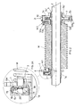
- the device of the invention comprises two main elements (A and B), with a torsion spring (M) placed and attached between them.
- the first element (A) consists in a bracket (1) with a hub (1a) designed to be inserted and held against the fixed shaft (2) that supports the series of rotating pulleys around which the rolling shutter is rolled.
- a pin (3) protrudes from the bracket (1), in parallel position to the axis of the shaft (2), which is used to attach one end (M1) of the spring (M).
- the second element (B) consists in a special pulley with a hub (4) designed to be inserted and held against the fixed shaft (2) that supports the series of rotating pulleys around which the rolling shutter is wound.
- a drum (5) is inserted outside the hub (4) and free to rotate in both directions, which is peripherally provided with a series of slots (6) used as fixing points for the top slate of the rolling shutter.
- the rotating drum (5) is formed of a central collar (5a) and an opposite pair of closing plates (5b and 5c), which are mutually tightened and fixed to the intermediate collar by means of a series of screws.
- Each plate (5b and 5c) is provided with a corresponding collar (5b' and 5c') inserted and free to rotate around the hub (4).
- a toothed crown (7) is obtained outside the hub (4), around which the drum (5) rotates, housing a balancing pawl designed to interfere with the toothed crown (7) in case of failure of the spring (M), in order to prevent the free, uncontrolled descending travel of the rolling shutter.
- Fig. 9 also shows the return spring (10) inserted into the pin (8a) and attached to a hole (8b) of the pawl (8) on one side and to a hole (9b) obtained in one of the housings (9).
- the two plates (5b and 5c) are provided with opposite slots (11) used to insert a pin (12) that externally protrudes on the plate (5b) in order to be attached to the other end (M2) of the spring (M), as shown in fig. 1.
- the end section (12a) of the pin (12) is inserted into an eye (13a) on the tip of a wing (13b) moulded in one piece with a collar (13), in parallel position outside the plate (5b) and inserted, around the collar (5b') with possibility to rotate freely.
- the pawl (8) is blocked in rear position (rest position) with respect to the toothed crown (7), since the return spring (10) cannot overcome the opposed thrust of the pin (12) against the pawl (8).
- the device of the invention has been designed in order to facilitate installation and replacement of the torsion spring (M).
- the device of the invention Since the replacement of a broken spring (M) involves the complete descending travel of the rolling shutter, the device of the invention has been provided with means that allow the operator in charge of installation and repair to exclude the braking action of the pawl (8), also when the pin (12) is released from the spring (M).
- the pawl (8) has been provided with a hooked head (8c), whose hook engages with the teeth (14a) of a forked appendix (14) obtained inside the collar (5a) of the drum (5).
- the pawl (8) has been provided with a flexible tongue (8d) situated near its tip (8e), designed to release the pawl (8) from the toothed crown (7) during replacement of the broken spring (M).
- the said replacement requires to lower the rolling shutter completely, whose descending travel is instead prevented by the pawl (8), being momentarily engaged with the toothed crown (7).
- teeth of the toothed crown (7) are laterally provided with small notches (15) that act as a stable housing for the tip of the flexible tongue (8d) during the turnover of the pawl (8).
- the hooked head (8c) engages and snaps with the teeth (14a) of the forked appendix (14), as shown in figs. 7 and 8.
- Fig. 8 shows the blocking position of the pawl (8) until a spring (M) is not attached to the pin (12), which is not shown in figs. 6, 7 and 8 deliberately.
- the pin (12) interferes against the partition (14b) that acts as a lever to determine the downward flexion of the forked appendix (14), thus releasing the tooth (14a) from the hooked head (8c) of the pawl (8), which moves forward under the return action of the spring (10) and stops against the pin (12) in the position shown in fig. 3.
- the device of the invention comprises a microswitch (15) designed to immediately cut out the electrical power supply of the motor, in case of a motorized shutter, as soon as the torsion spring (M) breaks.
- the microswitch (15) is housed in a protection hood (16) and is supported by a box (17) fixed to the bracket (1).
- the microswitch (15) is actuated by means of a balancing cam (18), which is provided with a hole (18a) where the pivoting pin (17a) is inserted, used to match the cam (18) with the box (17).
- the fixing pin (3) protrudes from the cam (18), which is provided with a slot (18b) on the opposite side with respect to the pin (3), which houses a sliding peg (19a) that protrudes from a cursor (19) acting on the microswitch (15).
- a return spring (20) between the cam (18) and the box (17) constantly tends to make the cam (18) oscillate in the direction in which the coupling between the slot (18b) and the peg (19a) brings the cursor (19) closer to the microswitch (15).
- the return spring (20) rotates the cam (18) and simultaneously makes the peg (19a) slide with respect to the housing slot (18b) and the fixing pin (3) inside a slot (1b) of the bracket (1).
Landscapes
- Engineering & Computer Science (AREA)
- Structural Engineering (AREA)
- Architecture (AREA)
- Civil Engineering (AREA)
- Mechanical Engineering (AREA)
- Emergency Lowering Means (AREA)
- Operating, Guiding And Securing Of Roll- Type Closing Members (AREA)
- Rolls And Other Rotary Bodies (AREA)
Applications Claiming Priority (1)
| Application Number | Priority Date | Filing Date | Title |
|---|---|---|---|
| ITMC20050089 ITMC20050089A1 (it) | 2005-09-06 | 2005-09-06 | Dispositivo di sicurezza, anti-caduta, per serrande avvolgibili, compensate con molle di torsione |
Publications (2)
| Publication Number | Publication Date |
|---|---|
| EP1760251A2 true EP1760251A2 (fr) | 2007-03-07 |
| EP1760251A3 EP1760251A3 (fr) | 2012-07-25 |
Family
ID=37600789
Family Applications (1)
| Application Number | Title | Priority Date | Filing Date |
|---|---|---|---|
| EP06425616A Withdrawn EP1760251A3 (fr) | 2005-09-06 | 2006-09-04 | Dispositif de sécurité anti-chute pour volets roulants avec ressorts de torsion |
Country Status (2)
| Country | Link |
|---|---|
| EP (1) | EP1760251A3 (fr) |
| IT (1) | ITMC20050089A1 (fr) |
Cited By (3)
| Publication number | Priority date | Publication date | Assignee | Title |
|---|---|---|---|---|
| WO2010034156A1 (fr) * | 2008-09-26 | 2010-04-01 | Tu Qiwen | Fenêtre ou porte à moustiquaire roulante éliminant la force de choc d'enroulement |
| WO2019025522A1 (fr) * | 2017-08-04 | 2019-02-07 | Assa Abloy Entrance Systems Ab | Ensemble comprenant un logement avec un mécanisme de protection contre la rupture de ressort d'équilibrage pour un système de porte, tel qu'un système de porte sectionnelle, et système de porte comprenant l'ensemble |
| IT201900017567A1 (it) * | 2019-09-30 | 2021-03-30 | Moveup S R L | Gruppo integrato per l’azionamento motorizzato di una serranda avvolgibile. |
Family Cites Families (3)
| Publication number | Priority date | Publication date | Assignee | Title |
|---|---|---|---|---|
| DE3425909A1 (de) * | 1984-01-24 | 1986-01-23 | Hörmann KG Brockhagen, 4803 Steinhagen | Federueberwachungsgeraet |
| DE9310792U1 (de) * | 1993-07-19 | 1994-05-19 | Hörmann KG Brockhagen, 33803 Steinhagen | Federüberwachungsgerät |
| EP1213428A1 (fr) * | 2000-12-07 | 2002-06-12 | Flexi-Force B.V. | Mécanisme d'arrêt de chute |
-
2005
- 2005-09-06 IT ITMC20050089 patent/ITMC20050089A1/it unknown
-
2006
- 2006-09-04 EP EP06425616A patent/EP1760251A3/fr not_active Withdrawn
Cited By (5)
| Publication number | Priority date | Publication date | Assignee | Title |
|---|---|---|---|---|
| WO2010034156A1 (fr) * | 2008-09-26 | 2010-04-01 | Tu Qiwen | Fenêtre ou porte à moustiquaire roulante éliminant la force de choc d'enroulement |
| WO2019025522A1 (fr) * | 2017-08-04 | 2019-02-07 | Assa Abloy Entrance Systems Ab | Ensemble comprenant un logement avec un mécanisme de protection contre la rupture de ressort d'équilibrage pour un système de porte, tel qu'un système de porte sectionnelle, et système de porte comprenant l'ensemble |
| US11767696B2 (en) | 2017-08-04 | 2023-09-26 | Assa Abloy Entrance Systems | Assembly comprising a housing with a balancing spring break protection mechanism for a door system such as a sectional door system and a door system including the assembly |
| IT201900017567A1 (it) * | 2019-09-30 | 2021-03-30 | Moveup S R L | Gruppo integrato per l’azionamento motorizzato di una serranda avvolgibile. |
| EP3798406A1 (fr) | 2019-09-30 | 2021-03-31 | Moveup S.r.l. | Ensemble intégré pour le fonctionnement motorisé d'un volet roulant |
Also Published As
| Publication number | Publication date |
|---|---|
| EP1760251A3 (fr) | 2012-07-25 |
| ITMC20050089A1 (it) | 2007-03-07 |
Similar Documents
| Publication | Publication Date | Title |
|---|---|---|
| JP5913484B2 (ja) | 開閉装置の機械式開閉体停止装置 | |
| US20020069585A1 (en) | Drop-catch mechanism | |
| US20100005723A1 (en) | Control system and test release device for an overhead door | |
| JP2017197388A (ja) | エンドレス・ケーブル・ウインチ | |
| US4664170A (en) | Rolling firedoor | |
| JP6387137B2 (ja) | 開閉装置の開閉体停止装置 | |
| US5127490A (en) | Emergency descent device | |
| KR100995259B1 (ko) | 리코일 스타터 | |
| JP5868637B2 (ja) | 開閉装置の開閉体停止装置 | |
| JP6802546B2 (ja) | 昇降窓装置 | |
| JP5912391B2 (ja) | 開閉装置の開閉体停止装置 | |
| JP4697782B2 (ja) | 引戸自動閉止装置 | |
| TWI551770B (zh) | Sunshine shading device and its operating device | |
| JP3944513B2 (ja) | 建築用シャッターの落下防止装置 | |
| JP6621322B2 (ja) | 遮蔽装置 | |
| US3968865A (en) | Cable climber safety lock | |
| US3039573A (en) | Thermally released closer for fire doors | |
| RU2104726C1 (ru) | Устройство для страховки и передвижения по веревке | |
| JP4768370B2 (ja) | 開閉装置 | |
| JP2008179990A (ja) | 建築用シャッターの急降下停止装置 | |
| JP7549133B2 (ja) | 回転テンション手段を備える、ゲートの、また具体的にはリフティングゲートの、さらに具体的には高速作動リフティングゲートの、駆動装置のための安全システム、および当該完全システムを備えるゲート | |
| EP2017431A3 (fr) | Boîte à ressort de dispositif antichute de rideau roulant à déplacement vertical munie d'une sûreté, et éléments de sûreté correspondants | |
| JP6184533B2 (ja) | 開閉装置の開閉体停止装置 | |
| JP7805724B2 (ja) | オーバーヘッドドアの操作ロープの取付構造 | |
| US1376076A (en) | Automatic fire-shutter |
Legal Events
| Date | Code | Title | Description |
|---|---|---|---|
| PUAI | Public reference made under article 153(3) epc to a published international application that has entered the european phase |
Free format text: ORIGINAL CODE: 0009012 |
|
| AK | Designated contracting states |
Kind code of ref document: A2 Designated state(s): AT BE BG CH CY CZ DE DK EE ES FI FR GB GR HU IE IS IT LI LT LU LV MC NL PL PT RO SE SI SK TR |
|
| AX | Request for extension of the european patent |
Extension state: AL BA HR MK YU |
|
| RAP1 | Party data changed (applicant data changed or rights of an application transferred) |
Owner name: GAPOSA S.R.L. |
|
| PUAL | Search report despatched |
Free format text: ORIGINAL CODE: 0009013 |
|
| AK | Designated contracting states |
Kind code of ref document: A3 Designated state(s): AT BE BG CH CY CZ DE DK EE ES FI FR GB GR HU IE IS IT LI LT LU LV MC NL PL PT RO SE SI SK TR |
|
| AX | Request for extension of the european patent |
Extension state: AL BA HR MK RS |
|
| RIC1 | Information provided on ipc code assigned before grant |
Ipc: E06B 9/84 20060101AFI20120620BHEP Ipc: E06B 9/60 20060101ALN20120620BHEP |
|
| AKY | No designation fees paid | ||
| REG | Reference to a national code |
Ref country code: DE Ref legal event code: R108 |
|
| REG | Reference to a national code |
Ref country code: DE Ref legal event code: R108 Effective date: 20130403 |
|
| STAA | Information on the status of an ep patent application or granted ep patent |
Free format text: STATUS: THE APPLICATION IS DEEMED TO BE WITHDRAWN |
|
| 18D | Application deemed to be withdrawn |
Effective date: 20130125 |