EP1760256A1 - Système de coupe latérale pour creuser des galeries - Google Patents
Système de coupe latérale pour creuser des galeries Download PDFInfo
- Publication number
- EP1760256A1 EP1760256A1 EP05107606A EP05107606A EP1760256A1 EP 1760256 A1 EP1760256 A1 EP 1760256A1 EP 05107606 A EP05107606 A EP 05107606A EP 05107606 A EP05107606 A EP 05107606A EP 1760256 A1 EP1760256 A1 EP 1760256A1
- Authority
- EP
- European Patent Office
- Prior art keywords
- underground
- boring machine
- cutter device
- underground construction
- construction
- Prior art date
- Legal status (The legal status is an assumption and is not a legal conclusion. Google has not performed a legal analysis and makes no representation as to the accuracy of the status listed.)
- Withdrawn
Links
- 238000010276 construction Methods 0.000 claims abstract description 43
- 238000005259 measurement Methods 0.000 claims description 9
- 238000000034 method Methods 0.000 claims description 8
- 238000003801 milling Methods 0.000 claims description 3
- 239000004575 stone Substances 0.000 claims description 3
- 239000002699 waste material Substances 0.000 description 15
- 238000003860 storage Methods 0.000 description 14
- 230000015572 biosynthetic process Effects 0.000 description 7
- 238000005755 formation reaction Methods 0.000 description 7
- 239000012530 fluid Substances 0.000 description 4
- 238000007789 sealing Methods 0.000 description 3
- 230000004888 barrier function Effects 0.000 description 2
- 230000008901 benefit Effects 0.000 description 2
- 230000006835 compression Effects 0.000 description 2
- 238000007906 compression Methods 0.000 description 2
- 239000007788 liquid Substances 0.000 description 2
- 230000007246 mechanism Effects 0.000 description 2
- 230000037361 pathway Effects 0.000 description 2
- 239000011435 rock Substances 0.000 description 2
- 239000000440 bentonite Substances 0.000 description 1
- 229910000278 bentonite Inorganic materials 0.000 description 1
- SVPXDRXYRYOSEX-UHFFFAOYSA-N bentoquatam Chemical compound O.O=[Si]=O.O=[Al]O[Al]=O SVPXDRXYRYOSEX-UHFFFAOYSA-N 0.000 description 1
- 230000008859 change Effects 0.000 description 1
- 229910003460 diamond Inorganic materials 0.000 description 1
- 239000010432 diamond Substances 0.000 description 1
- 239000010438 granite Substances 0.000 description 1
- 230000014759 maintenance of location Effects 0.000 description 1
- 239000000463 material Substances 0.000 description 1
- 230000003287 optical effect Effects 0.000 description 1
- 230000009467 reduction Effects 0.000 description 1
- 239000000565 sealant Substances 0.000 description 1
Images

Classifications
-
- E—FIXED CONSTRUCTIONS
- E21—EARTH OR ROCK DRILLING; MINING
- E21D—SHAFTS; TUNNELS; GALLERIES; LARGE UNDERGROUND CHAMBERS
- E21D9/00—Tunnels or galleries, with or without linings; Methods or apparatus for making thereof; Layout of tunnels or galleries
- E21D9/003—Arrangement of measuring or indicating devices for use during driving of tunnels, e.g. for guiding machines
- E21D9/004—Arrangement of measuring or indicating devices for use during driving of tunnels, e.g. for guiding machines using light beams for direction or position control
-
- E—FIXED CONSTRUCTIONS
- E21—EARTH OR ROCK DRILLING; MINING
- E21D—SHAFTS; TUNNELS; GALLERIES; LARGE UNDERGROUND CHAMBERS
- E21D9/00—Tunnels or galleries, with or without linings; Methods or apparatus for making thereof; Layout of tunnels or galleries
- E21D9/10—Making by using boring or cutting machines
- E21D9/1006—Making by using boring or cutting machines with rotary cutting tools
- E21D9/1013—Making by using boring or cutting machines with rotary cutting tools on a tool-carrier supported by a movable boom
- E21D9/1033—Making by using boring or cutting machines with rotary cutting tools on a tool-carrier supported by a movable boom by a transversely extending boom being pivotable about a longitudinal axis
Definitions
- the invention relates generally to cutter systems for a boring hole.
- Boring holes are drilled using specialized underground boring machines. Generally a boring head of the underground boring machine is pressed against the tunnel front with large force at the same time as it is rotated.
- An example of such an underground boring machines is disclosed in the publication of the patent U.S. 5,104,262 to Forsberg et al.
- the particular feature of the underground boring machine disclosed in Forsberg is that it comprises a number of swingable arms provided with boring tools for the working of the tunnel wall outside its normal diameter. The borings tools are during boring retracted into the boring machine and protected by plates, which cover the larger part of the boring tools. When in use, the swingable arms are swung out and kept in swung out position for the working of the tunnel wall outside its normal diameter.
- a further example of a underground boring machine is shown in the publication of the patent U.S. 5,529,437 to Filipowski et al.
- the guidance system comprises a front part of the underground boring machine that reflects a laser beam emitted in a back part of the underground boring machine. Hence a direction of the front part's orientation may be determined relative to the back part of the underground boring machine.
- Boring holes may be used to access distant locations, such as for example cavities, in geological formations.
- One possible application of a boring hole is to access an underground storage area for nuclear waste.
- a demolished zone forms along cut structure, bearing micro cracks caused by the relief of the compression of the rock.
- fluids may seep through the barrier into the main shaft of the nuclear storage.
- it may also be desirable to refill a once cut area.
- refilling a once cut area causes changes in the physical characteristic of the formation in the cut area.
- the invention in general, in one aspect, relates to an underground boring machine, comprising a cutter device configured to cut an underground construction, a base vehicle, and a rotating arm comprising the cutter device, wherein the rotating arm is configured to extend and retract, wherein the underground boring machine is configured to cut a pre-defined geometry in the underground construction using the rotating arm and the cutter device.
- the invention in general, in one aspect, relates to a method for cutting an underground construction, said underground construction extending longitudinally and having lateral walls, comprising determining a pre-defined geometry for said underground construction, positioning a cutter device inside the underground construction, wherein the cutter device is positioned in a longitudinal direction of the underground construction and in lateral directions along and beyond a circumference of the underground construction as defined by the lateral walls, issuing positioning coordinates associated with the pre-defined geometry inside the lateral wall along the circumference of the underground construction, and cutting the underground construction based on the pre-defined geometry.
- Figure 1 shows an underground boring machine in accordance with one embodiment of the invention.
- FIG. 2 shows an underground boring machine with sensor measurements in accordance with one embodiment of the invention.
- Figure 3 shows a flow chart for using an underground boring machine in accordance with one embodiment of the invention.
- FIGS 4A-4C show underground geometries in accordance with one embodiment of the invention.
- Embodiments of the invention relate to a underground boring machine capable of cutting 3D geometries precisely into any underground construction. Further, embodiments of the invention relate to a underground boring machine capable of refilling/sealing underground constructions to avoid fluid leakage.
- Fig. 1 shows an underground boring machine (100) in accordance with one embodiment of the invention.
- the underground boring machine includes a precisely steerable cutter (102) and is configured to cut 3D geometry into any underground construction, e.g., a tunnel, a mine shaft, a disposable cavern, etc.
- the underground construction extends longitudinally and includes lateral walls.
- the underground boring machine (100) includes a base vehicle (104) running on chains, wheels, and rails, and a rotating arm (106) on the rear face.
- the arm (106) is equipped with a stone cutting device (102) (i.e., a cutter) configured to cut in a radial direction and an axial direction.
- a stone cutting device (102) i.e., a cutter
- the base vehicle (104) and the rotating arm (106) function as a positioning device that allows the underground boring machine to position the cutter device in a longitudinal direction of the underground construction and in lateral directions along and beyond a circumference of the underground construction as defined by the lateral walls of the underground construction.
- the cutting mechanisms used on the cutter (102) of the underground boring machine (100) may be a chain saw, a multi disc saw (i.e., with a number of diamond saw blades in a row), a milling head cutter, a single cutter, etc.
- the cutting mechanism may be changed during operation of the underground boring machine (100) to allow for the best possible cutting for a given shape.
- the rotating arm (106) is extendable/retractable during rotation.
- the arm (106) may be used to cut any geometry that is capable of being described using polar coordinates.
- any geometry describable in cylindrical coordinates may be cut.
- the underground boring machine (100) is equipped with a computerized numerical control (CNC) to obtain precise geometries.
- CNC computerized numerical control
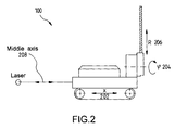
- Figure 2 shows the underground boring machine (100) including sensor measurements in accordance with one embodiment of the invention.
- the sensors on the underground boring machine detect the position of the machine (i.e., x-coordinate (202)), the rotation angle of the rotating arm (i.e., ⁇ -coordinate (204)), and the extension of the rotating arm ( i.e., R-coordinate (206)).
- sensors may be lasers pointing at a target area on the machine.
- the interference between the original laser beam and the reflected laser beam may then be used to obtain precision length measurements.
- the middle axis of the machine i.e., 208 shown in Figure 2
- an interferometer measurement may be used to determine the position of the machine.
- the ⁇ -coordinate (204) may be calculated using an incremental angle measurement (i.e., an optical disc or magnetic disc) to trace the absolute angle of rotation of the arm.
- the R-coordinate (206) may be calculated using any analog or digital length measurement, such as a wire resistor, to trace the extension of the arm.
- sensors may be any computer controllable device, such as accelerometers.
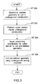
- FIG. 3 shows a flow chart for using the underground boring machine to cut an underground construction, in accordance with one embodiment of the invention.
- a precise geometry is determined (Step 300). Specifically, the precise shape of how to cut the underground construction is pre-defined, prior to using the underground boring machine to cut the underground construction.
- a cutter device is positioned inside the underground construction (Step 302). In one embodiment of the invention, the cutter device is positioned in a longitudinal direction of the underground construction and in lateral directions along and beyond a circumference of the underground construction as defined by the lateral walls.
- the CNC-control of the underground boring machine is used. Specifically, the sensors measuring the position of the base vehicle, the rotation angle of the arm of the underground boring machine, and the extension of the arm are used to exactly position the cutter device in the underground construction.
- positioning coordinates associated with the pre-defined geometry are issued to the cutter device (Step 304), so that the cutter device is able to cut the underground construction according to the precise pre-defined geometry desired (Step 306).
- polar coordinates may be issued to the cutter device to enable the cutter device to cut the precise pre-defined geometry based on the polar coordinates.
- nuclear waste storages i.e., tunnels, disposable caverns, mine shafts, etc.
- a problem with nuclear waste storage is the formation of a demolished zone in the cut structure, which bears micro cracks caused by the relief of the compression of the rock.
- a border is created between the equalized stress level inside the formation and the zero stress level at the surface of the tunnel.
- the stress gradient relieves itself with the distance to the tunnel wall, creating cracks.
- the cracks form a pathway for fluids along the tunnel.
- the demolished zone is between 20 centimeters and 1.5 meters in depth, depending on the type of formation (i.e., granite, claystone, etc.).
- channels i.e., slots
- the wall of the nuclear waste storage e.g., a tunnel
- two channels are cut into the wall of the nuclear waste storage for redundancy.
- the channels may be filled with a material that forms an impermeable filter when exposed to liquid under differential pressure, such as bentonite, which expands when exposed to liquid and thus forms a seal.
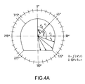
- Figs. 4A-4C show examples of underground geometries as a closure for a nuclear waste storage.
- Fig. 4A shows the different shapes and geometries that the underground boring machine is capable of cutting.
- the rotating arm with variable length can describe any shape by combining the rotation angle (i.e., ⁇ 1 ⁇ 2 , ⁇ 3 , etc.) with the extension ( i.e., r 1 , r 2 , r 3 ).
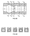
- the aforementioned measurements, combined with the position of the underground boring machine (i.e., the x-coordinate) describe the whole structure using three coordinates, as shown in Fig. 4B.
- the geometry of the cutting structure shown in Fig. 4B may be used to create a barrier for fluids that may seep into the main shaft of the nuclear waste storage.
- a deep trench may be cut circumferential around the tunnel to break through the demolished zone and fill the trench with a sealant.
- the cutting structure profile includes a gradual increase in the tunnel diameter, followed by a sharp reduction in diameter.
- this change in diameter provides a positive stop for a concrete or other plug to seal the tunnel, and is used to dissipate resulting stress from internal overpressure into the formation of the nuclear waste storage.
- Fig. 4B two such plug stops zones exist.
- Fig. 4C may be necessary to build anchors to close the underground nuclear storage against possible pressure caused by the nuclear waste (i.e., to prevent the pressure from breaking through into the main shaft).
- the anchors are built such that they fit into their spacing very tightly to gain the maximum proofing from pressure caused by the nuclear waste.
- the labeled lines in Fig. 4B indicate where each anchor may be placed in one embodiment of the invention.
- the first anchor shown in Fig. 4C (A-A) may be placed in the cross section A-A shown in Fig. 4B
- the second anchor B-B of Fig. 4C may be placed in the cross section B-B of Fig. 4B, etc.
- Fig. 4B shows a horizontal cutting structure cut by the underground boring machine
- a vertical cutting structure may also be cut using the underground boring machine.
- the sensors and position of the underground boring machine would have to be modified to guide the cutting of a vertical structure.
Landscapes
- Engineering & Computer Science (AREA)
- Mining & Mineral Resources (AREA)
- Environmental & Geological Engineering (AREA)
- Life Sciences & Earth Sciences (AREA)
- General Life Sciences & Earth Sciences (AREA)
- Geochemistry & Mineralogy (AREA)
- Geology (AREA)
- Excavating Of Shafts Or Tunnels (AREA)
Priority Applications (1)
| Application Number | Priority Date | Filing Date | Title |
|---|---|---|---|
| EP05107606A EP1760256A1 (fr) | 2005-08-18 | 2005-08-18 | Système de coupe latérale pour creuser des galeries |
Applications Claiming Priority (1)
| Application Number | Priority Date | Filing Date | Title |
|---|---|---|---|
| EP05107606A EP1760256A1 (fr) | 2005-08-18 | 2005-08-18 | Système de coupe latérale pour creuser des galeries |
Publications (1)
| Publication Number | Publication Date |
|---|---|
| EP1760256A1 true EP1760256A1 (fr) | 2007-03-07 |
Family
ID=37640796
Family Applications (1)
| Application Number | Title | Priority Date | Filing Date |
|---|---|---|---|
| EP05107606A Withdrawn EP1760256A1 (fr) | 2005-08-18 | 2005-08-18 | Système de coupe latérale pour creuser des galeries |
Country Status (1)
| Country | Link |
|---|---|
| EP (1) | EP1760256A1 (fr) |
Cited By (4)
| Publication number | Priority date | Publication date | Assignee | Title |
|---|---|---|---|---|
| FR2934007A1 (fr) * | 2008-07-17 | 2010-01-22 | Ecole Polytech | Procede de construction d'une galerie souterraine ou d'un puits permettant de realiser un bouchon etanche pour un stockage de dechets dangereux et notamment radioactifs. |
| CN110053172A (zh) * | 2019-04-23 | 2019-07-26 | 中铁十一局集团第五工程有限公司 | 隧道用悬臂式万向切割机构、设备及切割方法 |
| WO2020211276A1 (fr) * | 2019-04-19 | 2020-10-22 | 中国矿业大学 | Foreuse de tunnel de roche dure utilisant une fraise-mère rotative à entraînement |
| CN114109430A (zh) * | 2021-11-30 | 2022-03-01 | 中国矿业大学 | 一种硬岩切割截割两用掘进机 |
Citations (9)
| Publication number | Priority date | Publication date | Assignee | Title |
|---|---|---|---|---|
| US4185873A (en) * | 1977-06-11 | 1980-01-29 | Bochumer Eisenhutte Heintzmann Gmbh & Co. | Machine for mechanically advancing clean cut underground mining galleries of various profiles |
| US4655507A (en) * | 1984-05-21 | 1987-04-07 | Joy Manufacturing Company | Continuous miner |
| EP0394806A1 (fr) * | 1989-04-28 | 1990-10-31 | TREVI S.p.A. | Procédé et dispositif pour l'exécution de tunnels |
| US5104262A (en) | 1989-06-30 | 1992-04-14 | Atlas Copco Construction And Mining Technique Ab | Tunnel boring machine |
| US5529437A (en) | 1994-09-13 | 1996-06-25 | Filipowski; Mark S. | Guidance system and method for keeping a tunnel boring machine continuously on a plan line |
| WO1996019639A1 (fr) * | 1994-12-19 | 1996-06-27 | Hdrk Mining Research Limited | Commande automatique de machine servant a excaver galeries, tunnels, chambres, cavernes ou analogues |
| WO1996024753A1 (fr) * | 1995-02-07 | 1996-08-15 | Advanced Technology For Rock Excavation Inc. | Systeme de commande en continu pour une machine miniere ou de perçage de tunnels |
| US6349249B1 (en) * | 1998-04-24 | 2002-02-19 | Inco Limited | Automated guided apparatus suitable for toping applications |
| US20040207247A1 (en) * | 2002-10-15 | 2004-10-21 | Eric Jackson | Automated excavation machine |
-
2005
- 2005-08-18 EP EP05107606A patent/EP1760256A1/fr not_active Withdrawn
Patent Citations (9)
| Publication number | Priority date | Publication date | Assignee | Title |
|---|---|---|---|---|
| US4185873A (en) * | 1977-06-11 | 1980-01-29 | Bochumer Eisenhutte Heintzmann Gmbh & Co. | Machine for mechanically advancing clean cut underground mining galleries of various profiles |
| US4655507A (en) * | 1984-05-21 | 1987-04-07 | Joy Manufacturing Company | Continuous miner |
| EP0394806A1 (fr) * | 1989-04-28 | 1990-10-31 | TREVI S.p.A. | Procédé et dispositif pour l'exécution de tunnels |
| US5104262A (en) | 1989-06-30 | 1992-04-14 | Atlas Copco Construction And Mining Technique Ab | Tunnel boring machine |
| US5529437A (en) | 1994-09-13 | 1996-06-25 | Filipowski; Mark S. | Guidance system and method for keeping a tunnel boring machine continuously on a plan line |
| WO1996019639A1 (fr) * | 1994-12-19 | 1996-06-27 | Hdrk Mining Research Limited | Commande automatique de machine servant a excaver galeries, tunnels, chambres, cavernes ou analogues |
| WO1996024753A1 (fr) * | 1995-02-07 | 1996-08-15 | Advanced Technology For Rock Excavation Inc. | Systeme de commande en continu pour une machine miniere ou de perçage de tunnels |
| US6349249B1 (en) * | 1998-04-24 | 2002-02-19 | Inco Limited | Automated guided apparatus suitable for toping applications |
| US20040207247A1 (en) * | 2002-10-15 | 2004-10-21 | Eric Jackson | Automated excavation machine |
Cited By (7)
| Publication number | Priority date | Publication date | Assignee | Title |
|---|---|---|---|---|
| FR2934007A1 (fr) * | 2008-07-17 | 2010-01-22 | Ecole Polytech | Procede de construction d'une galerie souterraine ou d'un puits permettant de realiser un bouchon etanche pour un stockage de dechets dangereux et notamment radioactifs. |
| WO2010007305A3 (fr) * | 2008-07-17 | 2010-03-18 | Ecole Polytechnique | Procede de construction d'une galerie souterraine ou d'un puits permettant de realiser un bouchon etanche pour un stockage de dechets dangereux et notamment radioactifs |
| WO2020211276A1 (fr) * | 2019-04-19 | 2020-10-22 | 中国矿业大学 | Foreuse de tunnel de roche dure utilisant une fraise-mère rotative à entraînement |
| US11199092B2 (en) | 2019-04-19 | 2021-12-14 | China University Of Mining And Technology | Hard rock roadway and tunnel boring machine with actively rotating hobs |
| CN110053172A (zh) * | 2019-04-23 | 2019-07-26 | 中铁十一局集团第五工程有限公司 | 隧道用悬臂式万向切割机构、设备及切割方法 |
| CN114109430A (zh) * | 2021-11-30 | 2022-03-01 | 中国矿业大学 | 一种硬岩切割截割两用掘进机 |
| CN114109430B (zh) * | 2021-11-30 | 2024-05-03 | 中国矿业大学 | 一种硬岩切割截割两用掘进机 |
Similar Documents
| Publication | Publication Date | Title |
|---|---|---|
| KR101907751B1 (ko) | 워터젯 유닛을 적용한 tbm 커터헤드, tbm 장비 및 이를 이용한 터널공법 | |
| CA2885500C (fr) | Systeme et procede de determination de parametres de forage sur base de la pression hydraulique associee a un systeme de forage directionnel | |
| RU2713542C2 (ru) | Буровое долото с выдвижными калибрующими площадками | |
| EP3366844B1 (fr) | Dispositifs de mesures pour un site d'excavation | |
| JP5189866B2 (ja) | シールド掘進機の掘削断面土層判定装置および判定方法 | |
| BRPI0916187B1 (pt) | Ferramenta para perfuração de terra e método para perfurar material de revestimento disposto em formação subterrânea | |
| SA517381959B1 (ar) | جهاز وطريقة لحفر ثقب حفر إتجاهي في الأرض | |
| CN110005467B (zh) | 隧洞掌子面监测及优化设计方法 | |
| CA2138461A1 (fr) | Commande automique d'une machine utilisee pour creuser des galeries en direction, des tunnels, des chambres et des cavernes, ou pour excavations du meme genre | |
| US20200003011A1 (en) | Directional drilling systems and methods | |
| US10267093B2 (en) | Drilling tool including multi-step depth of cut control | |
| JP7496916B1 (ja) | 管理土圧の設定システム | |
| CN205206834U (zh) | 适合复杂硬岩地质的隧道掘进机刀盘 | |
| CN110608835B (zh) | 岩土勘探工程软岩地应力测试装置和软岩地应力测试方法 | |
| CN109538222A (zh) | 盾构机掘进稳定装置 | |
| JP5186417B2 (ja) | 拡底バケット | |
| CN111980717B (zh) | 一种盾构机盾壳注浆包裹物的处理方法 | |
| JP7648810B1 (ja) | 切羽近傍性状計測装置 | |
| CN111577303B (zh) | 适用于不同地层和埋深的盾构机掘进是否安全的计算方法 | |
| JP2010013894A (ja) | チャンバ内土砂流動計測装置及びシールド掘進機 | |
| CN209483350U (zh) | 盾构机掘进稳定装置 | |
| US5967232A (en) | Borehole-conformable tool for in-situ stress measurements | |
| JP7712503B1 (ja) | 土圧の管理システム | |
| JP7648811B1 (ja) | 管理土圧の設定システム | |
| JPH0452397A (ja) | シールド機の掘進制御方法 |
Legal Events
| Date | Code | Title | Description |
|---|---|---|---|
| PUAI | Public reference made under article 153(3) epc to a published international application that has entered the european phase |
Free format text: ORIGINAL CODE: 0009012 |
|
| AK | Designated contracting states |
Kind code of ref document: A1 Designated state(s): AT BE BG CH CY CZ DE DK EE ES FI FR GB GR HU IE IS IT LI LT LU LV MC NL PL PT RO SE SI SK TR |
|
| AX | Request for extension of the european patent |
Extension state: AL BA HR MK YU |
|
| AKX | Designation fees paid | ||
| REG | Reference to a national code |
Ref country code: DE Ref legal event code: 8566 |
|
| STAA | Information on the status of an ep patent application or granted ep patent |
Free format text: STATUS: THE APPLICATION IS DEEMED TO BE WITHDRAWN |
|
| 18D | Application deemed to be withdrawn |
Effective date: 20070908 |