EP1760259A2 - Blockierungsvorrichtung einen axialen Retentionsring einer Schaufel - Google Patents
Blockierungsvorrichtung einen axialen Retentionsring einer Schaufel Download PDFInfo
- Publication number
- EP1760259A2 EP1760259A2 EP06119582A EP06119582A EP1760259A2 EP 1760259 A2 EP1760259 A2 EP 1760259A2 EP 06119582 A EP06119582 A EP 06119582A EP 06119582 A EP06119582 A EP 06119582A EP 1760259 A2 EP1760259 A2 EP 1760259A2
- Authority
- EP
- European Patent Office
- Prior art keywords
- hook
- immobilization
- ring
- slot
- hooks
- Prior art date
- Legal status (The legal status is an assumption and is not a legal conclusion. Google has not performed a legal analysis and makes no representation as to the accuracy of the status listed.)
- Granted
Links
Images
Classifications
-
- F—MECHANICAL ENGINEERING; LIGHTING; HEATING; WEAPONS; BLASTING
- F01—MACHINES OR ENGINES IN GENERAL; ENGINE PLANTS IN GENERAL; STEAM ENGINES
- F01D—NON-POSITIVE DISPLACEMENT MACHINES OR ENGINES, e.g. STEAM TURBINES
- F01D5/00—Blades; Blade-carrying members; Heating, heat-insulating, cooling or antivibration means on the blades or the members
- F01D5/30—Fixing blades to rotors; Blade roots ; Blade spacers
- F01D5/3007—Fixing blades to rotors; Blade roots ; Blade spacers of axial insertion type
- F01D5/3015—Fixing blades to rotors; Blade roots ; Blade spacers of axial insertion type with side plates
Definitions
- the present invention relates to the technical field of rings for axial retention of the blades of a rotor of a turbomachine, in particular an aircraft engine.
- turbomachine for example an aircraft engine, equipped with such a device for immobilizing rotation.
- axial refers to the axial direction of the turbomachine.
- a turbomachine rotor is equipped with a disk and vanes carried by the disk, as well as with a retention ring to prevent movement of the vanes in the axial direction, as described in the document FR 2 729 709-A1 .
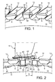
- Figure 1 illustrates such a blade retention ring of a rotor, known from the prior art.
- a disk 10 of a rotor has a disk body 11 and teeth 12 which extend radially from the disk body 11 and are distributed over the circumference thereof.
- the space between two successive teeth 12 forms a cell 13 oriented axially.
- Each tooth 12 is provided with at least one hook 6 projecting in an axial direction, which defines on this tooth an elementary groove opening radially inwards.
- the teeth 12 are provided with an upstream hook 6 and a downstream hook 6.
- FIG. 2 illustrates a root 14 of a blade 16 inserted into such a cell 13.
- the two teeth 12 make it possible to contain this blade 16 circumferentially and radially.
- a retention ring 20 is placed in a groove 22, discontinuous, which corresponds to the succession of elementary grooves.
- the presence of the retaining ring 20 in the groove 22 makes it possible to prevent axial displacement of the blades 16.
- the retaining ring 20 is opened by a slot 24 which separates the two ends or strands 26 thereof.
- the slot 24 of the retaining ring 20 is located at one of the teeth 12 and not between two adjacent teeth 12, in order to prevent the ends of the retention ring 20 from coming out. of the groove 22.
- the retaining ring 20 it is known to provide the retaining ring 20 with a device for immobilizing rotation, which ensures that the slot 24 remains positioned at the level of one tooth 12 once the retention ring 20 has been installed in the groove 22.
- each contact face 32 of the respective cleats 30 is in abutment against one of the lateral faces 44 of the abutment hook 60.
- the slot 24 becomes is located under the stopper hook 60 and the retaining ring 20 is prevented from rotating in the groove 22, so that the retaining ring 20 can not spontaneously exit the groove 22 during operation of the turbomachine. It follows that the vanes 16 can not escape from the cells 13 into which their feet 14 are inserted.
- the width D of the stopper hook 60 is reduced, because of the machining of this stopper hook 60 on its two lateral sides.
- the overlap of the slot 24 of the retaining ring 20 by the stopper hook 60 is a distance which is equal to the width D of the hook stop 60, and there is a risk that one of the two ends 26, or both ends 26, of the retaining ring 20 escapes from the elementary groove of the tooth 12 having the stopper hook 60.
- This risk is increased when the slot 24 of the retaining ring 20 is oriented obliquely to the circumferential direction of the retaining ring 20, and not perpendicular to this direction. As a result, there could be an axial displacement of a blade 14, and consequently the loss of this blade 14.
- the present invention provides a device for immobilizing in rotation a retaining ring of the blades of a rotor of a turbomachine, which overcomes the disadvantage mentioned above inherent to the rotation immobilization device of the prior art.
- the invention relates to an immobilization device in rotation of a blade retention ring on a rotor disk of a turbomachine in a substantially axial direction of said turbomachine, said rotor disk being provided with hooks distributed over its circumference and defining a groove for receiving said retention ring, including a first immobilizing hook, a second immobilizing hook and a third hook; successive immobilization means, said second immobilization hook being located between said first and third immobilizing hooks, and said retaining ring being provided with a slot, and two cleats disposed on one side thereof on each side of said slot.
- the position of said catches on said retaining ring is such that, when said retention ring is in place in said groove, said two catches abut respectively against said first immobilization hook and against said third catcher hook. immobilization, and said slot is covered by said second immobilization hook.
- immobilization hook covers two functions that are fulfilled by one and / or more of these three hooks: a stop function for a stop and a recovery function of the slot.
- said first and said third immobilization hooks each have a locking face on their side which is opposite to the opposite side of said second immobilizing hook
- said stops of said retention ring are each provided with a contact face oriented towards said slot, and said locking faces cooperate with said contact faces for an abutment of said tabs against said first and third locking hooks.
- said groove has two walls, an inner wall closest to the disc of rotor and an outer wall farthest from the rotor disc, and each locking face is located on the corresponding immobilizing hook, and extends in the axial direction from the free surface of said immobilizing hook to the inner wall of said groove.
- said locking faces are oriented in a radial plane of said rotor disk.
- said locking faces are oriented in an oblique plane with respect to a radial plane of said rotor disk.
- the invention relates to a disk / ring assembly, having a retaining ring provided with a slot, and having a rotor disk provided with hooks distributed over its circumference and defining a groove for receiving said retaining ring, characterized in that said rotor disk includes a first immobilization hook, a second immobilization hook and a third successive immobilization hook, in that said retention ring has two tabs disposed on one side thereof on each side of said slot, and in that the position of said catches on said retention ring is such that, when said retention ring is in place in said groove, said two catches abut against said first hook respectively. immobilization and against said third immobilization hook, and said slot is covered by said second immobilization hook.
- said first and said third immobilization hooks each have a locking face on their side which is opposite to the opposite side of said second immobilizing hook
- said stops of said retention ring are each provided with a contact face oriented towards said slot, and said locking faces cooperate with said contact faces for an abutment of said tabs against said first and third locking hooks.
- the invention relates to a turbomachine rotor comprising an immobilizer according to the first aspect of the invention and / or a disk / ring assembly according to the second aspect of the invention.
- the invention relates to a turbomachine, for example an aircraft engine, comprising an immobilizer according to the first aspect of the invention and / or a disk / ring assembly according to the second aspect of the invention. 'invention.
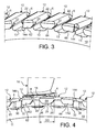
- the immobilization device in rotation according to the invention illustrated in FIGS. 3 and 4, will only be described for its differences with the immobilization device in rotation according to the prior art, illustrated in FIGS. 1 and 2.
- identical markers designate identical characteristics.
- the retention ring will simply be called “ring” and the first, second and third immobilization hooks will simply be called “First hook”, “second hook”, and “third hook” respectively.
- a disc 10 of a rotor has teeth 12 which extend radially from its circumference and are distributed over this circumference.
- the space between two successive teeth 12 forms an axially oriented cell 13 in which is inserted a foot 14 of a blade 16.
- These two successive teeth 12 have shapes and dimensions that can contain circumferentially and radially the blade 16 installed between them in cell 13.
- the teeth 12 have a protruding portion 4 protruding from the disc 10 in the upstream axial direction, and / or a protruding portion 4 protruding from the disc 10 in the axial downstream direction.
- each projecting portion 4 is formed an elementary groove opening radially inwards, the free end of each projecting portion 4 beyond the elementary groove with respect to the disk body 11 forming a hook 6 oriented radially. towards the inside.
- Each elementary groove has two walls, an inner wall closest to the rotor disk 10 and an outer wall furthest from the rotor disk 10.
- the succession of elementary grooves forms a groove 22, discontinuous, in which is disposed a ring 20.
- the ring 20 in the groove 22 constitutes an axial abutment which makes it possible to prevent axial displacement of the blades 16.
- this ring 20 is open by a slot 24 which separates its two ends 26 from one another.
- the ring 20 comprises two cleats 30 positioned on the same face thereof, on the face opposite its face facing the rotor disk 10, in the example illustrated in FIG. 2.
- each cleat 302, 304 is made in the following manner. Two cuts are made on the ring 20, so as to remove a ring sector having a given dimension in the circumferential direction of said ring 20 and the same dimension as the rest of the ring 20 in the axial direction thereof . The removed sector is replaced by a part having the same dimension in the axial direction and the same dimension in the circumferential direction, but having a greater thickness. This piece is fixed to the rest of the ring 20 by welding so as to reconstitute a closed ring 20. Then the cleat 302, 304 is machined in said piece of greater thickness than the remainder of the ring 20. Such a procedure allows precise machining of the cleats 302, 304, ensuring their dimensions and their position on the ring 20.
- the slot 24 is made on the ring 20 after the two tabs 30 are made. It is positioned in such a way that the two catches 30 are arranged towards one of the ends 26 of the ring 20, on either side of the slot 24 at a determined distance therefrom.
- the two tabs 30 are spaced apart from one another angular at least equal to three times the angular pitch of the blades 16. This angular pitch is defined as the angular difference between the median planes of two successive cells 13.
- Each tab 30 has a contact face 32 oriented towards the slot 24 of the ring 20.
- the hooks 6 are successively a first hook 62, a second hook 64 and a third hook 66.
- the second hook 64 has a geometry similar to the geometry of the hooks 6 of the prior art.
- the first hook 62 and the third hook 66 have a modified geometry with respect to the hooks 6.
- Each of the first and third hooks 62, 66 has a front face 142 which is the face of its free surface, and a side face 144 which is substantially perpendicular to the end face 142.
- the lateral face 144 of the first hook 62, respectively of the third hook 66 extends from the front face 142 of said hook 62, 66, to the inner wall of the elementary groove of said hook 62. , 66.
- the lateral face 144 of the first hook 62 is obtained by machining, on its lateral side which is opposed to its lateral side which is opposite the third hook 66.
- the lateral face 144 of the third hook 66 is obtained by machining on its lateral side which is opposed to its lateral side which is opposite the first hook 62.
- each of the corresponding teeth 12 terminates in a hook 62, 66 which has a lateral face 144 on its side opposite its opposite side of the other hook 66, 62, said lateral face 144 being circumferentially withdrawal.
- the lateral faces 144 are oriented in a radial plane of the rotor disc 10.
- the position of the two catches 30 on the ring 20 is suitably set, preferably according to the dimensions and distances of the hooks 62, 64, 66 of the rotor disk 10. This position can be defined by their respective distances from the respective ends of the ring 20 or the angular gap between them. For reasons of ease of manufacture, it is preferred, but not necessary, that the two tabs 30 are arranged symmetrically on either side of the slot 24.
- the contact face 32 of one of the catches 30 is in abutment against the lateral face 144. of the first hook 62, and the contact face 32 of the other dog 30 is in abutment against the lateral face 144 of the third hook 66.
- the lateral faces 144 are respective locking faces of the first hook 62 and the third hook 66 , which cooperate with the respective contact faces 32 of the two cleats 30 of the ring 20.
- two ends 26 of the ring 20 and the slot 24 are then under the second hook 64.
- the ring 20 is thus prevented from rotating in the groove 22. As a result, the ring 20 can not escape from the groove 22 during operation of the turbomachine. It follows that the vanes 16 can not escape in the axial direction of the cell 13 in which they are inserted.
- the invention which has just been described thus makes it possible to prevent the ring 20 from rotating in the groove 22. It has the advantage that the slot 24 of the ring 20 is positioned under a hook and not between two hooks. In addition, the slot 24 is positioned under the second hook 64, which has no recessed side face, and therefore has a width DD which is not reduced as could be the width D of the hook 60 of the device immobilization of the prior art. As a result, the risks of exit of the ends of the ring 20 out of the groove 22 are reduced.
- the actual immobilization function (by abutting the contact faces 32 of the catches against the locking faces 144 of the first and third hooks 62, 66 ) and the overlap function of the slot 24 is not provided by a single disk hook as was the case with the immobilizer of the prior art.
- the slot 24 is perpendicular to the circumferential direction of the ring 20, but it could be oblique, without departing from the scope of the invention.
- the locking faces are oriented in a radial direction of the rotor disc 10, but they could be oriented in an oblique direction with respect to a radial direction of the rotor disc 10, without leaving of the scope of the invention.
- the cells 13 into which the feet 14 of the vanes 16 are inserted are oriented axially, but the invention also applies to configurations in which the direction of the cells forms an angle with the direction axial axis of the turbomachine.
Landscapes
- Engineering & Computer Science (AREA)
- Mechanical Engineering (AREA)
- General Engineering & Computer Science (AREA)
- Turbine Rotor Nozzle Sealing (AREA)
- Structures Of Non-Positive Displacement Pumps (AREA)
- Snaps, Bayonet Connections, Set Pins, And Snap Rings (AREA)
Applications Claiming Priority (1)
| Application Number | Priority Date | Filing Date | Title |
|---|---|---|---|
| FR0552636A FR2890105A1 (fr) | 2005-08-31 | 2005-08-31 | Dispositif d'immobilisation d'un anneau de retention axiale d'une aube, disque de rotor et anneau de retention associes et rotor et motor d'aeronef les comportant |
Publications (3)
| Publication Number | Publication Date |
|---|---|
| EP1760259A2 true EP1760259A2 (de) | 2007-03-07 |
| EP1760259A3 EP1760259A3 (de) | 2007-08-01 |
| EP1760259B1 EP1760259B1 (de) | 2008-10-15 |
Family
ID=36390217
Family Applications (1)
| Application Number | Title | Priority Date | Filing Date |
|---|---|---|---|
| EP06119582A Active EP1760259B1 (de) | 2005-08-31 | 2006-08-25 | Blockierungsvorrichtung für einen axialen Retentionsring einer Schaufel |
Country Status (6)
| Country | Link |
|---|---|
| US (1) | US7540714B1 (de) |
| EP (1) | EP1760259B1 (de) |
| CA (1) | CA2558028C (de) |
| DE (1) | DE602006003156D1 (de) |
| FR (1) | FR2890105A1 (de) |
| RU (1) | RU2413847C2 (de) |
Cited By (6)
| Publication number | Priority date | Publication date | Assignee | Title |
|---|---|---|---|---|
| CN101457657B (zh) * | 2008-12-30 | 2010-12-29 | 东方电气集团东方汽轮机有限公司 | 枞树型叶根叶片的轴向定位结构 |
| FR2974142A1 (fr) * | 2011-04-14 | 2012-10-19 | Snecma | Dispositif d'immobilisation en rotation d'un anneau de retention d'aubes |
| FR2989992A1 (fr) * | 2012-04-27 | 2013-11-01 | Snecma | Dispositif d'immobilisation en rotation d'un anneau de retention d'aubes sur un disque de rotor |
| FR3000763A1 (fr) * | 2013-01-04 | 2014-07-11 | Snecma | Disque de rotor muni d’une pluralite de crochets |
| US9129390B2 (en) | 2007-06-19 | 2015-09-08 | Agfa Healthcare Nv | Method of segmenting anatomic entities in 3D digital medical images |
| EP2918785A1 (de) * | 2014-03-12 | 2015-09-16 | Rolls-Royce plc | Beschaufelter Rotor |
Families Citing this family (4)
| Publication number | Priority date | Publication date | Assignee | Title |
|---|---|---|---|---|
| FR2955904B1 (fr) * | 2010-02-04 | 2012-07-20 | Snecma | Soufflante de turbomachine |
| US8753090B2 (en) * | 2010-11-24 | 2014-06-17 | Rolls-Royce Corporation | Bladed disk assembly |
| US8864471B2 (en) | 2011-08-12 | 2014-10-21 | Hamilton Sundstrand Corporation | Gas turbine rotor with purge blades |
| EP4230843B1 (de) * | 2022-02-17 | 2025-04-30 | Siemens Energy Global GmbH & Co. KG | Rotoranordnung für einen rotor einer gasturbine |
Family Cites Families (8)
| Publication number | Priority date | Publication date | Assignee | Title |
|---|---|---|---|---|
| US4033705A (en) * | 1976-04-26 | 1977-07-05 | The United States Of America As Represented By The Administrator Of The National Aeronautics And Space Administration | Blade retainer assembly |
| US4221542A (en) * | 1977-12-27 | 1980-09-09 | General Electric Company | Segmented blade retainer |
| FR2603333B1 (fr) * | 1986-09-03 | 1990-07-20 | Snecma | Rotor de turbomachine comportant un moyen de verrouillage axial et d'etancheite d'aubes montees dans des brochages axiaux du disque et procede de montage |
| FR2694046B1 (fr) * | 1992-07-22 | 1994-09-23 | Snecma | Dispositif d'étanchéité et de rétention pour un rotor entaillé de brochages recevant des pieds d'aubes. |
| FR2729709A1 (fr) * | 1995-01-25 | 1996-07-26 | Snecma | Dispositif d'etancheite et de retention des aubes de rotor de turbomachine |
| US6234756B1 (en) * | 1998-10-26 | 2001-05-22 | Allison Advanced Development Company | Segmented ring blade retainer |
| GB0302116D0 (en) * | 2003-01-30 | 2003-03-05 | Rolls Royce Plc | A rotor |
| FR2890104A1 (fr) * | 2005-08-31 | 2007-03-02 | Snecma | Dispositif d'immobilisation d'un anneau de retention axiale d'une aube, disque de rotor et anneau de retention associes et rotor et moteur d'aeronef les comportant |
-
2005
- 2005-08-31 FR FR0552636A patent/FR2890105A1/fr not_active Withdrawn
-
2006
- 2006-08-24 US US11/466,994 patent/US7540714B1/en active Active
- 2006-08-25 DE DE602006003156T patent/DE602006003156D1/de active Active
- 2006-08-25 EP EP06119582A patent/EP1760259B1/de active Active
- 2006-08-28 CA CA2558028A patent/CA2558028C/fr active Active
- 2006-08-30 RU RU2006131299/06A patent/RU2413847C2/ru active
Cited By (8)
| Publication number | Priority date | Publication date | Assignee | Title |
|---|---|---|---|---|
| US9129390B2 (en) | 2007-06-19 | 2015-09-08 | Agfa Healthcare Nv | Method of segmenting anatomic entities in 3D digital medical images |
| CN101457657B (zh) * | 2008-12-30 | 2010-12-29 | 东方电气集团东方汽轮机有限公司 | 枞树型叶根叶片的轴向定位结构 |
| FR2974142A1 (fr) * | 2011-04-14 | 2012-10-19 | Snecma | Dispositif d'immobilisation en rotation d'un anneau de retention d'aubes |
| FR2989992A1 (fr) * | 2012-04-27 | 2013-11-01 | Snecma | Dispositif d'immobilisation en rotation d'un anneau de retention d'aubes sur un disque de rotor |
| FR3000763A1 (fr) * | 2013-01-04 | 2014-07-11 | Snecma | Disque de rotor muni d’une pluralite de crochets |
| US9689278B2 (en) | 2013-01-04 | 2017-06-27 | Snecma | Rotor disk including a plurality of hooks |
| EP2918785A1 (de) * | 2014-03-12 | 2015-09-16 | Rolls-Royce plc | Beschaufelter Rotor |
| US10138741B2 (en) | 2014-03-12 | 2018-11-27 | Rolls-Royce Plc | Bladed rotor |
Also Published As
| Publication number | Publication date |
|---|---|
| FR2890105A1 (fr) | 2007-03-02 |
| EP1760259B1 (de) | 2008-10-15 |
| EP1760259A3 (de) | 2007-08-01 |
| US7540714B1 (en) | 2009-06-02 |
| RU2006131299A (ru) | 2008-03-10 |
| US20090136349A1 (en) | 2009-05-28 |
| DE602006003156D1 (de) | 2008-11-27 |
| CA2558028C (fr) | 2013-08-13 |
| CA2558028A1 (fr) | 2007-02-28 |
| RU2413847C2 (ru) | 2011-03-10 |
Similar Documents
| Publication | Publication Date | Title |
|---|---|---|
| CA2456014C (fr) | Assemblage pour retenir un flasque annulaire contre une face radiale d'un disque | |
| EP1584794B1 (de) | Turbomaschinenrotorscheibe mit einer Axialhalterung für die Laufschaufeln | |
| CA2644335C (fr) | Etage de turbine ou de compresseur, en particulier de turbomachine | |
| CA2870102C (fr) | Etage de turbine pour une turbomachine | |
| EP1507960B1 (de) | Beschaufelte Rotorscheibe einer Turbomaschine | |
| CA2619299C (fr) | Disque de rotor de soufflante de turbomachine | |
| EP1760258B1 (de) | Blockierungsvorrichtung für einen axialen Retentionsring einer Schaufel | |
| CA2598532C (fr) | Aube de rotor d'une turbomachine | |
| EP1760259B1 (de) | Blockierungsvorrichtung für einen axialen Retentionsring einer Schaufel | |
| CA2644326C (fr) | Etage de turbine ou de compresseur d'un turboreacteur | |
| EP3433469B1 (de) | Plattform, fananordnung und fan | |
| EP3797224B1 (de) | Verbesserte fanscheibe für eine turbomaschine | |
| FR2729709A1 (fr) | Dispositif d'etancheite et de retention des aubes de rotor de turbomachine | |
| EP2060744B1 (de) | Turbinen- oder Kompressorstufe eines Turbotriebwerks | |
| FR3001505A1 (fr) | Dispositif de blocage axial d'une piece mobile par rapport a une piece de reference | |
| WO2014037653A1 (fr) | Rotor de soufflante, en particulier pour une turbomachine | |
| FR2974142A1 (fr) | Dispositif d'immobilisation en rotation d'un anneau de retention d'aubes | |
| WO2012110735A1 (fr) | Dispositif de blocage circonferentiel d'aubes pour turbomachine, a deploiement radial par mouvement de rotation d'un organe du dispositif | |
| FR3121706A1 (fr) | Clinquant a languettes pour pied d’aube de rotor de turbomachine | |
| FR3053384A1 (fr) | Ensemble de fixation d'un distributeur a un element de structure d'une turbomachine | |
| FR3164738A1 (fr) | Secteur d’étanchéité pour turbomachine | |
| FR3041381A1 (fr) | Ensemble a carter d'echappement et element aval monte par baionnette | |
| FR2903138A1 (fr) | Aube mobile et disque de rotor de turbomachine, et dispositif d'attache d'une telle aube sur un tel disque | |
| FR2989992A1 (fr) | Dispositif d'immobilisation en rotation d'un anneau de retention d'aubes sur un disque de rotor |
Legal Events
| Date | Code | Title | Description |
|---|---|---|---|
| PUAI | Public reference made under article 153(3) epc to a published international application that has entered the european phase |
Free format text: ORIGINAL CODE: 0009012 |
|
| AK | Designated contracting states |
Kind code of ref document: A2 Designated state(s): AT BE BG CH CY CZ DE DK EE ES FI FR GB GR HU IE IS IT LI LT LU LV MC NL PL PT RO SE SI SK TR |
|
| AX | Request for extension of the european patent |
Extension state: AL BA HR MK YU |
|
| PUAL | Search report despatched |
Free format text: ORIGINAL CODE: 0009013 |
|
| AK | Designated contracting states |
Kind code of ref document: A3 Designated state(s): AT BE BG CH CY CZ DE DK EE ES FI FR GB GR HU IE IS IT LI LT LU LV MC NL PL PT RO SE SI SK TR |
|
| AX | Request for extension of the european patent |
Extension state: AL BA HR MK YU |
|
| RIC1 | Information provided on ipc code assigned before grant |
Ipc: F01D 5/32 20060101AFI20070627BHEP Ipc: F01D 5/30 20060101ALI20070627BHEP Ipc: F01D 5/02 20060101ALI20070627BHEP |
|
| 17P | Request for examination filed |
Effective date: 20070906 |
|
| GRAP | Despatch of communication of intention to grant a patent |
Free format text: ORIGINAL CODE: EPIDOSNIGR1 |
|
| AKX | Designation fees paid |
Designated state(s): DE FR GB |
|
| GRAS | Grant fee paid |
Free format text: ORIGINAL CODE: EPIDOSNIGR3 |
|
| GRAA | (expected) grant |
Free format text: ORIGINAL CODE: 0009210 |
|
| AK | Designated contracting states |
Kind code of ref document: B1 Designated state(s): DE FR GB |
|
| REG | Reference to a national code |
Ref country code: GB Ref legal event code: FG4D Free format text: NOT ENGLISH |
|
| REF | Corresponds to: |
Ref document number: 602006003156 Country of ref document: DE Date of ref document: 20081127 Kind code of ref document: P |
|
| PLBE | No opposition filed within time limit |
Free format text: ORIGINAL CODE: 0009261 |
|
| STAA | Information on the status of an ep patent application or granted ep patent |
Free format text: STATUS: NO OPPOSITION FILED WITHIN TIME LIMIT |
|
| 26N | No opposition filed |
Effective date: 20090716 |
|
| REG | Reference to a national code |
Ref country code: FR Ref legal event code: PLFP Year of fee payment: 11 |
|
| REG | Reference to a national code |
Ref country code: FR Ref legal event code: PLFP Year of fee payment: 12 |
|
| REG | Reference to a national code |
Ref country code: FR Ref legal event code: CD Owner name: SAFRAN AIRCRAFT ENGINES Effective date: 20170713 |
|
| REG | Reference to a national code |
Ref country code: FR Ref legal event code: PLFP Year of fee payment: 13 |
|
| PGFP | Annual fee paid to national office [announced via postgrant information from national office to epo] |
Ref country code: DE Payment date: 20250819 Year of fee payment: 20 |
|
| PGFP | Annual fee paid to national office [announced via postgrant information from national office to epo] |
Ref country code: GB Payment date: 20250825 Year of fee payment: 20 |
|
| PGFP | Annual fee paid to national office [announced via postgrant information from national office to epo] |
Ref country code: FR Payment date: 20250827 Year of fee payment: 20 |