EP1760403B1 - Chambre de combustion pour turbine à gaz - Google Patents
Chambre de combustion pour turbine à gaz Download PDFInfo
- Publication number
- EP1760403B1 EP1760403B1 EP06254482.0A EP06254482A EP1760403B1 EP 1760403 B1 EP1760403 B1 EP 1760403B1 EP 06254482 A EP06254482 A EP 06254482A EP 1760403 B1 EP1760403 B1 EP 1760403B1
- Authority
- EP
- European Patent Office
- Prior art keywords
- passage
- steam
- nozzle
- openings
- fuel
- Prior art date
- Legal status (The legal status is an assumption and is not a legal conclusion. Google has not performed a legal analysis and makes no representation as to the accuracy of the status listed.)
- Active
Links
Images

Classifications
-
- F—MECHANICAL ENGINEERING; LIGHTING; HEATING; WEAPONS; BLASTING
- F23—COMBUSTION APPARATUS; COMBUSTION PROCESSES
- F23L—SUPPLYING AIR OR NON-COMBUSTIBLE LIQUIDS OR GASES TO COMBUSTION APPARATUS IN GENERAL ; VALVES OR DAMPERS SPECIALLY ADAPTED FOR CONTROLLING AIR SUPPLY OR DRAUGHT IN COMBUSTION APPARATUS; INDUCING DRAUGHT IN COMBUSTION APPARATUS; TOPS FOR CHIMNEYS OR VENTILATING SHAFTS; TERMINALS FOR FLUES
- F23L7/00—Supplying non-combustible liquids or gases, other than air, to the fire, e.g. oxygen, steam
- F23L7/007—Supplying oxygen or oxygen-enriched air
-
- F—MECHANICAL ENGINEERING; LIGHTING; HEATING; WEAPONS; BLASTING
- F23—COMBUSTION APPARATUS; COMBUSTION PROCESSES
- F23D—BURNERS
- F23D11/00—Burners using a direct spraying action of liquid droplets or vaporised liquid into the combustion space
- F23D11/24—Burners using a direct spraying action of liquid droplets or vaporised liquid into the combustion space by pressurisation of the fuel before a nozzle through which it is sprayed by a substantial pressure reduction into a space
-
- F—MECHANICAL ENGINEERING; LIGHTING; HEATING; WEAPONS; BLASTING
- F23—COMBUSTION APPARATUS; COMBUSTION PROCESSES
- F23D—BURNERS
- F23D11/00—Burners using a direct spraying action of liquid droplets or vaporised liquid into the combustion space
- F23D11/36—Details
- F23D11/38—Nozzles; Cleaning devices therefor
- F23D11/386—Nozzle cleaning
-
- F—MECHANICAL ENGINEERING; LIGHTING; HEATING; WEAPONS; BLASTING
- F23—COMBUSTION APPARATUS; COMBUSTION PROCESSES
- F23L—SUPPLYING AIR OR NON-COMBUSTIBLE LIQUIDS OR GASES TO COMBUSTION APPARATUS IN GENERAL ; VALVES OR DAMPERS SPECIALLY ADAPTED FOR CONTROLLING AIR SUPPLY OR DRAUGHT IN COMBUSTION APPARATUS; INDUCING DRAUGHT IN COMBUSTION APPARATUS; TOPS FOR CHIMNEYS OR VENTILATING SHAFTS; TERMINALS FOR FLUES
- F23L7/00—Supplying non-combustible liquids or gases, other than air, to the fire, e.g. oxygen, steam
- F23L7/002—Supplying water
- F23L7/005—Evaporated water; Steam
-
- F—MECHANICAL ENGINEERING; LIGHTING; HEATING; WEAPONS; BLASTING
- F23—COMBUSTION APPARATUS; COMBUSTION PROCESSES
- F23R—GENERATING COMBUSTION PRODUCTS OF HIGH PRESSURE OR HIGH VELOCITY, e.g. GAS-TURBINE COMBUSTION CHAMBERS
- F23R3/00—Continuous combustion chambers using liquid or gaseous fuel
- F23R3/02—Continuous combustion chambers using liquid or gaseous fuel characterised by the air-flow or gas-flow configuration
- F23R3/04—Air inlet arrangements
- F23R3/10—Air inlet arrangements for primary air
- F23R3/12—Air inlet arrangements for primary air inducing a vortex
- F23R3/14—Air inlet arrangements for primary air inducing a vortex by using swirl vanes
-
- F—MECHANICAL ENGINEERING; LIGHTING; HEATING; WEAPONS; BLASTING
- F23—COMBUSTION APPARATUS; COMBUSTION PROCESSES
- F23R—GENERATING COMBUSTION PRODUCTS OF HIGH PRESSURE OR HIGH VELOCITY, e.g. GAS-TURBINE COMBUSTION CHAMBERS
- F23R3/00—Continuous combustion chambers using liquid or gaseous fuel
- F23R3/28—Continuous combustion chambers using liquid or gaseous fuel characterised by the fuel supply
- F23R3/286—Continuous combustion chambers using liquid or gaseous fuel characterised by the fuel supply having fuel-air premixing devices
-
- F—MECHANICAL ENGINEERING; LIGHTING; HEATING; WEAPONS; BLASTING
- F23—COMBUSTION APPARATUS; COMBUSTION PROCESSES
- F23R—GENERATING COMBUSTION PRODUCTS OF HIGH PRESSURE OR HIGH VELOCITY, e.g. GAS-TURBINE COMBUSTION CHAMBERS
- F23R3/00—Continuous combustion chambers using liquid or gaseous fuel
- F23R3/28—Continuous combustion chambers using liquid or gaseous fuel characterised by the fuel supply
- F23R3/36—Supply of different fuels
-
- F—MECHANICAL ENGINEERING; LIGHTING; HEATING; WEAPONS; BLASTING
- F23—COMBUSTION APPARATUS; COMBUSTION PROCESSES
- F23D—BURNERS
- F23D2209/00—Safety arrangements
- F23D2209/30—Purging
-
- F—MECHANICAL ENGINEERING; LIGHTING; HEATING; WEAPONS; BLASTING
- F23—COMBUSTION APPARATUS; COMBUSTION PROCESSES
- F23D—BURNERS
- F23D2214/00—Cooling
-
- Y—GENERAL TAGGING OF NEW TECHNOLOGICAL DEVELOPMENTS; GENERAL TAGGING OF CROSS-SECTIONAL TECHNOLOGIES SPANNING OVER SEVERAL SECTIONS OF THE IPC; TECHNICAL SUBJECTS COVERED BY FORMER USPC CROSS-REFERENCE ART COLLECTIONS [XRACs] AND DIGESTS
- Y02—TECHNOLOGIES OR APPLICATIONS FOR MITIGATION OR ADAPTATION AGAINST CLIMATE CHANGE
- Y02E—REDUCTION OF GREENHOUSE GAS [GHG] EMISSIONS, RELATED TO ENERGY GENERATION, TRANSMISSION OR DISTRIBUTION
- Y02E20/00—Combustion technologies with mitigation potential
- Y02E20/34—Indirect CO2mitigation, i.e. by acting on non CO2directly related matters of the process, e.g. pre-heating or heat recovery
Definitions
- This invention relates generally to gas turbine engines and, more particularly, to a combustor for a gas turbine engine.
- JP H09 119638 A relates to a fuel nozzle for a gas turbine engine.
- the fuel nozzle has a steam injection bypass hole for mixing water vapour into the combustion air.
- At least one known industrial gas turbine application includes a steam injection system that is configured to inject steam into the combustor to facilitate reducing nitrous oxide emissions from the gas turbine engine.
- a steam injection system that is configured to inject steam into the combustor to facilitate reducing nitrous oxide emissions from the gas turbine engine.
- at least one known gas turbine engine utilizes at least one of an air or fuel purge to reduce the potential for cross-talk between adjacent fuel nozzles and/or to reduce backflow into the fuel nozzle caused by off-board steam system leakage.
- Cross-talk as used herein is defined as the inflow through a first fuel nozzle and outflow through a second fuel nozzle caused by a circumferential pressure distribution within the combustor.
- At least one known gas turbine engine includes a relatively large steam circuit flow area, such that compressor discharge bleed air supply is insufficient to purge the fuel nozzles.
- utilizing gas to purge the fuel nozzle results in a relatively small purge flow, which is insufficient to provide protection against the aforementioned situations.
- the invention provides a combustor for a gas turbine according to claim 1.
- a gas turbine engine assembly according to claim 5 is provided.
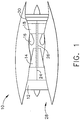
- Figure 1 is a schematic illustration of an exemplary gas turbine engine 10 including a low pressure compressor 12, a high pressure compressor 14, and a combustor 16.
- Engine 10 also includes a high pressure turbine 18, and a low pressure turbine 20 arranged in a serial, axial flow relationship.
- Compressor 12 and turbine 20 are coupled by a first shaft 24, and compressor 14 and turbine 18 are coupled by a second shaft 26.
- gas turbine engine 10 is an LMS100 engine commercially available from General Electric Company, Cincinnati, Ohio.
- Compressed air is supplied from low pressure compressor 12 to high pressure compressor 14.
- Highly compressed air is then delivered to combustor assembly 16 where it is mixed with fuel and ignited.
- Combustion gases are channeled from combustor assembly 16 to drive turbines 18 and 20.
- FIG. 2 is a cross-sectional view of a combustor, such as combustor 16, that may be used with gas turbine engine 10.
- Combustor 16 includes an inner liner 30 and an outer liner 32. Inner and outer liners 30 and 32 are joined at an upstream end 36 by a dome assembly 40.
- the cross section shown in Figure 2 is taken through one of a plurality of swirler assemblies 42 that are mounted on dome assembly 40.
- a fuel line 44 delivers fuel to a fuel nozzle 46 that supplies fuel to an inlet 48 of swirler assembly 42. Fuel is mixed with air in swirler assembly 42 and the fuel/air mixture is introduced into combustor 16 from an outlet 50 of swirler assembly 42.
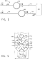
- FIG 3 is a schematic illustration of an exemplary fuel delivery system 60 that can be used with a gas turbine engine, such as gas turbine engine 10 (shown in Figure 1 ).
- fuel delivery system 60 includes a steam circuit 62 and a gas circuit 64 which respectively deliver a first gas, i.e. steam, and a first fuel, i.e. gas, to gas turbine engine 10.
- Steam circuit 62 and gas circuit 64 are both metered and sized to achieve a pressure ratio within fuel delivery system 60 appropriate for the gas being delivered to gas turbine engine 10.
- Steam circuit 62 delivers a metered steam flow to gas turbine engine 10 and gas circuit 64 delivers a metered first gas flow to gas turbine engine 10.
- Steam circuit 62 includes a connecting line 66 which extends from a metering valve (not shown) to a first manifold 70.
- the metering valve is positioned between a steam supply source (not shown) and connecting line 66.
- the first gas supply source is a steam supply source.
- First manifold 70 is connected to a connecting line 72 which extends from manifold 70 to a plurality of fuel nozzles, such as fuel nozzle 46, shown in Figure 2 .
- Fuel nozzles 46 are coupled to gas turbine engine 10 and deliver the secondary steam and secondary gas flows to gas turbine engine 10 once gas turbine engine 10 has been operating for a predetermined length of time and is being accelerated from the initial idle speed.
- Gas circuit 64 includes a connecting line 80 which extends from a metering valve (not shown) to a second manifold 82.
- the metering valve is positioned between a gas supply source (not shown) and connecting line 80.
- the gas supply source is a natural gas supply source.
- gas supply source is a liquid fuel source.
- Second manifold 82 is coupled to fuel line 44 which extends from manifold 82 to fuel nozzle 46.
- Fuel nozzles 46 are coupled to gas turbine engine 10 to deliver the first fuel to gas turbine engine 10 during initial operation of gas turbine engine 10 and while gas turbine engine 10 is operating during all operational conditions.
- fuel delivery system 60 is capable of delivering the steam and gas such that gas turbine engine 10 is capable of operating during all operational conditions.
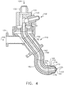
- FIG 4 is a cross-sectional view of an exemplary fuel nozzle 100 that can be used with gas turbine engine 10 and system 60 (shown in Figure 3).
- Figure 5 is an end view of a portion of fuel nozzle 100 (shown in Figure 4 ).
- Nozzle 100 includes a first fuel inlet 102, a second fuel inlet 104, and a steam inlet 106.
- first and second fuel inlets 102 and 104 are coupled to gas circuit 64
- steam inlet 106 is coupled to steam circuit 62.
- Fuel nozzle 100 also includes a nozzle body 110, and a nozzle tip 112.
- Nozzle body 110 has a first end 120 and a second end 122.
- First fuel inlet 102, second fuel inlet 104, and steam inlet 106 are each positioned adjacent first end 120 and nozzle tip 112 is positioned adjacent second end 122.
- first fuel inlet 102 extends from nozzle body 110 and includes a coupling 130
- second fuel inlet 104 extends from nozzle body 110 and includes a coupling 132 which permits each of first and second fuel inlets 102 and 104 to be coupled to fuel line 44 (shown in Figures 2 and 3 ).
- steam inlet 106 includes a coupling 134 which permits steam inlet 106 to be coupled to steam 72 (shown in Figure 3 ).
- nozzle body 110 includes a first wall 140 that defines a first passage 142 that is positioned approximately along a centerline axis 143 of nozzle body 110.
- first passage 142 extends from coupling 130 to nozzle tip 112 and is configured to channel fuel from coupling 130 to nozzle tip 112.
- Nozzle body 110 also includes a second wall 150.
- second wall 150 is coupled radially outwardly from first wall 140, and substantially circumscribes first wall 140 such that a second passage 152 is defined between first wall 140 and second wall 150.
- second passage 152 has a diameter 154 that is greater than a diameter 144 of first passage 142.
- Nozzle body 110 also includes a third wall 160.
- third wall 160 is coupled radially outwardly from second wall 150, and substantially circumscribes second wall 150 such that a third passage 162 is defined between second wall 150 and third wall 160. Accordingly, third passage 162 has a diameter 164 that is greater than second passage diameter 154. In the exemplary embodiment, third wall 160 forms an exterior surface 166 of nozzle body 110.
- nozzle tip 112 an end portion 167 and a body portion 168 that is coupled to and substantially circumscribes end portion 167 such that nozzle tip 112 has a substantially cylindrical cross-sectional profile.
- nozzle tip 112 includes at least one first opening 170 that is formed through end portion 167 and is positioned along centerline axis 143. More specifically, first opening 170 is configured to discharge fuel that is channeled through first passage 142, through nozzle tip end portion 167, and into combustor 16.
- Nozzle tip 112 also includes a second plurality of openings 172 that are formed through nozzle tip end portion 167, and are positioned radially outwardly from first opening 170.
- second plurality of openings 172 are configured to discharge fuel that is channeled through second passage 152, through nozzle tip end portion 167, and into combustor 16.
- Nozzle tip 112 also includes a third plurality of openings 174 that are formed through nozzle tip end portion 167, and are positioned radially outwardly from second plurality of openings 172.
- third plurality of openings 174 are configured to discharge steam that is channeled through third passage 162, through nozzle tip end portion 167, and into combustor 16.
- first, second, and third plurality of openings 170, 172, and 174 are each configured to discharge either fuel or steam, respectively, through nozzle tip 112 in a flow path that is substantially parallel with centerline axis 143.
- Nozzle tip 112 also includes a fourth plurality of openings 176 that are formed through nozzle tip body portion 168, and are positioned upstream from third plurality of openings 174.
- fourth plurality of openings 176 are configured to discharge steam that is channeled through third passage 162, through fourth plurality of openings 176, and into combustor 16.
- fourth plurality of openings 176 are configured to discharge steam through nozzle tip body portion 168 in a flow path that is positioned at a predefined angle with respect to centerline axis 143.
- fourth plurality of openings 176 a diameter 180 that is less than a diameter 182 of third plurality of openings 174 that during operation a first quantity of steam is channeled through fourth plurality of openings 176 that is less than a second quantity of steam that is channeled through third plurality of openings 174.
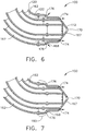
- Figure 6 is an enlarged cross-sectional view of fuel nozzle 100 (shown in Figure 4 ) during a first operational mode.
- Figure 7 is an enlarged cross-sectional view of fuel nozzle 100 (shown in Figure 4 ) during a second operational mode.
- gas turbine 10 and thus fuel nozzle 46 can be operated in either a first mode or a second mode.
- the first mode is referred to herein as an active mode, i.e. steam is channeled through fuel nozzle 100 and into combustor 16.
- the inactive or dry mode steam is not channeled through fuel nozzle 100 and into combustor 16.
- nozzle 100 when nozzle 100 is operated in the active mode (shown in Figure 6 ), steam is channeled from steam circuit 62 to nozzle 100 via coupling 134. More specifically, steam is channeled from steam circuit 62 into third passage 162. The steam is then channeled from nozzle body first end 120 to nozzle body second end 122, and thus nozzle tip 112.
- steam is channeled through openings 174 and openings 176 in combustor 16. More specifically, a first quantity of steam is channeled through openings 174 and a second quantity of steam, that is less than the first quantity of steam, is channeled through openings 176.
- openings 174 have a larger diameter than openings 176 a majority of the steam is channeled through openings 174 in the active mode. Accordingly, channeling steam through openings 174 and 176 during the active mode facilitates increasing the fuel efficiency of gas turbine engine 10.
- nozzle 100 when nozzle 100 is operated in the dry mode, steam is not channeled through nozzle 100. More specifically, when nozzle 100 is operated in the dry mode, the air pressure drop across swirler 42 generates a pressure differential between openings 174 and openings 176 such that an airflow 190 is forced through openings 176 into third passage 162 and then through openings 174. Thus, during the inactive mode, openings 176 facilitate purging fuel nozzle 100. More specifically, during dry operation, the air pressure drop across swirler 42 facilitates providing the driving pressure for a purge flow across nozzle tip 112. Moreover, through appropriate selection of the design variables, protection against circumferential pressure gradients and steam system leaks will be maintained without significantly impacting gas/steam emissions performance.
- the above described fuel nozzle for a gas turbine engine is cost-effective and reliable.
- the fuel nozzle includes a separate steam injection circuit that is positioned on the outermost annulus of the fuel nozzle.
- the nozzle stem forms the outer boundary of the steam circuit.
- the above described fuel nozzle includes a series of orifices formed through the nozzle stem immediately upstream of the swirler/nozzle interface such that during active operation a fraction of the steam exits these "upstream holes," while the remainder is injected at the tip.
- the air pressure drop across the swirler provide the driving pressure for a purge flow across the nozzle tip.
Landscapes
- Engineering & Computer Science (AREA)
- Chemical & Material Sciences (AREA)
- Combustion & Propulsion (AREA)
- Mechanical Engineering (AREA)
- General Engineering & Computer Science (AREA)
- Nozzles For Spraying Of Liquid Fuel (AREA)
- Turbine Rotor Nozzle Sealing (AREA)
- Engine Equipment That Uses Special Cycles (AREA)
Claims (5)
- Chambre de combustion (16) pour un moteur à turbine à gaz (10), la chambre de combustion comprenant une chemise interne (30) et une chemise externe (32), dans laquelle la chemise interne et la chemise externe sont jointes à une extrémité amont (36) par un ensemble formant dôme (40),
une pluralité d'ensembles de turbulence (42) montés sur l'ensemble formant dôme (40) et
une buse à carburant (46, 100) pour un moteur à turbine à gaz (10), ladite buse à carburant comprenant :un corps de buse (110) ayant un axe de symétrie (143) qui s'étend à travers celui-ci, ledit corps de buse comprenant un premier passage (142) s'étendant coaxialement à travers celui-ci, un deuxième passage (152) et un troisième passage (162), ledit deuxième passage circonscrivant ledit premier passage, ledit troisième passage étant formé radialement vers l'extérieur dudit deuxième passage ; etun embout de buse (112) couplé audit corps de buse, ledit embout de buse comprenant au moins une ouverture de décharge primaire en communication fluidique avec ledit premier passage, au moins une ouverture de décharge secondaire (172) en communication fluidique avec ledit deuxième passage, au moins une ouverture de décharge tertiaire en communication fluidique avec ledit troisième passage et une pluralité de quatrièmes ouvertures de décharge (176) en communication fluidique avec ledit troisième passage (162), ladite pluralité de quatrièmes ouvertures de décharge étant formée en amont de ladite au moins une ouverture tertiaire (174) ;dans laquelle ledit troisième passage (162) est configuré pour canaliser de la vapeur d'eau en aval à travers ladite ouverture tertiaire d'embout de buse (174) et ladite pluralité de quatrièmes ouvertures d'embout de buse (176) ;dans laquelle ladite pluralité de quatrièmes ouvertures (176) est agencée et configurée pour canaliser de l'air de refroidissement dans ledit embout de buse (112) pour purger ladite buse de carburant à travers ladite au moins une ouverture tertiaire (174) ; etdans laquelle la buse à carburant (46, 100) s'étend à travers l'entrée (48) du dispositif à turbulence avec les ouvertures primaire (170), secondaire (172) et tertiaire (174) qui s'étendent dans le dispositif à turbulence et les quatrièmes ouvertures qui sont agencées en amont de l'entrée (48) du dispositif à turbulence. - Chambre de combustion (16) selon la revendication 1, dans laquelle lesdits premier (142) et deuxième (152) passages sont configurés pour décharger du carburant en aval à travers ledit embout de buse (112) par au moins des ouvertures primaire (170) et secondaire (172).
- Chambre de combustion (16) selon la revendication 1 ou la revendication 2, dans laquelle ledit troisième passage (162) est configuré pour canaliser un premier volume de vapeur d'eau à travers ladite au moins une ouverture tertiaire (174) et un second volume de vapeur d'eau à travers ladite pluralité de quatrièmes ouvertures (176).
- Chambre de combustion (16) selon l'une quelconque des revendications précédentes, dans laquelle ledit troisième passage (162) est configuré pour canaliser un premier volume de vapeur d'eau à travers ladite au moins une ouverture tertiaire (174) et un second volume de vapeur d'eau à travers ladite pluralité de quatrièmes ouvertures (176), ledit premier volume de vapeur d'eau étant plus grand que ledit second volume de vapeur d'eau.
- Ensemble de moteur à turbine à gaz comprenant :un moteur à turbine à gaz (10) ;au moins deux distributeurs couplés audit moteur à turbine à gaz, lesdits au moins deux distributeurs comprenant un premier distributeur (70) et un second distributeur (82), ledit premier distributeur étant configuré pour délivrer un premier gaz au moteur à turbine à gaz, ledit second distributeur étant configuré pour délivrer un premier carburant au moteur à turbine à gaz ; etune chambre de combustion selon l'une quelconque des revendications précédentes, dans lequel une buse à carburant (46,100) est couplée auxdits distributeurs.
Applications Claiming Priority (1)
| Application Number | Priority Date | Filing Date | Title |
|---|---|---|---|
| US11/217,505 US7536862B2 (en) | 2005-09-01 | 2005-09-01 | Fuel nozzle for gas turbine engines |
Publications (3)
| Publication Number | Publication Date |
|---|---|
| EP1760403A2 EP1760403A2 (fr) | 2007-03-07 |
| EP1760403A3 EP1760403A3 (fr) | 2015-06-03 |
| EP1760403B1 true EP1760403B1 (fr) | 2018-10-24 |
Family
ID=37074220
Family Applications (1)
| Application Number | Title | Priority Date | Filing Date |
|---|---|---|---|
| EP06254482.0A Active EP1760403B1 (fr) | 2005-09-01 | 2006-08-29 | Chambre de combustion pour turbine à gaz |
Country Status (4)
| Country | Link |
|---|---|
| US (1) | US7536862B2 (fr) |
| EP (1) | EP1760403B1 (fr) |
| JP (1) | JP4868988B2 (fr) |
| CA (1) | CA2557047C (fr) |
Families Citing this family (43)
| Publication number | Priority date | Publication date | Assignee | Title |
|---|---|---|---|---|
| US7530231B2 (en) * | 2005-04-01 | 2009-05-12 | Pratt & Whitney Canada Corp. | Fuel conveying member with heat pipe |
| US7836699B2 (en) * | 2005-12-20 | 2010-11-23 | United Technologies Corporation | Combustor nozzle |
| US7854120B2 (en) * | 2006-03-03 | 2010-12-21 | Pratt & Whitney Canada Corp. | Fuel manifold with reduced losses |
| US7520134B2 (en) * | 2006-09-29 | 2009-04-21 | General Electric Company | Methods and apparatus for injecting fluids into a turbine engine |
| FR2908867B1 (fr) * | 2006-11-16 | 2012-06-15 | Snecma | Dispositif d'injection d'un melange d'air et de carburant, chambre de combustion et turbomachine munies d'un tel dispositif |
| US7712313B2 (en) * | 2007-08-22 | 2010-05-11 | Pratt & Whitney Canada Corp. | Fuel nozzle for a gas turbine engine |
| US20090236442A1 (en) * | 2007-12-10 | 2009-09-24 | Tdc Products B.V. | Injection device for an internal combustion engine |
| DE102008026459A1 (de) * | 2008-06-03 | 2009-12-10 | E.On Ruhrgas Ag | Brenner, insbesondere für eine Verbrennungseinrichtung in einer Gasturbinenanlage |
| US9121609B2 (en) | 2008-10-14 | 2015-09-01 | General Electric Company | Method and apparatus for introducing diluent flow into a combustor |
| US20100089022A1 (en) * | 2008-10-14 | 2010-04-15 | General Electric Company | Method and apparatus of fuel nozzle diluent introduction |
| US20100089020A1 (en) * | 2008-10-14 | 2010-04-15 | General Electric Company | Metering of diluent flow in combustor |
| US8567199B2 (en) * | 2008-10-14 | 2013-10-29 | General Electric Company | Method and apparatus of introducing diluent flow into a combustor |
| EP2196734A1 (fr) * | 2008-12-12 | 2010-06-16 | Siemens Aktiengesellschaft | Lance de combustible pour un brûleur |
| US8099940B2 (en) | 2008-12-18 | 2012-01-24 | Solar Turbines Inc. | Low cross-talk gas turbine fuel injector |
| US8479519B2 (en) * | 2009-01-07 | 2013-07-09 | General Electric Company | Method and apparatus to facilitate cooling of a diffusion tip within a gas turbine engine |
| US8555646B2 (en) * | 2009-01-27 | 2013-10-15 | General Electric Company | Annular fuel and air co-flow premixer |
| US20100192582A1 (en) | 2009-02-04 | 2010-08-05 | Robert Bland | Combustor nozzle |
| US20110072823A1 (en) * | 2009-09-30 | 2011-03-31 | Daih-Yeou Chen | Gas turbine engine fuel injector |
| US8991188B2 (en) | 2011-01-05 | 2015-03-31 | General Electric Company | Fuel nozzle passive purge cap flow |
| US8893500B2 (en) | 2011-05-18 | 2014-11-25 | Solar Turbines Inc. | Lean direct fuel injector |
| US8919132B2 (en) | 2011-05-18 | 2014-12-30 | Solar Turbines Inc. | Method of operating a gas turbine engine |
| US8448442B2 (en) * | 2011-05-19 | 2013-05-28 | General Electric Company | Flexible combustor fuel nozzle |
| US9133767B2 (en) * | 2011-08-02 | 2015-09-15 | Siemens Energy, Inc | Fuel injecting assembly for gas turbine engine including cooling gap between supply structures |
| US8984888B2 (en) * | 2011-10-26 | 2015-03-24 | General Electric Company | Fuel injection assembly for use in turbine engines and method of assembling same |
| US9182124B2 (en) | 2011-12-15 | 2015-11-10 | Solar Turbines Incorporated | Gas turbine and fuel injector for the same |
| JP5618337B2 (ja) * | 2012-02-28 | 2014-11-05 | 三菱日立パワーシステムズ株式会社 | ガスタービン燃焼器 |
| EP2877711A1 (fr) | 2012-06-15 | 2015-06-03 | General Electric Company | Conduite de fluide |
| US9400104B2 (en) | 2012-09-28 | 2016-07-26 | United Technologies Corporation | Flow modifier for combustor fuel nozzle tip |
| US9441835B2 (en) * | 2012-10-08 | 2016-09-13 | General Electric Company | System and method for fuel and steam injection within a combustor |
| US20140157788A1 (en) * | 2012-12-06 | 2014-06-12 | General Electric Company | Fuel nozzle for gas turbine |
| US9447976B2 (en) * | 2014-01-10 | 2016-09-20 | Solar Turbines Incorporated | Fuel injector with a diffusing main gas passage |
| US9874351B2 (en) * | 2015-04-14 | 2018-01-23 | General Electric Company | Thermally-coupled fuel manifold |
| US10393030B2 (en) | 2016-10-03 | 2019-08-27 | United Technologies Corporation | Pilot injector fuel shifting in an axial staged combustor for a gas turbine engine |
| US10760793B2 (en) | 2017-07-21 | 2020-09-01 | General Electric Company | Jet in cross flow fuel nozzle for a gas turbine engine |
| US11725818B2 (en) * | 2019-12-06 | 2023-08-15 | Raytheon Technologies Corporation | Bluff-body piloted high-shear injector and method of using same |
| US12098678B2 (en) | 2020-01-08 | 2024-09-24 | Rtx Corporation | Method of using a primary fuel to pilot liquid fueled combustors |
| US11920525B2 (en) * | 2022-08-05 | 2024-03-05 | Rtx Corporation | Liquid and hydrogen/methane fuel injector |
| US12546469B1 (en) * | 2022-09-23 | 2026-02-10 | Rtx Corporation | Gas turbine engine fuel injector with multiple fuel circuits |
| US11920792B1 (en) * | 2023-03-13 | 2024-03-05 | Rtx Corporation | Cooling turbine engine fuel-air mixer with steam |
| US12449126B2 (en) * | 2023-03-13 | 2025-10-21 | Rtx Corporation | Injecting fuel-steam mixture into turbine engine combustor |
| US12038177B1 (en) * | 2023-03-14 | 2024-07-16 | Rtx Corporation | Fuel injector assembly for gas turbine engine with fuel, air and steam injection |
| US12152779B1 (en) | 2023-08-22 | 2024-11-26 | General Electric Company | Combustor |
| US12422143B1 (en) | 2024-03-05 | 2025-09-23 | Rtx Corporation | Fuel-air mixer for turbine engine combustion section |
Citations (1)
| Publication number | Priority date | Publication date | Assignee | Title |
|---|---|---|---|---|
| US4854127A (en) * | 1988-01-14 | 1989-08-08 | General Electric Company | Bimodal swirler injector for a gas turbine combustor |
Family Cites Families (11)
| Publication number | Priority date | Publication date | Assignee | Title |
|---|---|---|---|---|
| US3777983A (en) * | 1971-12-16 | 1973-12-11 | Gen Electric | Gas cooled dual fuel air atomized fuel nozzle |
| JPH0639240Y2 (ja) * | 1987-12-03 | 1994-10-12 | 三菱重工業株式会社 | ガスタービン用燃焼器 |
| EP0393484B1 (fr) * | 1989-04-20 | 1992-11-04 | Asea Brown Boveri Ag | Agencement pour chambre de combustion |
| US5417054A (en) * | 1992-05-19 | 1995-05-23 | Fuel Systems Textron, Inc. | Fuel purging fuel injector |
| JP3174634B2 (ja) * | 1992-08-11 | 2001-06-11 | 三菱重工業株式会社 | ガスタービンの燃料噴射装置 |
| IT1263683B (it) * | 1992-08-21 | 1996-08-27 | Westinghouse Electric Corp | Complesso di ugello per combustibile per una turbina a gas |
| JPH09119638A (ja) * | 1995-10-25 | 1997-05-06 | Mitsubishi Heavy Ind Ltd | ガスタービン燃焼器 |
| US6393823B1 (en) * | 1999-11-05 | 2002-05-28 | General Electric Company | Methods for fuel nozzle staging for gas turbine engines |
| US6543235B1 (en) * | 2001-08-08 | 2003-04-08 | Cfd Research Corporation | Single-circuit fuel injector for gas turbine combustors |
| US7143583B2 (en) * | 2002-08-22 | 2006-12-05 | Hitachi, Ltd. | Gas turbine combustor, combustion method of the gas turbine combustor, and method of remodeling a gas turbine combustor |
| US6935117B2 (en) * | 2003-10-23 | 2005-08-30 | United Technologies Corporation | Turbine engine fuel injector |
-
2005
- 2005-09-01 US US11/217,505 patent/US7536862B2/en active Active
-
2006
- 2006-08-24 CA CA2557047A patent/CA2557047C/fr not_active Expired - Fee Related
- 2006-08-29 EP EP06254482.0A patent/EP1760403B1/fr active Active
- 2006-08-31 JP JP2006235244A patent/JP4868988B2/ja not_active Expired - Fee Related
Patent Citations (1)
| Publication number | Priority date | Publication date | Assignee | Title |
|---|---|---|---|---|
| US4854127A (en) * | 1988-01-14 | 1989-08-08 | General Electric Company | Bimodal swirler injector for a gas turbine combustor |
Also Published As
| Publication number | Publication date |
|---|---|
| EP1760403A2 (fr) | 2007-03-07 |
| CA2557047A1 (fr) | 2007-03-01 |
| JP4868988B2 (ja) | 2012-02-01 |
| US7536862B2 (en) | 2009-05-26 |
| JP2007064227A (ja) | 2007-03-15 |
| US20070044477A1 (en) | 2007-03-01 |
| EP1760403A3 (fr) | 2015-06-03 |
| CA2557047C (fr) | 2013-12-31 |
Similar Documents
| Publication | Publication Date | Title |
|---|---|---|
| EP1760403B1 (fr) | Chambre de combustion pour turbine à gaz | |
| US6871501B2 (en) | Method and apparatus to decrease gas turbine engine combustor emissions | |
| US7716931B2 (en) | Method and apparatus for assembling gas turbine engine | |
| US8099940B2 (en) | Low cross-talk gas turbine fuel injector | |
| US7520134B2 (en) | Methods and apparatus for injecting fluids into a turbine engine | |
| JP4681113B2 (ja) | 気体燃料及び液体燃料の両方を使用するガスタービンの燃料を段階的に用いるための燃料装置構成とその方法 | |
| EP2543931B1 (fr) | Appareil et systèmes relatifs à des injecteurs de carburant et passages de carburant dans des moteurs à turbine à gaz | |
| US6536206B2 (en) | Apparatus for decreasing combustor emissions | |
| US7340900B2 (en) | Method and apparatus for decreasing combustor acoustics | |
| CN102679399B (zh) | 具有固定火苗用燃料喷嘴的燃气涡轮机燃烧室 | |
| CN101793408A (zh) | 燃烧器喷嘴 | |
| JP2014077627A (ja) | 燃料ノズルとその組立方法 | |
| EP4202302A1 (fr) | Buse de combustible et tourbillonneur | |
| EP4206534B1 (fr) | Prémélangeur de carburant de turbine à gaz | |
| CA2516753A1 (fr) | Methodes et dispositif de reduction des emissions d'une turbine a gaz | |
| EP2634489A1 (fr) | Ensemble de buse de combustible destiné à être utilisé dans des moteurs à turbine et son procédé d'assemblage | |
| US12339005B2 (en) | Hydrogen fuel distributor | |
| US20240263786A1 (en) | Central air passage with radial fuel distributor |
Legal Events
| Date | Code | Title | Description |
|---|---|---|---|
| PUAI | Public reference made under article 153(3) epc to a published international application that has entered the european phase |
Free format text: ORIGINAL CODE: 0009012 |
|
| AK | Designated contracting states |
Kind code of ref document: A2 Designated state(s): AT BE BG CH CY CZ DE DK EE ES FI FR GB GR HU IE IS IT LI LT LU LV MC NL PL PT RO SE SI SK TR |
|
| AX | Request for extension of the european patent |
Extension state: AL BA HR MK YU |
|
| PUAL | Search report despatched |
Free format text: ORIGINAL CODE: 0009013 |
|
| AK | Designated contracting states |
Kind code of ref document: A3 Designated state(s): AT BE BG CH CY CZ DE DK EE ES FI FR GB GR HU IE IS IT LI LT LU LV MC NL PL PT RO SE SI SK TR |
|
| AX | Request for extension of the european patent |
Extension state: AL BA HR MK RS |
|
| RIC1 | Information provided on ipc code assigned before grant |
Ipc: F23R 3/36 20060101ALI20150427BHEP Ipc: F23R 3/28 20060101AFI20150427BHEP Ipc: F23D 11/38 20060101ALI20150427BHEP Ipc: F23L 7/00 20060101ALI20150427BHEP Ipc: F23R 3/14 20060101ALI20150427BHEP Ipc: F23D 11/24 20060101ALI20150427BHEP |
|
| 17P | Request for examination filed |
Effective date: 20151203 |
|
| RBV | Designated contracting states (corrected) |
Designated state(s): AT BE BG CH CY CZ DE DK EE ES FI FR GB GR HU IE IS IT LI LT LU LV MC NL PL PT RO SE SI SK TR |
|
| AKX | Designation fees paid |
Designated state(s): DE FR GB |
|
| AXX | Extension fees paid |
Extension state: MK Extension state: AL Extension state: HR Extension state: BA Extension state: RS |
|
| 17Q | First examination report despatched |
Effective date: 20170726 |
|
| GRAP | Despatch of communication of intention to grant a patent |
Free format text: ORIGINAL CODE: EPIDOSNIGR1 |
|
| INTG | Intention to grant announced |
Effective date: 20180620 |
|
| GRAS | Grant fee paid |
Free format text: ORIGINAL CODE: EPIDOSNIGR3 |
|
| GRAA | (expected) grant |
Free format text: ORIGINAL CODE: 0009210 |
|
| AK | Designated contracting states |
Kind code of ref document: B1 Designated state(s): DE FR GB |
|
| REG | Reference to a national code |
Ref country code: GB Ref legal event code: FG4D |
|
| REG | Reference to a national code |
Ref country code: DE Ref legal event code: R096 Ref document number: 602006056644 Country of ref document: DE |
|
| REG | Reference to a national code |
Ref country code: DE Ref legal event code: R097 Ref document number: 602006056644 Country of ref document: DE |
|
| PLBE | No opposition filed within time limit |
Free format text: ORIGINAL CODE: 0009261 |
|
| STAA | Information on the status of an ep patent application or granted ep patent |
Free format text: STATUS: NO OPPOSITION FILED WITHIN TIME LIMIT |
|
| 26N | No opposition filed |
Effective date: 20190725 |
|
| PGFP | Annual fee paid to national office [announced via postgrant information from national office to epo] |
Ref country code: DE Payment date: 20190722 Year of fee payment: 14 Ref country code: FR Payment date: 20190723 Year of fee payment: 14 |
|
| REG | Reference to a national code |
Ref country code: DE Ref legal event code: R119 Ref document number: 602006056644 Country of ref document: DE |
|
| PG25 | Lapsed in a contracting state [announced via postgrant information from national office to epo] |
Ref country code: FR Free format text: LAPSE BECAUSE OF NON-PAYMENT OF DUE FEES Effective date: 20200831 Ref country code: DE Free format text: LAPSE BECAUSE OF NON-PAYMENT OF DUE FEES Effective date: 20210302 |
|
| P01 | Opt-out of the competence of the unified patent court (upc) registered |
Effective date: 20230414 |
|
| PGFP | Annual fee paid to national office [announced via postgrant information from national office to epo] |
Ref country code: GB Payment date: 20250724 Year of fee payment: 20 |