EP1760406B1 - Rohrverteiler für eine Heizungs- oder Kühlanlage - Google Patents
Rohrverteiler für eine Heizungs- oder Kühlanlage Download PDFInfo
- Publication number
- EP1760406B1 EP1760406B1 EP06017730A EP06017730A EP1760406B1 EP 1760406 B1 EP1760406 B1 EP 1760406B1 EP 06017730 A EP06017730 A EP 06017730A EP 06017730 A EP06017730 A EP 06017730A EP 1760406 B1 EP1760406 B1 EP 1760406B1
- Authority
- EP
- European Patent Office
- Prior art keywords
- chamber
- flow
- manifold
- return
- connection
- Prior art date
- Legal status (The legal status is an assumption and is not a legal conclusion. Google has not performed a legal analysis and makes no representation as to the accuracy of the status listed.)
- Active
Links
- 238000010438 heat treatment Methods 0.000 title claims description 22
- 238000001816 cooling Methods 0.000 title claims description 8
- 238000005192 partition Methods 0.000 claims description 26
- 229910000831 Steel Inorganic materials 0.000 claims description 4
- 239000010802 sludge Substances 0.000 claims description 4
- 239000010959 steel Substances 0.000 claims description 4
- 239000013529 heat transfer fluid Substances 0.000 description 19
- 238000013461 design Methods 0.000 description 6
- 239000012530 fluid Substances 0.000 description 4
- 238000004519 manufacturing process Methods 0.000 description 4
- 238000004891 communication Methods 0.000 description 3
- 230000006978 adaptation Effects 0.000 description 1
- 230000001627 detrimental effect Effects 0.000 description 1
- 239000007788 liquid Substances 0.000 description 1
- 238000012545 processing Methods 0.000 description 1
- 238000005057 refrigeration Methods 0.000 description 1
- 238000000926 separation method Methods 0.000 description 1
Images



Classifications
-
- F—MECHANICAL ENGINEERING; LIGHTING; HEATING; WEAPONS; BLASTING
- F24—HEATING; RANGES; VENTILATING
- F24D—DOMESTIC- OR SPACE-HEATING SYSTEMS, e.g. CENTRAL HEATING SYSTEMS; DOMESTIC HOT-WATER SUPPLY SYSTEMS; ELEMENTS OR COMPONENTS THEREFOR
- F24D3/00—Hot-water central heating systems
- F24D3/10—Feed-line arrangements, e.g. providing for heat-accumulator tanks, expansion tanks ; Hydraulic components of a central heating system
- F24D3/1091—Mixing cylinders
-
- F—MECHANICAL ENGINEERING; LIGHTING; HEATING; WEAPONS; BLASTING
- F16—ENGINEERING ELEMENTS AND UNITS; GENERAL MEASURES FOR PRODUCING AND MAINTAINING EFFECTIVE FUNCTIONING OF MACHINES OR INSTALLATIONS; THERMAL INSULATION IN GENERAL
- F16L—PIPES; JOINTS OR FITTINGS FOR PIPES; SUPPORTS FOR PIPES, CABLES OR PROTECTIVE TUBING; MEANS FOR THERMAL INSULATION IN GENERAL
- F16L41/00—Branching pipes; Joining pipes to walls
- F16L41/02—Branch units, e.g. made in one piece, welded, riveted
- F16L41/03—Branch units, e.g. made in one piece, welded, riveted comprising junction pieces for four or more pipe members
-
- F—MECHANICAL ENGINEERING; LIGHTING; HEATING; WEAPONS; BLASTING
- F24—HEATING; RANGES; VENTILATING
- F24D—DOMESTIC- OR SPACE-HEATING SYSTEMS, e.g. CENTRAL HEATING SYSTEMS; DOMESTIC HOT-WATER SUPPLY SYSTEMS; ELEMENTS OR COMPONENTS THEREFOR
- F24D3/00—Hot-water central heating systems
- F24D3/10—Feed-line arrangements, e.g. providing for heat-accumulator tanks, expansion tanks ; Hydraulic components of a central heating system
- F24D3/1058—Feed-line arrangements, e.g. providing for heat-accumulator tanks, expansion tanks ; Hydraulic components of a central heating system disposition of pipes and pipe connections
- F24D3/1066—Distributors for heating liquids
Definitions
- a disadvantage is considered in this known manifold, that it can easily lead to an undesirable circulation flow in the primary circuit, whereby the heat generated is not transferred to the desired extent to the secondary circuits, ie heating circuits.
- This has the consequence that the theoretically available heat output of one or more boilers can not be supplied in full to the secondary circuits with heat consumers provided therein.
- the reason for this is, in particular, that the flow connection and the return connection of the primary circuit to the decoupling space are relatively close to each other and that the flow of heat transfer fluid entering through the flow connection in the decoupling space, is directed towards the return port of the primary or boiler circuit and so preferred in the return, ie returned to the boiler.
- the return temperature of the heat transfer fluid that reaches the boiler is thereby undesirably high, which is detrimental to the performance of the heating system.
- the DE 20 2005 005 008 U shows a manifold for a heating or cooling system with an elongated, in operation horizontally arranged housing in which a flow chamber with multiple flow ports and a return chamber with multiple return ports for multiple secondary circuits are provided. Furthermore, the manifold comprises a hydraulic switch for the hydraulic decoupling of a connected to a flow connection and a return port of the switch primary circuit of the secondary circuits, wherein the hydraulic switch is integrated into the housing and comprises a fluidically connected to the flow chamber and the return chamber switch chamber, in which Flow connection and the return connection of the primary circuit open.
- the housing as a switch chamber over at least a portion of the horizontal length of the housing extending turnout chamber is provided and the switch chamber is fluidly connected at two horizontally spaced locations on the one hand with the flow chamber and on the other hand with the return chamber.
- the functions of distributing and collecting a heat transfer fluid and the function of a hydraulic switch in a unit can be combined.
- the switch chamber must be relatively large, in particular relatively long, in order to achieve a good mixing of warmer and colder heat transfer fluid in the case of a compensation flow through the switch chamber and thus to ensure a homogeneous temperature of the heat transfer fluid in the event of the occurrence of a compensating flow ,
- Essential to the invention opens in the new manifold of the flow connection of the primary circuit no longer, as was customary in the switch chamber, but is passed through the switch chamber and then flows into the flow chamber of the secondary circuits.
- the flow connection between the switch chamber and the flow chamber is formed here by the annular passage around the pipe socket at the point where the pipe socket passes through the partition. By dimensioning the diameter and the shape of this opening and the outer diameter of the pipe socket, the cross section of the annular passage can be constructive be determined.
- the concentric arrangement of the pipe socket in the opening in the partition also ensures that advantageously the secondary circuit-side compensating flow takes place in the form of a concentric annular gap flow, whereby a perfect mixing in the flow chamber is guaranteed without a dedicated mixing chamber. It is advantageously also achieved that the collected from the secondary circuits return heat transfer fluid is available with a resulting homogeneous mixing temperature of the feed admixture. An undesirable immediate short-circuit flow from the flow connection of the primary circuit to the return connection, however, is securely excluded in the pipe manifold according to the invention.
- the return connection of the primary circuit opens directly from the outside into the switch chamber.
- the fluid connection between the switch chamber and the return chamber is formed by a second, aligned with the return port of the primary circuit opening in a the softening chamber delimiting the return chamber partition.
- the pipe socket of the flow connection of the primary circuit and / or the pipe socket of the return port of the primary circuit are provided in one lying in the switch chamber pipe socket section with one or more openings / is.
- the designer is provided with a further option for influencing and optimizing the behavior of the pipe distributor in terms of its switch function in the desired manner.
- the separation of the flow chamber and the return chamber from each other through the corrugated intermediate wall advantageously offers the possibility that the flow connections of the flow chamber and the return ports of the return chamber for the secondary circuits are in line with the top cover wall of the housing. This allows a particularly simple arrangement and connection of the associated secondary piping.
- the flow connection and the return connection of the primary circuit are spaced from each other in the longitudinal direction of the housing at a bottom side bottom wall of the housing. A confusion of the flow connection and the return connection of the primary circuit with one of the flow connections or return connections the secondary circuits is so practically excluded.
- the pipe distributor according to the invention can be made particularly compact.
- the flow chamber and the return chamber have a substantially equal volume and that the switch chamber has a volume which is 25 to 50% of the volume of the flow chamber or the return chamber.
- the switch chamber occupies only a relatively small part of the total volume of the housing of the manifold, which contributes to a particularly compact design.
- the turnout chamber in the housing has the shape of a line or a box with a polygonal or round cross-section and is closed at the front end.
- a conventional manifold which has not been a switch function, later equipped with the hydraulic switch, with no particularly large changes in the production process of the manifold are required. It must only be installed in the housing of the manifold with the turnout chamber in the form of the line or the box and it must be adapted to the intermediate wall between the flow chamber and return chamber accordingly, in particular recessed in the region of the switch chamber, are.
- At least one vent pipe is expediently arranged on the upper-side cover wall of the housing.
- the manifold preferably consists of preformed, welded together steel parts.
- the steel parts may be profile sections or folded sheets, which requires a relatively low processing effort during production.
- the pipe distributor according to the invention is a cascade unit for the hydraulic connection of several heat source circuits with a heat consumer circuit.
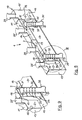
- the manifold 1 has a housing 10, which is welded together from bent steel sheets or profile sections.
- the housing 10 includes a top wall 11, a bottom wall 12, two end faces 13 and 13 'forming walls and a rear wall 15 and a front wall 14.
- Inside the housing 10 is a vertical, seen in its course in the horizontal direction corrugated intermediate wall 17 is arranged.
- a flow chamber 2 and a return chamber 2 ' are separated from each other by the intermediate wall 17, a flow chamber 2 and a return chamber 2 '.
- a switch chamber 3 which is limited here by an inserted into the housing 10 switch chamber 34 with a top-side, horizontal partition 16.
- the swirl chamber 3 is in its left, the first end face 13 of the housing 10 facing region via a first opening 18 in the partition wall 16 upwardly in flow communication with the flow chamber 2.
- the second front end 13 'of the housing 10 facing area is the turnout chamber 3 via a further opening 18 'in the partition wall 16 also upwardly in flow communication with the return chamber 2'.
- two flow connections 20 of two secondary circuits are connected in fluid communication with the flow chamber 2, leading the heat transfer fluid to two heating circuits H1 and H2.
- the flow connection 30 protrudes here in the form of a pipe socket 32 into the interior of the housing 10.
- the pipe socket 32 runs vertically up through the turnout chamber 3 and through an opening 18 in the partition wall 16 passes and opens with its inner end 31 in the flow chamber second
- the opening 18 has a diameter which is greater than the outer diameter of the pipe socket 32, so that the pipe socket 32 around an annular passage remains free.
- the opening 18 forms a flow connection with a predetermined cross section between the switch chamber 3 and the flow chamber 2.
- the pipe socket 32 In its section located in the switch chamber 3, the pipe socket 32 has a plurality of perforations 33 forming a perforation, e.g. Holes.
- the inner end 31 'of the return port 30' of the primary circuit is flush with the bottom wall 12.
- a second, round opening 18 'attached is in the partition 16, a second, round opening 18 'attached.
- the opening 18 ' forms a flow connection with a predetermined cross section between the switch chamber 3 and the return chamber 2'.
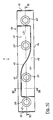
- the flow connection 30 and the return connection 30 'of the primary circuit are here, as the FIGS. 1 and 3 clearly show congruent, ie in alignment with the inner flow port 20 and the inner return port 20 'of the secondary circuits arranged.
- the cooled heat transfer fluid flows through the return ports 20 'from the two heating circuits H1 and H2 in the return chamber 2' back and flows from this From there, the cooled heat transfer fluid flows through the return port 30 'of the primary circuit back to the boiler to be reheated.
- the primary circuit or boiler-side bypass flow takes the form of a primary circuit or boiler circuit-internal source-sink flow, the Sekundärnik- or heating circuit-side flow remains largely untouched, which is when starting the boiler or the boiler or in the supply of a Minimum circulating amount of heat transfer fluid is helpful.
- the annular gap-shaped passage at the first opening 18 and the perforations forming openings 33 in the pipe socket 32 also ensure a very good mixing of warmer and colder heat transfer fluid in the case of a compensation flow or a bypass flow and thus ensure an always homogeneous temperature in the heat transfer fluid, in particular in the flow chamber 2.
- FIGS. 6 to 10 the drawing show the manifold 1 in a second embodiment.
- the return port 30 'of the primary circuit in the form of a pipe socket 32' vertically through the turnout chamber 3 and through the second opening 18 'in the partition wall 16 through to the return chamber 2' runs and with its inner end 31 'in this return chamber 2' opens.
- the switch chamber 3 section of the pipe socket 32 ' has a plurality of perforations forming a perforations 33'.
- the two pipe sockets 32 and 32 ' are identical to each other.
- the flow connections 20 and the return connections 20 'of the secondary circuits are also located in the second example of the manifold 1 on the top of the housing 10 on the top wall 11 and are also arranged here in a line.
- the manifold 1 according to the second embodiment has virtually the same function and the same behavior as the previously described manifold 1 according to the in the FIGS. 1 to 5 illustrated first embodiment, wherein in the second embodiment by the design of the pipe socket 32 'of the return port 30' of the primary circuit and the second opening 18 'the designer of the manifold 1 further influence on the behavior of the manifold 1 are given.
- FIG. 11 shows as a third embodiment of the manifold 1, a design that matches in most parts with the second embodiment of the manifold 1. Different is in the manifold 1 according to FIG. 11 to the second embodiment described above, that now the pipe socket 32 and 32 'of the supply port 30 and the return port 30' of the primary circuit closed at its periphery, so without any openings are executed.
- the pipe socket 32 and 32 ' protrude through the turnout chamber 3 vertically upwards into the flow chamber 2 and return chamber 2'.
- the pipe sockets 32 and 32 ' occur near their upper end 31, 31' in each case by the horizontal partition wall 16, which limits the upper chamber 3, through.
- the two openings 18 and 18 ' are mounted in the horizontal partition 16.
- the diameter of the apertures 18 and 18 ' is greater than the outer diameter of the pipe socket 32 and 32', whereby each annular passage as a flow connection on the one between the switch chamber 3 and the flow chamber 2 and the other between the switch chamber 3 and the return chamber. 2 'is formed.
- the remaining parts of the manifold 1 according to FIG. 11 correspond to those in the FIGS. 5 to 10 described and having the same reference numerals parts. Also the function of the manifold 1 according to FIG. 11 corresponds to the previously described function of the above-described two embodiments, wherein in the manifold 1 according to FIG. 11 for the compensation flow alone, the flow paths through the openings 18 and 18 'are available.
- the pipe manifold 1 has a symmetrical to its perpendicular bisector so that it can be easily installed in a rotated by 180 ° about its perpendicular bisector position, which simplifies the assembly.
- the manifold 1 may also have a larger number of flow connections 20 and return connections 20 'for a correspondingly larger number of secondary circuits, if more than two heating circuits are to be supplied.
- the adaptation to a desired number of secondary circuits or heating circuits can be done simply by appropriate extension of the housing 10 of the manifold 1, whereby a cost-effective modular system is made possible.
Landscapes
- Engineering & Computer Science (AREA)
- General Engineering & Computer Science (AREA)
- Mechanical Engineering (AREA)
- Physics & Mathematics (AREA)
- Thermal Sciences (AREA)
- Chemical & Material Sciences (AREA)
- Combustion & Propulsion (AREA)
- Steam Or Hot-Water Central Heating Systems (AREA)
- Greenhouses (AREA)
- Heat Treatment Of Articles (AREA)
- Rigid Pipes And Flexible Pipes (AREA)
Priority Applications (1)
| Application Number | Priority Date | Filing Date | Title |
|---|---|---|---|
| PL06017730T PL1760406T3 (pl) | 2005-09-05 | 2006-08-25 | Rozdzielacz rurowy do instalacji grzejnej lub chłodniczej |
Applications Claiming Priority (1)
| Application Number | Priority Date | Filing Date | Title |
|---|---|---|---|
| DE202005014029U DE202005014029U1 (de) | 2005-09-05 | 2005-09-05 | Rohrverteiler für eine Heizungs- oder Kühlanlage |
Publications (2)
| Publication Number | Publication Date |
|---|---|
| EP1760406A1 EP1760406A1 (de) | 2007-03-07 |
| EP1760406B1 true EP1760406B1 (de) | 2009-06-10 |
Family
ID=35433697
Family Applications (1)
| Application Number | Title | Priority Date | Filing Date |
|---|---|---|---|
| EP06017730A Active EP1760406B1 (de) | 2005-09-05 | 2006-08-25 | Rohrverteiler für eine Heizungs- oder Kühlanlage |
Country Status (4)
| Country | Link |
|---|---|
| EP (1) | EP1760406B1 (pl) |
| AT (1) | ATE433553T1 (pl) |
| DE (2) | DE202005014029U1 (pl) |
| PL (1) | PL1760406T3 (pl) |
Cited By (1)
| Publication number | Priority date | Publication date | Assignee | Title |
|---|---|---|---|---|
| EP4617570A1 (en) | 2024-03-11 | 2025-09-17 | Cordivari S.r.l. | Hydraulic separator |
Families Citing this family (8)
| Publication number | Priority date | Publication date | Assignee | Title |
|---|---|---|---|---|
| GB0525157D0 (en) * | 2005-12-09 | 2006-01-18 | Ec Power As | Fluid distributor |
| DE102007062362B3 (de) * | 2007-12-22 | 2009-06-18 | Kioto Clear Energy Ag | Vorrichtung zur gerichteten Durchführung mindestens eines Fluids entlang unterschiedlicher Strömungswege |
| DE202009001056U1 (de) | 2009-01-29 | 2010-06-24 | Comfort-Sinusverteiler Gmbh | Heizkreisverteiler |
| DE102009044566A1 (de) * | 2009-11-17 | 2011-05-19 | Domoteck Ltd. | Vorrichtung zum Temperieren eines in einem Heizkreislauf umgewälzten Wärmeübertragungsmediums |
| DE102012203747A1 (de) * | 2012-03-09 | 2013-09-12 | Sinusverteiler Gmbh | Heizkreisverteiler mit integrierter hydraulischer Weiche |
| DE202013105851U1 (de) * | 2013-12-20 | 2014-02-24 | Sinusverteiler Gmbh | Sammler- und Verteilereinheit für das Wärmeträgermedium einer Heizungsanlage mit mehreren Heizkesseln und mehreren Heizkreisen |
| EP3067628B1 (de) * | 2015-03-12 | 2018-07-11 | Grundfos Holding A/S | Hydraulisches ventil |
| RU2680183C1 (ru) * | 2018-03-29 | 2019-02-18 | Манук Лусегенович Чориев | Коллекторный блок |
Family Cites Families (3)
| Publication number | Priority date | Publication date | Assignee | Title |
|---|---|---|---|---|
| DE4234960C1 (de) * | 1992-10-16 | 1994-02-17 | Meinrad Grammer | Rohrverteiler mit hydraulischem Entkoppler |
| WO1997008498A1 (en) * | 1995-08-29 | 1997-03-06 | Monard (Research & Development) Limited | A manifold for connecting circuits of a central heating system |
| DE202005005008U1 (de) * | 2005-03-24 | 2005-07-28 | Comfort Sinusverteiler Gmbh | Rohrverteiler für eine Heizungs- oder Kühlanlage |
-
2005
- 2005-09-05 DE DE202005014029U patent/DE202005014029U1/de not_active Expired - Lifetime
-
2006
- 2006-08-25 DE DE502006003924T patent/DE502006003924D1/de active Active
- 2006-08-25 EP EP06017730A patent/EP1760406B1/de active Active
- 2006-08-25 AT AT06017730T patent/ATE433553T1/de not_active IP Right Cessation
- 2006-08-25 PL PL06017730T patent/PL1760406T3/pl unknown
Cited By (1)
| Publication number | Priority date | Publication date | Assignee | Title |
|---|---|---|---|---|
| EP4617570A1 (en) | 2024-03-11 | 2025-09-17 | Cordivari S.r.l. | Hydraulic separator |
Also Published As
| Publication number | Publication date |
|---|---|
| DE502006003924D1 (de) | 2009-07-23 |
| PL1760406T3 (pl) | 2010-01-29 |
| DE202005014029U1 (de) | 2005-11-17 |
| EP1760406A1 (de) | 2007-03-07 |
| ATE433553T1 (de) | 2009-06-15 |
Similar Documents
| Publication | Publication Date | Title |
|---|---|---|
| EP3119623B1 (de) | Heizkühlmodul | |
| EP1717520B1 (de) | Rohrverteiler für eine Heizungs- oder Kühlanlage | |
| WO2003054466A1 (de) | Wärmeübertrager, insbesondere für ein kraftfahrzeug | |
| DE102008014155A1 (de) | Modulares Batteriesystem mit Kühlsystem | |
| EP0917638A1 (de) | Verteil-/sammel-kasten eines mindestens zweiflutigen verdampfers einer kraftfahrzeugklimaanlage | |
| EP2213948A2 (de) | Heizkreisverteiler | |
| EP1760406B1 (de) | Rohrverteiler für eine Heizungs- oder Kühlanlage | |
| EP2444743A2 (de) | Hydraulische Weiche einer Heiz- oder Kühlanlage | |
| EP2636958B1 (de) | Heizkreisverteiler mit integrierter hydraulischer Weiche | |
| EP2886963B1 (de) | Sammler- und Verteilereinheit für das Wärmeträgermedium einer Heizungsanlage mit mehreren Heizkesseln und mehreren Heizkreisen | |
| EP1760407A1 (de) | Rohrverteiler für eine Heizungs- oder Kühlanlage | |
| DE60213717T2 (de) | Anordnung von Ein- und Auslassstutzen für Verdampfer | |
| DE60201538T2 (de) | Wärmetauscher mit verbesserter leistung, insbesondere verdampfer | |
| DE202009003191U1 (de) | Kaskadeneinheit für eine Heizungsanlage mit zwei oder mehr Heizkesseln | |
| DE3509674A1 (de) | Kondensatheizkessel | |
| DE202010006896U1 (de) | Sammler-Verteiler-Einheit mit hydraulischer Weiche | |
| EP3159614A1 (de) | Rohrverteiler | |
| EP1552238B1 (de) | Wärmeübertrager, insbesondere verdampfer | |
| EP2649378A2 (de) | Hydraulische weiche | |
| DE202004009356U1 (de) | Hydraulische Weiche für eine Heizungsanlage | |
| DE60101082T2 (de) | Plattenwärmetauscher | |
| DE102006031406A1 (de) | Heizkörper, insbesondere Röhrenradiator | |
| AT413149B (de) | Verteilermodul | |
| DE102010061165B3 (de) | Hydraulische Weiche | |
| DE102007035819A1 (de) | Röhrenradiator |
Legal Events
| Date | Code | Title | Description |
|---|---|---|---|
| PUAI | Public reference made under article 153(3) epc to a published international application that has entered the european phase |
Free format text: ORIGINAL CODE: 0009012 |
|
| AK | Designated contracting states |
Kind code of ref document: A1 Designated state(s): AT BE BG CH CY CZ DE DK EE ES FI FR GB GR HU IE IS IT LI LT LU LV MC NL PL PT RO SE SI SK TR |
|
| AX | Request for extension of the european patent |
Extension state: AL BA HR MK YU |
|
| 17P | Request for examination filed |
Effective date: 20070404 |
|
| AKX | Designation fees paid |
Designated state(s): AT BE BG CH CY CZ DE DK EE ES FI FR GB GR HU IE IS IT LI LT LU LV MC NL PL PT RO SE SI SK TR |
|
| AXX | Extension fees paid |
Extension state: BA Payment date: 20070404 Extension state: HR Payment date: 20070404 Extension state: YU Payment date: 20070404 Extension state: AL Payment date: 20070404 Extension state: MK Payment date: 20070404 |
|
| RAX | Requested extension states of the european patent have changed |
Extension state: RS Payment date: 20070404 Extension state: HR Payment date: 20070404 Extension state: MK Payment date: 20070404 Extension state: BA Payment date: 20070404 Extension state: AL Payment date: 20070404 |
|
| GRAP | Despatch of communication of intention to grant a patent |
Free format text: ORIGINAL CODE: EPIDOSNIGR1 |
|
| GRAS | Grant fee paid |
Free format text: ORIGINAL CODE: EPIDOSNIGR3 |
|
| GRAA | (expected) grant |
Free format text: ORIGINAL CODE: 0009210 |
|
| AK | Designated contracting states |
Kind code of ref document: B1 Designated state(s): AT BE BG CH CY CZ DE DK EE ES FI FR GB GR HU IE IS IT LI LT LU LV MC NL PL PT RO SE SI SK TR |
|
| AX | Request for extension of the european patent |
Extension state: AL BA HR MK RS |
|
| REG | Reference to a national code |
Ref country code: GB Ref legal event code: FG4D Free format text: NOT ENGLISH |
|
| REG | Reference to a national code |
Ref country code: CH Ref legal event code: EP |
|
| REG | Reference to a national code |
Ref country code: IE Ref legal event code: FG4D Free format text: LANGUAGE OF EP DOCUMENT: GERMAN |
|
| REF | Corresponds to: |
Ref document number: 502006003924 Country of ref document: DE Date of ref document: 20090723 Kind code of ref document: P |
|
| PG25 | Lapsed in a contracting state [announced via postgrant information from national office to epo] |
Ref country code: FI Free format text: LAPSE BECAUSE OF FAILURE TO SUBMIT A TRANSLATION OF THE DESCRIPTION OR TO PAY THE FEE WITHIN THE PRESCRIBED TIME-LIMIT Effective date: 20090610 Ref country code: LT Free format text: LAPSE BECAUSE OF FAILURE TO SUBMIT A TRANSLATION OF THE DESCRIPTION OR TO PAY THE FEE WITHIN THE PRESCRIBED TIME-LIMIT Effective date: 20090610 |
|
| PG25 | Lapsed in a contracting state [announced via postgrant information from national office to epo] |
Ref country code: LV Free format text: LAPSE BECAUSE OF FAILURE TO SUBMIT A TRANSLATION OF THE DESCRIPTION OR TO PAY THE FEE WITHIN THE PRESCRIBED TIME-LIMIT Effective date: 20090610 Ref country code: SE Free format text: LAPSE BECAUSE OF FAILURE TO SUBMIT A TRANSLATION OF THE DESCRIPTION OR TO PAY THE FEE WITHIN THE PRESCRIBED TIME-LIMIT Effective date: 20090910 Ref country code: SI Free format text: LAPSE BECAUSE OF FAILURE TO SUBMIT A TRANSLATION OF THE DESCRIPTION OR TO PAY THE FEE WITHIN THE PRESCRIBED TIME-LIMIT Effective date: 20090610 |
|
| REG | Reference to a national code |
Ref country code: IE Ref legal event code: FD4D |
|
| PG25 | Lapsed in a contracting state [announced via postgrant information from national office to epo] |
Ref country code: RO Free format text: LAPSE BECAUSE OF FAILURE TO SUBMIT A TRANSLATION OF THE DESCRIPTION OR TO PAY THE FEE WITHIN THE PRESCRIBED TIME-LIMIT Effective date: 20090610 Ref country code: IS Free format text: LAPSE BECAUSE OF FAILURE TO SUBMIT A TRANSLATION OF THE DESCRIPTION OR TO PAY THE FEE WITHIN THE PRESCRIBED TIME-LIMIT Effective date: 20091010 Ref country code: ES Free format text: LAPSE BECAUSE OF FAILURE TO SUBMIT A TRANSLATION OF THE DESCRIPTION OR TO PAY THE FEE WITHIN THE PRESCRIBED TIME-LIMIT Effective date: 20090921 Ref country code: IE Free format text: LAPSE BECAUSE OF FAILURE TO SUBMIT A TRANSLATION OF THE DESCRIPTION OR TO PAY THE FEE WITHIN THE PRESCRIBED TIME-LIMIT Effective date: 20090610 Ref country code: EE Free format text: LAPSE BECAUSE OF FAILURE TO SUBMIT A TRANSLATION OF THE DESCRIPTION OR TO PAY THE FEE WITHIN THE PRESCRIBED TIME-LIMIT Effective date: 20090610 Ref country code: CZ Free format text: LAPSE BECAUSE OF FAILURE TO SUBMIT A TRANSLATION OF THE DESCRIPTION OR TO PAY THE FEE WITHIN THE PRESCRIBED TIME-LIMIT Effective date: 20090610 |
|
| REG | Reference to a national code |
Ref country code: PL Ref legal event code: T3 |
|
| PG25 | Lapsed in a contracting state [announced via postgrant information from national office to epo] |
Ref country code: SK Free format text: LAPSE BECAUSE OF FAILURE TO SUBMIT A TRANSLATION OF THE DESCRIPTION OR TO PAY THE FEE WITHIN THE PRESCRIBED TIME-LIMIT Effective date: 20090610 |
|
| BERE | Be: lapsed |
Owner name: COMFORT-SINUSVERTEILER G.M.B.H. Effective date: 20090831 |
|
| PG25 | Lapsed in a contracting state [announced via postgrant information from national office to epo] |
Ref country code: PT Free format text: LAPSE BECAUSE OF FAILURE TO SUBMIT A TRANSLATION OF THE DESCRIPTION OR TO PAY THE FEE WITHIN THE PRESCRIBED TIME-LIMIT Effective date: 20091010 Ref country code: BG Free format text: LAPSE BECAUSE OF FAILURE TO SUBMIT A TRANSLATION OF THE DESCRIPTION OR TO PAY THE FEE WITHIN THE PRESCRIBED TIME-LIMIT Effective date: 20090910 Ref country code: MC Free format text: LAPSE BECAUSE OF NON-PAYMENT OF DUE FEES Effective date: 20090831 |
|
| PLBE | No opposition filed within time limit |
Free format text: ORIGINAL CODE: 0009261 |
|
| STAA | Information on the status of an ep patent application or granted ep patent |
Free format text: STATUS: NO OPPOSITION FILED WITHIN TIME LIMIT |
|
| PG25 | Lapsed in a contracting state [announced via postgrant information from national office to epo] |
Ref country code: DK Free format text: LAPSE BECAUSE OF FAILURE TO SUBMIT A TRANSLATION OF THE DESCRIPTION OR TO PAY THE FEE WITHIN THE PRESCRIBED TIME-LIMIT Effective date: 20090610 |
|
| 26N | No opposition filed |
Effective date: 20100311 |
|
| PG25 | Lapsed in a contracting state [announced via postgrant information from national office to epo] |
Ref country code: BE Free format text: LAPSE BECAUSE OF NON-PAYMENT OF DUE FEES Effective date: 20090831 |
|
| PG25 | Lapsed in a contracting state [announced via postgrant information from national office to epo] |
Ref country code: GR Free format text: LAPSE BECAUSE OF FAILURE TO SUBMIT A TRANSLATION OF THE DESCRIPTION OR TO PAY THE FEE WITHIN THE PRESCRIBED TIME-LIMIT Effective date: 20090911 |
|
| PG25 | Lapsed in a contracting state [announced via postgrant information from national office to epo] |
Ref country code: AT Free format text: LAPSE BECAUSE OF NON-PAYMENT OF DUE FEES Effective date: 20090825 |
|
| REG | Reference to a national code |
Ref country code: DE Ref legal event code: R409 Ref document number: 502006003924 Country of ref document: DE |
|
| REG | Reference to a national code |
Ref country code: CH Ref legal event code: PL |
|
| PG25 | Lapsed in a contracting state [announced via postgrant information from national office to epo] |
Ref country code: LI Free format text: LAPSE BECAUSE OF NON-PAYMENT OF DUE FEES Effective date: 20100831 Ref country code: LU Free format text: LAPSE BECAUSE OF NON-PAYMENT OF DUE FEES Effective date: 20090825 Ref country code: CH Free format text: LAPSE BECAUSE OF NON-PAYMENT OF DUE FEES Effective date: 20100831 |
|
| PG25 | Lapsed in a contracting state [announced via postgrant information from national office to epo] |
Ref country code: HU Free format text: LAPSE BECAUSE OF FAILURE TO SUBMIT A TRANSLATION OF THE DESCRIPTION OR TO PAY THE FEE WITHIN THE PRESCRIBED TIME-LIMIT Effective date: 20091211 |
|
| PG25 | Lapsed in a contracting state [announced via postgrant information from national office to epo] |
Ref country code: TR Free format text: LAPSE BECAUSE OF FAILURE TO SUBMIT A TRANSLATION OF THE DESCRIPTION OR TO PAY THE FEE WITHIN THE PRESCRIBED TIME-LIMIT Effective date: 20090610 |
|
| PG25 | Lapsed in a contracting state [announced via postgrant information from national office to epo] |
Ref country code: CY Free format text: LAPSE BECAUSE OF FAILURE TO SUBMIT A TRANSLATION OF THE DESCRIPTION OR TO PAY THE FEE WITHIN THE PRESCRIBED TIME-LIMIT Effective date: 20090610 |
|
| REG | Reference to a national code |
Ref country code: DE Ref legal event code: R119 Ref document number: 502006003924 Country of ref document: DE Effective date: 20110228 |
|
| REG | Reference to a national code |
Ref country code: DE Ref legal event code: R409 Ref document number: 502006003924 Country of ref document: DE Ref country code: DE Ref legal event code: R074 Ref document number: 502006003924 Country of ref document: DE |
|
| REG | Reference to a national code |
Ref country code: DE Ref legal event code: R082 Ref document number: 502006003924 Country of ref document: DE Representative=s name: SCHULZE HORN & PARTNER GBR, DE Effective date: 20120531 Ref country code: DE Ref legal event code: R081 Ref document number: 502006003924 Country of ref document: DE Owner name: SINUSVERTEILER GMBH, DE Free format text: FORMER OWNER: COMFORT-SINUSVERTEILER GMBH, 48493 WETTRINGEN, DE Effective date: 20120531 |
|
| PGFP | Annual fee paid to national office [announced via postgrant information from national office to epo] |
Ref country code: NL Payment date: 20140809 Year of fee payment: 9 |
|
| PGFP | Annual fee paid to national office [announced via postgrant information from national office to epo] |
Ref country code: FR Payment date: 20140808 Year of fee payment: 9 Ref country code: PL Payment date: 20140717 Year of fee payment: 9 Ref country code: GB Payment date: 20140820 Year of fee payment: 9 |
|
| PGFP | Annual fee paid to national office [announced via postgrant information from national office to epo] |
Ref country code: IT Payment date: 20140827 Year of fee payment: 9 |
|
| PGFP | Annual fee paid to national office [announced via postgrant information from national office to epo] |
Ref country code: DE Payment date: 20141024 Year of fee payment: 9 |
|
| REG | Reference to a national code |
Ref country code: DE Ref legal event code: R119 Ref document number: 502006003924 Country of ref document: DE |
|
| GBPC | Gb: european patent ceased through non-payment of renewal fee |
Effective date: 20150825 |
|
| PG25 | Lapsed in a contracting state [announced via postgrant information from national office to epo] |
Ref country code: IT Free format text: LAPSE BECAUSE OF NON-PAYMENT OF DUE FEES Effective date: 20150825 |
|
| REG | Reference to a national code |
Ref country code: NL Ref legal event code: MM Effective date: 20150901 |
|
| REG | Reference to a national code |
Ref country code: FR Ref legal event code: ST Effective date: 20160429 |
|
| PG25 | Lapsed in a contracting state [announced via postgrant information from national office to epo] |
Ref country code: NL Free format text: LAPSE BECAUSE OF NON-PAYMENT OF DUE FEES Effective date: 20150901 |
|
| PG25 | Lapsed in a contracting state [announced via postgrant information from national office to epo] |
Ref country code: GB Free format text: LAPSE BECAUSE OF NON-PAYMENT OF DUE FEES Effective date: 20150825 Ref country code: DE Free format text: LAPSE BECAUSE OF NON-PAYMENT OF DUE FEES Effective date: 20160301 |
|
| PG25 | Lapsed in a contracting state [announced via postgrant information from national office to epo] |
Ref country code: FR Free format text: LAPSE BECAUSE OF NON-PAYMENT OF DUE FEES Effective date: 20150831 |
|
| PG25 | Lapsed in a contracting state [announced via postgrant information from national office to epo] |
Ref country code: PL Free format text: LAPSE BECAUSE OF NON-PAYMENT OF DUE FEES Effective date: 20150825 |