EP1760680A2 - Ensemble de panneaux pour l'identification - Google Patents
Ensemble de panneaux pour l'identification Download PDFInfo
- Publication number
- EP1760680A2 EP1760680A2 EP06018060A EP06018060A EP1760680A2 EP 1760680 A2 EP1760680 A2 EP 1760680A2 EP 06018060 A EP06018060 A EP 06018060A EP 06018060 A EP06018060 A EP 06018060A EP 1760680 A2 EP1760680 A2 EP 1760680A2
- Authority
- EP
- European Patent Office
- Prior art keywords
- identification
- plates
- latching
- set according
- label set
- Prior art date
- Legal status (The legal status is an assumption and is not a legal conclusion. Google has not performed a legal analysis and makes no representation as to the accuracy of the status listed.)
- Granted
Links
Images

Classifications
-
- G—PHYSICS
- G09—EDUCATION; CRYPTOGRAPHY; DISPLAY; ADVERTISING; SEALS
- G09F—DISPLAYING; ADVERTISING; SIGNS; LABELS OR NAME-PLATES; SEALS
- G09F3/00—Labels, tag tickets, or similar identification or indication means; Seals; Postage or like stamps
-
- G—PHYSICS
- G09—EDUCATION; CRYPTOGRAPHY; DISPLAY; ADVERTISING; SEALS
- G09F—DISPLAYING; ADVERTISING; SIGNS; LABELS OR NAME-PLATES; SEALS
- G09F7/00—Signs, name or number plates, letters, numerals, or symbols; Panels or boards
-
- H—ELECTRICITY
- H01—ELECTRIC ELEMENTS
- H01R—ELECTRICALLY-CONDUCTIVE CONNECTIONS; STRUCTURAL ASSOCIATIONS OF A PLURALITY OF MUTUALLY-INSULATED ELECTRICAL CONNECTING ELEMENTS; COUPLING DEVICES; CURRENT COLLECTORS
- H01R9/00—Structural associations of a plurality of mutually-insulated electrical connecting elements, e.g. terminal strips or terminal blocks; Terminals or binding posts mounted upon a base or in a case; Bases therefor
- H01R9/22—Bases, e.g. strip, block, panel
- H01R9/24—Terminal blocks
- H01R9/2475—Means facilitating correct wiring, e.g. marking plates, identification tags
-
- H—ELECTRICITY
- H04—ELECTRIC COMMUNICATION TECHNIQUE
- H04Q—SELECTING
- H04Q1/00—Details of selecting apparatus or arrangements
- H04Q1/02—Constructional details
- H04Q1/14—Distribution frames
- H04Q1/148—Identification strips for distribution frames
Definitions
- the invention relates to an identification plate set according to the preamble of claim 1 and an identification plate according to the preamble of claim 18.
- Known identification sign sets have a plurality of identification labels arranged in a row and rigidly connected to one another. They are used to mark electrical or electronic components, for example in a control cabinet. To identify the components they are provided on their identification surface with a label and locked into a receiving geometry in the cabinet.
- the receiving geometry usually consists of two parallel locking rails.
- the rigidly interconnected identification plates are arranged at intervals to each other, which correspond to the distances of the components to be marked. Since these distances may vary, different label sets must be produced with different spacing between the license plates.
- Known identification plates in particular for use as a component of the above-mentioned identification plate sets, have four locking legs each having an approximately square cross-section. As a result, the locking legs for engaging the locking contours in a receiving geometry in a simple manner flexible. However, you can easily cancel.
- the invention is based on the idea that by varying the distances between the individual identification plates by means of deformation of the connecting webs of the identification plate set can be easily adapted to different distances of the components to be marked.
- the identification plate set is stretched or compressed like an accordion.
- the locking legs in a first direction in which the locking contours project have a smaller width than in a second, transverse to the first direction and parallel to the support plate direction, they are slightly flexible in the first direction, but stiffened in the second direction, resulting in increased stability.
- the connecting webs are expediently integrally formed on the carrier plates. Preferably, they are flexible near their ends fixed to the support plates. As a result, the identification plate set is easy to manufacture, especially if it is made in one piece as an injection molded part made of plastic.
- the carrier plates consist of a substantially rigid plastic material
- the connecting webs consist of a material which can be elastically stretched against a restoring force.
- the connecting webs then expediently consist of rubber or an elastomer, which is preferably thermoplastic.
- the connection unit may be materially or non-positively connected to the carrier plates of the identification plates. In particular, it may extend through the carrier plates. However, it is possible that it is pressed non-positively in protruding from the support plate pin. A cohesive connection by sticking to the carrier plates is conceivable.
- each of the identification plates is preferably integrally formed on one of the central carrier.
- the connecting webs are made of a different material than the carrier plates and form a coherent connection unit and the arrangement is produced by means of an injection molding process.
- two methods are advantageous for producing such an arrangement of identification plate sets. According to a first manufacturing method, the connecting units are prefabricated and inserted into an injection mold in a first method step, and in a second method step, the plastic material for forming the identification labels and the central carrier is injected into the injection mold.
- the identification plates and the central carriers are produced in a first injection molding process.
- the space for the connection units is kept free, so that subsequently, after removal of the mandrels, in a second injection molding process, the material for the connection units can be injected.
- each identification plate carries on its attachment side at four attachment points each a detent leg.
- the detent legs and the detent contours of two consecutive in the series label plates are arranged symmetrically with respect to a plane extending in the middle between the license plates symmetry plane. This allows a better and more stable latching connection between the identification plate set and the locking geometry receiving it.
- the attachment points of each identification plate span a regular square.
- the latching contours of facing away in plan view of the mounting side in a circumferential direction of the quadrilateral locking legs facing away from the respective following locking leg, and the locking legs have in a first direction in which the locking contours project, a smaller width than in a second, transverse to the first Direction and parallel to the support plate extending direction.
- Adjacent diagonally opposite latching legs thus have latching contours which project in directions which enclose an angle of 180 ° with each other.
- the identification plate set can then be engaged both on parallel to the row of identification plates extending locking rails as well as on transverse to the row of the identification plates extending locking rails. It is preferred that the locking legs are rectangular in cross section.
- each latching leg having the catch contour is arranged in alignment with one of the side surfaces of the latching leg following a plan view of the attachment side in a circumferential direction of the quadrilateral. This results in a particularly good attachment, as always a locking leg is engaged on a locking rail, while the following in the circumferential direction locking leg rests on the same locking rail.
- the identification plates are then not or only limited to a perpendicular to the support plate axis rotatable.
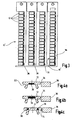
- An identification sign set 10 according to FIG. 1 has a plurality of identification signs 12 arranged in a row, four of which are shown in FIG.
- the consecutive in the series identification plates 12 are connected to each other by means of a connecting web 14, which is integrally formed with each of its two ends 16 on a label 12.
- the entire identification plate set 10, consisting of identification plates 12 and connecting webs 14, is integrally formed as an injection molded part made of plastic.
- the connecting webs 14 are elastically flexible near their ends 16 so that the spacing of the identification plates 12 is varied by deformation of the connecting webs 14 can.
- the series of identification plates 12 can be stretched or compressed accordion-like.
- the identification labels 12 each have a carrier plate 18 which has a flat identification area 20 on one side.
- the latching legs 26 each have a rectangular cross-section, wherein a latching contour 30 projects in each case on a wide side surface 28.
- the latching legs 26 are arranged so that each latching contour 30 faces away from the latching leg 26 which follows the attachment side 22 in a circumferential direction of the regular quadrangle in a circumferential direction.
- the wide side surfaces 28 of the latching legs 26, from which the latching contours 30 protrude, are in alignment with a narrow side surface 32 of the clockwise following latching leg 26.
- each identification plate 12 in the row of the identification plate set 10 is arranged symmetrically to one another. With regard to a center plane extending between two adjacent identification plates 12, each identification plate 12 is the mirror image of the identification plate associated therewith.
- the tag plate sets 10 'according to the second embodiment differ mainly from those of the first embodiment in that their connecting webs 14 are made of a different material than the carrier plates 18. While the carrier plates 18 are substantially rigid Plastic material are made, the connecting webs 14 are made of a thermoplastic elastomer, so that an increase in the distance between two adjacent labels 12 an elastic extension of the connecting connecting web 14 causes against a restoring force.
- the identification plates 12 are also integrally formed via predetermined breaking points having separating webs 34 on the central supports 36. Furthermore, in contrast to the first exemplary embodiment, the connecting webs 14 are not attached individually to the identification labels 12.
- connection unit 38 which extends over the length of the identification plate sets 10 '.
- the respective connection unit 38 can, as shown in Fig. 4a, be glued to the mounting side 22 of the support plates 18.
- a connecting unit 38 extends through the carrier plates 18, while in the embodiment according to FIG. 4c two connecting units 38 arranged parallel to one another extend through the carrier plates 18.
- connection units 38 are prefabricated and placed in an injection mold. Subsequently, the plastic material for forming the identification tags 12 and the central carrier 36 is injected into the injection mold and encloses the connection units 38, as shown in Fig. 4b and Fig. 4c.
- the identification labels 12 and the central supports 36 are first produced as an integral injection molded part in an injection mold. In the injection mold mandrels are inserted, which correspond in shape to the shape of the connection units 38 and which keep the space for the connection units 38. After making the identification labels 12, the mandrels are withdrawn and in their place the thermoplastic elastomer is injected to form the joint units 38.
- the invention relates to a label set 10 with a plurality of arranged in a row and interconnected identification plates 12, each of which a carrier plate 18 having a marking surface 20 for receiving a marking which on a side facing away from the identification surface 20 mounting side 22 locking legs 26 carries with their side surfaces 28 projecting locking contours 30, and wherein the successive in the series identification plates 12 are connected by means of connecting webs 14.
- the connecting webs 14 are deformable for varying the distances between the identification plates 12.
Landscapes
- Engineering & Computer Science (AREA)
- Physics & Mathematics (AREA)
- General Physics & Mathematics (AREA)
- Theoretical Computer Science (AREA)
- Computer Networks & Wireless Communication (AREA)
- Injection Moulding Of Plastics Or The Like (AREA)
- Joining Of Building Structures In Genera (AREA)
- Tents Or Canopies (AREA)
- Moulds For Moulding Plastics Or The Like (AREA)
- Polishing Bodies And Polishing Tools (AREA)
- Holo Graphy (AREA)
- Connection Of Plates (AREA)
- Packaging Of Annular Or Rod-Shaped Articles, Wearing Apparel, Cassettes, Or The Like (AREA)
- Details Of Rigid Or Semi-Rigid Containers (AREA)
Applications Claiming Priority (2)
| Application Number | Priority Date | Filing Date | Title |
|---|---|---|---|
| DE102005041688 | 2005-09-01 | ||
| DE102006003780A DE102006003780A1 (de) | 2005-09-01 | 2006-01-25 | Kennzeichnungsschildersatz |
Publications (3)
| Publication Number | Publication Date |
|---|---|
| EP1760680A2 true EP1760680A2 (fr) | 2007-03-07 |
| EP1760680A3 EP1760680A3 (fr) | 2007-04-25 |
| EP1760680B1 EP1760680B1 (fr) | 2010-07-28 |
Family
ID=37636057
Family Applications (1)
| Application Number | Title | Priority Date | Filing Date |
|---|---|---|---|
| EP06018060A Not-in-force EP1760680B1 (fr) | 2005-09-01 | 2006-08-30 | Panneau pour l'identification |
Country Status (4)
| Country | Link |
|---|---|
| EP (1) | EP1760680B1 (fr) |
| AT (1) | ATE475962T1 (fr) |
| DE (2) | DE102006003780A1 (fr) |
| ES (1) | ES2346779T3 (fr) |
Cited By (2)
| Publication number | Priority date | Publication date | Assignee | Title |
|---|---|---|---|---|
| WO2010108673A1 (fr) * | 2009-03-27 | 2010-09-30 | Phoenix Contact Gmbh & Co. Kg | Plaque signalétique pour composants électriques et procédé de fabrication de cette plaque signalétique |
| CN109392273A (zh) * | 2018-12-05 | 2019-02-26 | 德特威勒(苏州)电缆系统有限公司 | 通信面板 |
Families Citing this family (2)
| Publication number | Priority date | Publication date | Assignee | Title |
|---|---|---|---|---|
| DE202015102586U1 (de) * | 2015-05-20 | 2016-05-24 | Conta-Clip Verbindungstechnik Gmbh | Bezeichnungsschilderstreifen für eine Reihe nebeneinander angeordneter elektrischer Klemmen und Anordnung |
| DE102019105520A1 (de) * | 2019-03-05 | 2020-09-10 | Phoenix Contact Gmbh & Co. Kg | Beschriftungsprofil zur Kennzeichnung von Elektroinstallationen und Verfahren zum Herstellen eines Beschriftungsprofils |
Family Cites Families (12)
| Publication number | Priority date | Publication date | Assignee | Title |
|---|---|---|---|---|
| DE1959596U (de) * | 1967-02-18 | 1967-05-03 | Phoenix Elek Zitaetsgesellscha | Bezeichnungsband fuer reihenklemmen. |
| DE2829620C2 (de) * | 1978-07-06 | 1983-06-30 | Wago-Kontakttechnik Gmbh, 4950 Minden | Bezeichnungsschilderstreifen für die Kennzeichnung insbesondere von Reihenklemmen |
| DE3443170A1 (de) * | 1984-11-27 | 1986-05-28 | Robert Bosch Gmbh, 7000 Stuttgart | Kennzeichnungsschildersatz fuer elektrische installationsmodule, insbesondere stecker und steckverteiler |
| DD256038A1 (de) * | 1986-12-23 | 1988-04-20 | Adw Der Ddr Verwaltungs U Dien | Leiterplatte als traeger- und rueckverdrahtungselement |
| DE8717747U1 (de) * | 1987-07-30 | 1990-01-11 | Murr-Plastik Gmbh, 7155 Oppenweiler | Kennzeichnungsschildersatz |
| DE8806304U1 (de) * | 1988-05-13 | 1988-07-14 | Murrplastik GmbH, 71570 Oppenweiler | Kennzeichnungsschildersatz mit Kennzeichnungsträgern |
| DE9006410U1 (de) * | 1990-06-07 | 1990-08-09 | Zeichentechnik Herbert Rosenbaum, 4300 Essen | Markierungsschilderbogen |
| DE4239434A1 (de) * | 1992-11-24 | 1994-05-26 | Weidmueller Interface | Bezeichnungsschildersatz für elektrische Installationen |
| FR2724250B1 (fr) * | 1994-09-06 | 1996-11-29 | Legrand Sa | Dispositif de reperage, notamment pour conducteur electrique ou bloc de jonction |
| DE9417391U1 (de) * | 1994-10-29 | 1994-12-08 | Weidmüller Interface GmbH & Co, 32760 Detmold | Bezeichnungsschild zur Verrastung in elektrisch/elektronischen Bauelementen |
| DE19913932C1 (de) * | 1999-03-26 | 2000-07-13 | Stn Atlas Elektronik Gmbh | Signalverarbeitungseinheit |
| DE102004024410A1 (de) * | 2004-05-14 | 2005-12-08 | Murrplastik Systemtechnik Gmbh | Verfahren zur Beschriftung eines Kennzeichnungsschildersatzes |
-
2006
- 2006-01-25 DE DE102006003780A patent/DE102006003780A1/de not_active Withdrawn
- 2006-08-30 DE DE502006007519T patent/DE502006007519D1/de active Active
- 2006-08-30 ES ES06018060T patent/ES2346779T3/es active Active
- 2006-08-30 EP EP06018060A patent/EP1760680B1/fr not_active Not-in-force
- 2006-08-30 AT AT06018060T patent/ATE475962T1/de active
Cited By (3)
| Publication number | Priority date | Publication date | Assignee | Title |
|---|---|---|---|---|
| WO2010108673A1 (fr) * | 2009-03-27 | 2010-09-30 | Phoenix Contact Gmbh & Co. Kg | Plaque signalétique pour composants électriques et procédé de fabrication de cette plaque signalétique |
| CN109392273A (zh) * | 2018-12-05 | 2019-02-26 | 德特威勒(苏州)电缆系统有限公司 | 通信面板 |
| CN109392273B (zh) * | 2018-12-05 | 2023-12-01 | 德特威勒(苏州)信息技术科技有限公司 | 通信面板 |
Also Published As
| Publication number | Publication date |
|---|---|
| ES2346779T3 (es) | 2010-10-20 |
| DE102006003780A1 (de) | 2007-03-08 |
| EP1760680B1 (fr) | 2010-07-28 |
| EP1760680A3 (fr) | 2007-04-25 |
| DE502006007519D1 (de) | 2010-09-09 |
| ATE475962T1 (de) | 2010-08-15 |
Similar Documents
| Publication | Publication Date | Title |
|---|---|---|
| DE2437809B2 (de) | Siebboden sowie siebkoerper und rahmen hierfuer | |
| DE102007014755A1 (de) | Vorrichtung zum Halten wenigstens zweier Anschlussleitungen | |
| DE2417284A1 (de) | Rahmen zur aufnahme von elektronischen schaltungen | |
| DE102010060742A1 (de) | Form zur Herstellung von Betonformsteinen | |
| DE102014001161A1 (de) | Haltevorrichtung für Langkörper, insbesondere für Kabel | |
| DE102013215823B4 (de) | Clipsbefestigungsvorrichtung, insbesondere für Kraftfahrzeuge | |
| DE2907656C2 (fr) | ||
| DE102009051392A1 (de) | Verfahren zum Herstellen eines Verbundkörpers aus mindestens einem vorzufertigenden Metallbauteil und mindesten einem Kunststoffbauteil und formschlüssig gefügter Verbundkörper | |
| WO2007065532A1 (fr) | Jeu de plaquettes d'identification | |
| EP1760680B1 (fr) | Panneau pour l'identification | |
| DE202011051267U1 (de) | Vorrichtung zum Stanzen von Zuschnitten aus einem Flächenstück sowie Rinnenprofil | |
| DE2706277C3 (de) | Siebboden | |
| EP3036806B1 (fr) | Conduit de câble et procédé de fabrication d'un conduit de câble s'étendant en trois dimensions | |
| DE102020120936A1 (de) | Vorrichtung zum Schutz eines Körperteils eines Menschen und Verfahren zum Herstellen einer solchen | |
| DE4239434A1 (de) | Bezeichnungsschildersatz für elektrische Installationen | |
| EP0565750A1 (fr) | Elément de fermeture mécanique et liaison obtenue avec cet élément | |
| DE1604743A1 (de) | Befestigungsglied und Verfahren zu dessen Herstellung | |
| DE202009011148U1 (de) | Trägersystem | |
| DE69020322T2 (de) | Tastatur mit festgehaltenen Tasten. | |
| EP1862992B1 (fr) | Plaquettes destinées au marquage du bois, en particulier au marquage de troncs ou de planches | |
| DE69224172T2 (de) | Herstellungsverfahren für eine Markierungentragende Vorrichtung zum Bezeichnen von Leitern | |
| EP0853353A2 (fr) | Utité de ressort de contact realisant une fonction de commutation | |
| DE69606286T2 (de) | Gleiskettenpolster für kettenfahrzeuge | |
| EP0317937A1 (fr) | Système de coffrage | |
| DE2940582A1 (de) | Verfahren, vorrichtung zur durchfuehrung des verfahrens und siebelement hergestellt nach dem verfahren zum beschichten von elementen |
Legal Events
| Date | Code | Title | Description |
|---|---|---|---|
| PUAI | Public reference made under article 153(3) epc to a published international application that has entered the european phase |
Free format text: ORIGINAL CODE: 0009012 |
|
| AK | Designated contracting states |
Kind code of ref document: A2 Designated state(s): AT BE BG CH CY CZ DE DK EE ES FI FR GB GR HU IE IS IT LI LT LU LV MC NL PL PT RO SE SI SK TR |
|
| AX | Request for extension of the european patent |
Extension state: AL BA HR MK YU |
|
| PUAL | Search report despatched |
Free format text: ORIGINAL CODE: 0009013 |
|
| AK | Designated contracting states |
Kind code of ref document: A3 Designated state(s): AT BE BG CH CY CZ DE DK EE ES FI FR GB GR HU IE IS IT LI LT LU LV MC NL PL PT RO SE SI SK TR |
|
| AX | Request for extension of the european patent |
Extension state: AL BA HR MK YU |
|
| 17P | Request for examination filed |
Effective date: 20070630 |
|
| AKX | Designation fees paid |
Designated state(s): AT BE BG CH CY CZ DE DK EE ES FI FR GB GR HU IE IS IT LI LT LU LV MC NL PL PT RO SE SI SK TR |
|
| RTI1 | Title (correction) |
Free format text: IDENTIFICATION PLATE |
|
| GRAP | Despatch of communication of intention to grant a patent |
Free format text: ORIGINAL CODE: EPIDOSNIGR1 |
|
| GRAS | Grant fee paid |
Free format text: ORIGINAL CODE: EPIDOSNIGR3 |
|
| GRAA | (expected) grant |
Free format text: ORIGINAL CODE: 0009210 |
|
| AK | Designated contracting states |
Kind code of ref document: B1 Designated state(s): AT BE BG CH CY CZ DE DK EE ES FI FR GB GR HU IE IS IT LI LT LU LV MC NL PL PT RO SE SI SK TR |
|
| REG | Reference to a national code |
Ref country code: GB Ref legal event code: FG4D Free format text: NOT ENGLISH |
|
| REG | Reference to a national code |
Ref country code: CH Ref legal event code: EP |
|
| REG | Reference to a national code |
Ref country code: IE Ref legal event code: FG4D Free format text: LANGUAGE OF EP DOCUMENT: GERMAN |
|
| REF | Corresponds to: |
Ref document number: 502006007519 Country of ref document: DE Date of ref document: 20100909 Kind code of ref document: P |
|
| REG | Reference to a national code |
Ref country code: ES Ref legal event code: FG2A Ref document number: 2346779 Country of ref document: ES Kind code of ref document: T3 |
|
| REG | Reference to a national code |
Ref country code: NL Ref legal event code: VDEP Effective date: 20100728 |
|
| LTIE | Lt: invalidation of european patent or patent extension |
Effective date: 20100728 |
|
| PG25 | Lapsed in a contracting state [announced via postgrant information from national office to epo] |
Ref country code: NL Free format text: LAPSE BECAUSE OF FAILURE TO SUBMIT A TRANSLATION OF THE DESCRIPTION OR TO PAY THE FEE WITHIN THE PRESCRIBED TIME-LIMIT Effective date: 20100728 Ref country code: FI Free format text: LAPSE BECAUSE OF FAILURE TO SUBMIT A TRANSLATION OF THE DESCRIPTION OR TO PAY THE FEE WITHIN THE PRESCRIBED TIME-LIMIT Effective date: 20100728 Ref country code: LT Free format text: LAPSE BECAUSE OF FAILURE TO SUBMIT A TRANSLATION OF THE DESCRIPTION OR TO PAY THE FEE WITHIN THE PRESCRIBED TIME-LIMIT Effective date: 20100728 |
|
| BERE | Be: lapsed |
Owner name: MURRPLASTIK SYSTEMTECHNIK G.M.B.H. Effective date: 20100831 |
|
| PG25 | Lapsed in a contracting state [announced via postgrant information from national office to epo] |
Ref country code: IS Free format text: LAPSE BECAUSE OF FAILURE TO SUBMIT A TRANSLATION OF THE DESCRIPTION OR TO PAY THE FEE WITHIN THE PRESCRIBED TIME-LIMIT Effective date: 20101128 Ref country code: SI Free format text: LAPSE BECAUSE OF FAILURE TO SUBMIT A TRANSLATION OF THE DESCRIPTION OR TO PAY THE FEE WITHIN THE PRESCRIBED TIME-LIMIT Effective date: 20100728 Ref country code: PT Free format text: LAPSE BECAUSE OF FAILURE TO SUBMIT A TRANSLATION OF THE DESCRIPTION OR TO PAY THE FEE WITHIN THE PRESCRIBED TIME-LIMIT Effective date: 20101129 Ref country code: PL Free format text: LAPSE BECAUSE OF FAILURE TO SUBMIT A TRANSLATION OF THE DESCRIPTION OR TO PAY THE FEE WITHIN THE PRESCRIBED TIME-LIMIT Effective date: 20100728 Ref country code: CY Free format text: LAPSE BECAUSE OF FAILURE TO SUBMIT A TRANSLATION OF THE DESCRIPTION OR TO PAY THE FEE WITHIN THE PRESCRIBED TIME-LIMIT Effective date: 20100728 Ref country code: BG Free format text: LAPSE BECAUSE OF FAILURE TO SUBMIT A TRANSLATION OF THE DESCRIPTION OR TO PAY THE FEE WITHIN THE PRESCRIBED TIME-LIMIT Effective date: 20101028 |
|
| REG | Reference to a national code |
Ref country code: IE Ref legal event code: FD4D |
|
| PG25 | Lapsed in a contracting state [announced via postgrant information from national office to epo] |
Ref country code: LV Free format text: LAPSE BECAUSE OF FAILURE TO SUBMIT A TRANSLATION OF THE DESCRIPTION OR TO PAY THE FEE WITHIN THE PRESCRIBED TIME-LIMIT Effective date: 20100728 Ref country code: GR Free format text: LAPSE BECAUSE OF FAILURE TO SUBMIT A TRANSLATION OF THE DESCRIPTION OR TO PAY THE FEE WITHIN THE PRESCRIBED TIME-LIMIT Effective date: 20101029 Ref country code: SE Free format text: LAPSE BECAUSE OF FAILURE TO SUBMIT A TRANSLATION OF THE DESCRIPTION OR TO PAY THE FEE WITHIN THE PRESCRIBED TIME-LIMIT Effective date: 20100728 Ref country code: MC Free format text: LAPSE BECAUSE OF NON-PAYMENT OF DUE FEES Effective date: 20100831 |
|
| PG25 | Lapsed in a contracting state [announced via postgrant information from national office to epo] |
Ref country code: DK Free format text: LAPSE BECAUSE OF FAILURE TO SUBMIT A TRANSLATION OF THE DESCRIPTION OR TO PAY THE FEE WITHIN THE PRESCRIBED TIME-LIMIT Effective date: 20100728 Ref country code: IE Free format text: LAPSE BECAUSE OF FAILURE TO SUBMIT A TRANSLATION OF THE DESCRIPTION OR TO PAY THE FEE WITHIN THE PRESCRIBED TIME-LIMIT Effective date: 20100728 |
|
| PG25 | Lapsed in a contracting state [announced via postgrant information from national office to epo] |
Ref country code: RO Free format text: LAPSE BECAUSE OF FAILURE TO SUBMIT A TRANSLATION OF THE DESCRIPTION OR TO PAY THE FEE WITHIN THE PRESCRIBED TIME-LIMIT Effective date: 20100728 Ref country code: SK Free format text: LAPSE BECAUSE OF FAILURE TO SUBMIT A TRANSLATION OF THE DESCRIPTION OR TO PAY THE FEE WITHIN THE PRESCRIBED TIME-LIMIT Effective date: 20100728 Ref country code: CZ Free format text: LAPSE BECAUSE OF FAILURE TO SUBMIT A TRANSLATION OF THE DESCRIPTION OR TO PAY THE FEE WITHIN THE PRESCRIBED TIME-LIMIT Effective date: 20100728 Ref country code: EE Free format text: LAPSE BECAUSE OF FAILURE TO SUBMIT A TRANSLATION OF THE DESCRIPTION OR TO PAY THE FEE WITHIN THE PRESCRIBED TIME-LIMIT Effective date: 20100728 |
|
| PLBE | No opposition filed within time limit |
Free format text: ORIGINAL CODE: 0009261 |
|
| STAA | Information on the status of an ep patent application or granted ep patent |
Free format text: STATUS: NO OPPOSITION FILED WITHIN TIME LIMIT |
|
| 26N | No opposition filed |
Effective date: 20110429 |
|
| PG25 | Lapsed in a contracting state [announced via postgrant information from national office to epo] |
Ref country code: BE Free format text: LAPSE BECAUSE OF NON-PAYMENT OF DUE FEES Effective date: 20100831 |
|
| REG | Reference to a national code |
Ref country code: DE Ref legal event code: R097 Ref document number: 502006007519 Country of ref document: DE Effective date: 20110429 |
|
| PG25 | Lapsed in a contracting state [announced via postgrant information from national office to epo] |
Ref country code: LU Free format text: LAPSE BECAUSE OF NON-PAYMENT OF DUE FEES Effective date: 20100830 Ref country code: HU Free format text: LAPSE BECAUSE OF FAILURE TO SUBMIT A TRANSLATION OF THE DESCRIPTION OR TO PAY THE FEE WITHIN THE PRESCRIBED TIME-LIMIT Effective date: 20110129 |
|
| PG25 | Lapsed in a contracting state [announced via postgrant information from national office to epo] |
Ref country code: TR Free format text: LAPSE BECAUSE OF FAILURE TO SUBMIT A TRANSLATION OF THE DESCRIPTION OR TO PAY THE FEE WITHIN THE PRESCRIBED TIME-LIMIT Effective date: 20100728 |
|
| PGFP | Annual fee paid to national office [announced via postgrant information from national office to epo] |
Ref country code: AT Payment date: 20140813 Year of fee payment: 9 |
|
| REG | Reference to a national code |
Ref country code: DE Ref legal event code: R082 Ref document number: 502006007519 Country of ref document: DE Representative=s name: PATENTANWAELTE BREGENZER UND REULE PARTNERSCHA, DE |
|
| PGFP | Annual fee paid to national office [announced via postgrant information from national office to epo] |
Ref country code: GB Payment date: 20150819 Year of fee payment: 10 |
|
| REG | Reference to a national code |
Ref country code: AT Ref legal event code: MM01 Ref document number: 475962 Country of ref document: AT Kind code of ref document: T Effective date: 20150830 |
|
| PG25 | Lapsed in a contracting state [announced via postgrant information from national office to epo] |
Ref country code: AT Free format text: LAPSE BECAUSE OF NON-PAYMENT OF DUE FEES Effective date: 20150830 |
|
| REG | Reference to a national code |
Ref country code: FR Ref legal event code: PLFP Year of fee payment: 11 |
|
| PGFP | Annual fee paid to national office [announced via postgrant information from national office to epo] |
Ref country code: CH Payment date: 20160819 Year of fee payment: 11 |
|
| GBPC | Gb: european patent ceased through non-payment of renewal fee |
Effective date: 20160830 |
|
| PG25 | Lapsed in a contracting state [announced via postgrant information from national office to epo] |
Ref country code: GB Free format text: LAPSE BECAUSE OF NON-PAYMENT OF DUE FEES Effective date: 20160830 |
|
| REG | Reference to a national code |
Ref country code: FR Ref legal event code: PLFP Year of fee payment: 12 |
|
| PGFP | Annual fee paid to national office [announced via postgrant information from national office to epo] |
Ref country code: DE Payment date: 20170522 Year of fee payment: 12 Ref country code: ES Payment date: 20170928 Year of fee payment: 12 Ref country code: IT Payment date: 20170828 Year of fee payment: 12 Ref country code: FR Payment date: 20170822 Year of fee payment: 12 |
|
| REG | Reference to a national code |
Ref country code: CH Ref legal event code: PL |
|
| PG25 | Lapsed in a contracting state [announced via postgrant information from national office to epo] |
Ref country code: LI Free format text: LAPSE BECAUSE OF NON-PAYMENT OF DUE FEES Effective date: 20170831 Ref country code: CH Free format text: LAPSE BECAUSE OF NON-PAYMENT OF DUE FEES Effective date: 20170831 |
|
| REG | Reference to a national code |
Ref country code: DE Ref legal event code: R119 Ref document number: 502006007519 Country of ref document: DE |
|
| PG25 | Lapsed in a contracting state [announced via postgrant information from national office to epo] |
Ref country code: DE Free format text: LAPSE BECAUSE OF NON-PAYMENT OF DUE FEES Effective date: 20190301 Ref country code: IT Free format text: LAPSE BECAUSE OF NON-PAYMENT OF DUE FEES Effective date: 20180830 |
|
| PG25 | Lapsed in a contracting state [announced via postgrant information from national office to epo] |
Ref country code: FR Free format text: LAPSE BECAUSE OF NON-PAYMENT OF DUE FEES Effective date: 20180831 |
|
| REG | Reference to a national code |
Ref country code: ES Ref legal event code: FD2A Effective date: 20190918 |
|
| PG25 | Lapsed in a contracting state [announced via postgrant information from national office to epo] |
Ref country code: ES Free format text: LAPSE BECAUSE OF NON-PAYMENT OF DUE FEES Effective date: 20180831 |