EP1760816A2 - Verfahren und Vorrichtung für das Wassermanagement in einem Direktmethanol-Brennstoffzellensystem mittels Wärmetauscher - Google Patents
Verfahren und Vorrichtung für das Wassermanagement in einem Direktmethanol-Brennstoffzellensystem mittels Wärmetauscher Download PDFInfo
- Publication number
- EP1760816A2 EP1760816A2 EP06119802A EP06119802A EP1760816A2 EP 1760816 A2 EP1760816 A2 EP 1760816A2 EP 06119802 A EP06119802 A EP 06119802A EP 06119802 A EP06119802 A EP 06119802A EP 1760816 A2 EP1760816 A2 EP 1760816A2
- Authority
- EP
- European Patent Office
- Prior art keywords
- fuel
- concentration
- concentration value
- fuel cell
- cell stack
- Prior art date
- Legal status (The legal status is an assumption and is not a legal conclusion. Google has not performed a legal analysis and makes no representation as to the accuracy of the status listed.)
- Withdrawn
Links
Images


Classifications
-
- H—ELECTRICITY
- H01—ELECTRIC ELEMENTS
- H01M—PROCESSES OR MEANS, e.g. BATTERIES, FOR THE DIRECT CONVERSION OF CHEMICAL ENERGY INTO ELECTRICAL ENERGY
- H01M8/00—Fuel cells; Manufacture thereof
- H01M8/04—Auxiliary arrangements, e.g. for control of pressure or for circulation of fluids
- H01M8/04007—Auxiliary arrangements, e.g. for control of pressure or for circulation of fluids related to heat exchange
-
- H—ELECTRICITY
- H01—ELECTRIC ELEMENTS
- H01M—PROCESSES OR MEANS, e.g. BATTERIES, FOR THE DIRECT CONVERSION OF CHEMICAL ENERGY INTO ELECTRICAL ENERGY
- H01M8/00—Fuel cells; Manufacture thereof
- H01M8/04—Auxiliary arrangements, e.g. for control of pressure or for circulation of fluids
- H01M8/04082—Arrangements for control of reactant parameters, e.g. pressure or concentration
- H01M8/04186—Arrangements for control of reactant parameters, e.g. pressure or concentration of liquid-charged or electrolyte-charged reactants
- H01M8/04194—Concentration measuring cells
-
- H—ELECTRICITY
- H01—ELECTRIC ELEMENTS
- H01M—PROCESSES OR MEANS, e.g. BATTERIES, FOR THE DIRECT CONVERSION OF CHEMICAL ENERGY INTO ELECTRICAL ENERGY
- H01M8/00—Fuel cells; Manufacture thereof
- H01M8/04—Auxiliary arrangements, e.g. for control of pressure or for circulation of fluids
- H01M8/04291—Arrangements for managing water in solid electrolyte fuel cell systems
-
- H—ELECTRICITY
- H01—ELECTRIC ELEMENTS
- H01M—PROCESSES OR MEANS, e.g. BATTERIES, FOR THE DIRECT CONVERSION OF CHEMICAL ENERGY INTO ELECTRICAL ENERGY
- H01M8/00—Fuel cells; Manufacture thereof
- H01M8/04—Auxiliary arrangements, e.g. for control of pressure or for circulation of fluids
- H01M8/04298—Processes for controlling fuel cells or fuel cell systems
- H01M8/04313—Processes for controlling fuel cells or fuel cell systems characterised by the detection or assessment of variables; characterised by the detection or assessment of failure or abnormal function
- H01M8/04537—Electric variables
- H01M8/04544—Voltage
- H01M8/04559—Voltage of fuel cell stacks
-
- H—ELECTRICITY
- H01—ELECTRIC ELEMENTS
- H01M—PROCESSES OR MEANS, e.g. BATTERIES, FOR THE DIRECT CONVERSION OF CHEMICAL ENERGY INTO ELECTRICAL ENERGY
- H01M8/00—Fuel cells; Manufacture thereof
- H01M8/04—Auxiliary arrangements, e.g. for control of pressure or for circulation of fluids
- H01M8/04298—Processes for controlling fuel cells or fuel cell systems
- H01M8/04313—Processes for controlling fuel cells or fuel cell systems characterised by the detection or assessment of variables; characterised by the detection or assessment of failure or abnormal function
- H01M8/04537—Electric variables
- H01M8/04574—Current
- H01M8/04589—Current of fuel cell stacks
-
- H—ELECTRICITY
- H01—ELECTRIC ELEMENTS
- H01M—PROCESSES OR MEANS, e.g. BATTERIES, FOR THE DIRECT CONVERSION OF CHEMICAL ENERGY INTO ELECTRICAL ENERGY
- H01M8/00—Fuel cells; Manufacture thereof
- H01M8/04—Auxiliary arrangements, e.g. for control of pressure or for circulation of fluids
- H01M8/04298—Processes for controlling fuel cells or fuel cell systems
- H01M8/04694—Processes for controlling fuel cells or fuel cell systems characterised by variables to be controlled
- H01M8/04791—Concentration; Density
- H01M8/04798—Concentration; Density of fuel cell reactants
-
- H—ELECTRICITY
- H01—ELECTRIC ELEMENTS
- H01M—PROCESSES OR MEANS, e.g. BATTERIES, FOR THE DIRECT CONVERSION OF CHEMICAL ENERGY INTO ELECTRICAL ENERGY
- H01M8/00—Fuel cells; Manufacture thereof
- H01M8/10—Fuel cells with solid electrolytes
- H01M8/1009—Fuel cells with solid electrolytes with one of the reactants being liquid, solid or liquid-charged
- H01M8/1011—Direct alcohol fuel cells [DAFC], e.g. direct methanol fuel cells [DMFC]
-
- H—ELECTRICITY
- H01—ELECTRIC ELEMENTS
- H01M—PROCESSES OR MEANS, e.g. BATTERIES, FOR THE DIRECT CONVERSION OF CHEMICAL ENERGY INTO ELECTRICAL ENERGY
- H01M8/00—Fuel cells; Manufacture thereof
- H01M8/10—Fuel cells with solid electrolytes
- H01M2008/1095—Fuel cells with polymeric electrolytes
-
- H—ELECTRICITY
- H01—ELECTRIC ELEMENTS
- H01M—PROCESSES OR MEANS, e.g. BATTERIES, FOR THE DIRECT CONVERSION OF CHEMICAL ENERGY INTO ELECTRICAL ENERGY
- H01M8/00—Fuel cells; Manufacture thereof
- H01M8/04—Auxiliary arrangements, e.g. for control of pressure or for circulation of fluids
- H01M8/04298—Processes for controlling fuel cells or fuel cell systems
-
- Y—GENERAL TAGGING OF NEW TECHNOLOGICAL DEVELOPMENTS; GENERAL TAGGING OF CROSS-SECTIONAL TECHNOLOGIES SPANNING OVER SEVERAL SECTIONS OF THE IPC; TECHNICAL SUBJECTS COVERED BY FORMER USPC CROSS-REFERENCE ART COLLECTIONS [XRACs] AND DIGESTS
- Y02—TECHNOLOGIES OR APPLICATIONS FOR MITIGATION OR ADAPTATION AGAINST CLIMATE CHANGE
- Y02E—REDUCTION OF GREENHOUSE GAS [GHG] EMISSIONS, RELATED TO ENERGY GENERATION, TRANSMISSION OR DISTRIBUTION
- Y02E60/00—Enabling technologies; Technologies with a potential or indirect contribution to GHG emissions mitigation
- Y02E60/30—Hydrogen technology
- Y02E60/50—Fuel cells
Definitions
- the present invention relates to a method and an apparatus for water management in a direct methanol fuel cell system using a heat exchanger, for supplying fuel having a desired concentration to a fuel cell stack so as to get a stable and continuous operation.
- a fuel cell is a power generation system that generates electric energy by using an electrochemical reaction between oxygen contained in air and hydrogen contained in a hydrocarbonaceous material such as methanol, ethanol, natural gas, etc.
- a fuel cell can be categorized as a phosphate fuel cell, a molten carbonate fuel cell, a solid oxide fuel cell, a polymer electrolyte membrane fuel cell (PEMFC), an alkaline fuel cell, etc., according to the kinds of electrolytes used.
- PEMFC polymer electrolyte membrane fuel cell
- a direct methanol fuel cell is similar to a typical PEMFC because it uses a polymer electrolyte.
- the DMFC differs from the typical PEMFC because it does not need to use a reformer to supply liquid fuel such as methanol to its stack, while the typical PEMFC needs to use the reformer to supply fuel to its stack. Since the DMFC does not need to use the reformer, it can be small in size as compared with the typical PEMFC.
- a DMFC includes a stack, a fuel tank, and a fuel pump.
- a fuel containing hydrogen and an oxidant, such as oxygen, air, etc. are electrochemically reacted to generate electric energy.
- the stack has a structure in which dozens to hundreds of unit cells are stacked adjacent to one of another.
- Each of the unit cells includes a membrane electrode assembly (MEA) and a separator.
- the membrane electrode assembly includes an anode electrode, a cathode electrode, and a polymer electrolyte membrane between the anode electrode and the cathode electrode.
- an operation efficiency of the DMFC can widely vary.
- the molarity of the fuel supplied to the anode electrode is high, the amount of the fuel supplied from the anode electrode to the cathode electrode increases due to a limitation of the polymer electrolyte membrane, and therefore the fuel in the cathode electrode causes a counter electromotive reaction (or force), thereby decreasing an output voltage of the DMFC.
- the DMFC should have an optimum operation efficiency at a certain (or predetermined) molarity of the fuel. Therefore, the molarity of the fuel should be properly (or suitably) adjusted in order to stably and continuously operate the DMFC.
- An embodiment of the present invention provides a method for water management in a direct methanol fuel cell system including a mixer for supplying an anode electrode of a fuel cell stack with a mixed fuel, the mixed fuel including an unreacted fuel and water coming out from the fuel cell stack and a high concentration fuel supplied from a fuel feeder.
- the method includes: measuring an output voltage and/or an output current of the fuel cell stack; extracting a concentration value of the mixed fuel corresponding to the measured output voltage and/or current from a look-up table; comparing the extracted concentration value of the mixed fuel with a reference concentration value; and forcibly cooling a fluid flowing in a pipe for a time period by a heat exchanger coupled to the pipe when the extracted concentration value of the mixed fuel is higher than the reference concentration value, wherein the pipe is for connecting a cathode outlet of the fuel cell stack with the mixer.
- Another embodiment of the present invention provides a method for water management in a direct methanol fuel cell system including a circulator for storing an unreacted fuel and water coming out from a fuel cell stack, and a mixer for providing a mixed fuel by mixing a low concentration fuel from the circulator and a high concentration fuel from a fuel feeder and for supplying the mixed fuel to the fuel cell stack.
- the method includes: sensing a concentration of the low concentration fuel; comparing a concentration value of the low concentration fuel corresponding to the sensed concentration with a reference concentration value; and forcibly cooling fluid flowing in a pipe for a time period by a heat exchanger coupled to the pipe when the extracted concentration value of the low concentration fuel is higher than the reference concentration value, wherein the pipe is for connecting a cathode outlet of the fuel cell stack with the circulator.
- Still another embodiment of the present invention provides an apparatus for water management in a direct methanol fuel cell system including a mixer for supplying an anode electrode of a fuel cell stack with a mixed fuel, the mixed fuel including an unreacted fuel and water coming out from the fuel cell stack and a high concentration fuel supplied from a fuel feeder.
- the apparatus includes: a heat exchanger adjacent to a pipe connecting a cathode outlet of the fuel cell stack with the mixer, and for condensing fluid passing through the pipe; and a controller for measuring an output voltage and/or current of the fuel cell stack, for extracting a concentration value of the mixed fuel corresponding to the measured output voltage and/or current from a previously stored look-up table, and for increasing an amount of fluid condensation by operating the heat exchanger when the extracted concentration value of the mixed fuel is higher than a previously stored reference concentration value.
- FIG. 1 is a block diagram of a direct methanol fuel cell system employing a water management method according to an embodiment of the present invention.
- the direct methanol fuel cell system includes a fuel feeder 110, a fuel cell stack 120, a mixer 130, a pump 140, a controller 150, a power converter 160, and a heat exchanger 170.
- the fuel feeder 110 includes a fuel tank and a pump to supply high concentration fuel stored in the fuel tank to the mixer 130.
- the fuel cell stack 120 has a structure in which dozens to hundreds of unit cells are stacked adjacent to one another.
- Each of the unit cells includes a membrane electrode assembly (MEA) and a separator (or bipolar plate).
- the membrane electrode assembly includes an anode electrode, a cathode electrode, and a polymer electrolyte membrane between the anode electrode and the cathode electrode.
- the fuel cell stack 120 uses a mixed fuel supplied to the anode electrode and an oxidant supplied to the cathode electrode to generate electricity.
- the mixed fuel includes a fuel contain hydrogen, such as methanol, and the oxidant can be air, oxygen, etc.
- an effluent from the cathode electrode of the fuel cell stack 120 is introduced into the mixer 130 through a first pipe 122, and an effluent from the anode electrode of the fuel cell stack 120 is introduced into the mixer 130 through a second pipe 124.
- the mixer 130 stores the mixed fuel in which unreacted fuel and water introduced from the fuel cell stack 120 are mixed with a high concentration fuel supplied from the fuel feeder 110. Further, the mixer 130 can have a mechanism for discharging an undesired gas, such as carbon dioxide, introduced from the fuel cell stack 120, etc.
- the mixed fuel stored in the mixer 130 is supplied to the anode electrode of the fuel cell stack 120 through the pump 140.
- the controller 150 includes a memory adapted to store a program, and a central processing unit connected to the memory and for controlling the fuel cell system based on the program. Further, the controller 150 controls the memory to store reference concentration values for the mixed fuel, in which the reference concentration values are determined according to structures and characteristics of the fuel cell stack 120.
- the controller 150 controls the memory to store concentration values of the mixed fuel corresponding to output voltages and/or output currents of the fuel cell stack 120.
- concentration values of the mixed fuel are provided as a look-up table in which various estimated concentration values are tabulated to correspond to various output voltages and/or various output currents.
- the controller 150 receives an electric signal having a level (or a predetermined level) corresponding to an output voltage and/or an output current of the fuel cell stack 120 from the power converter 160.
- the received electric signal is converted by the controller 150 into a fuel concentration value (or a predetermined concentration value) corresponding to the output voltage and/or the output current, and the concentration value is used in controlling the heat exchanger 170.
- the power converter 160 supplies an electric power to the controller 150, the pump 140, or an external load, while the fuel cell stack 120 operates in a normal manner.
- the power converter 160 transmits the output voltage and/or the output current of the fuel cell stack 120 to the controller 150.
- the heat exchanger 170 is provided adjacent to the first pipe 122 connecting the fuel cell stack 120 with the mixer 130.
- the heat exchanger 170 is controlled to be turned on or to be turned off based on a control signal from the controller 150.
- the heat exchanger 170 is implemented by a fan used in controlling a system temperature. The fan can blow air toward the first pipe 122.
- the first pipe 122 is partially or wholly shaped as a spiral, a coil, etc.
- at least a part of the first pipe 122, which is opposite to a propeller of the fan of the heat exchanger 170, is shaped as a spiral, a coil, etc.
- FIG. 2 is a flowchart of the water management method of the direct methanol fuel cell system of Figure 1.
- the controller 150 senses the output voltage and/or the output current of the fuel cell stack 120, and extracts a concentration value of the mixed fuel corresponding to the sensed signal from a previously stored look-up table.
- the look-up table previously stores various estimated concentration values of the mixed fuel corresponding to various output voltages and/or various output currents of the fuel cell stack 120. Further, the look-up table can be tabulated according to the characteristics of the fuel cell stack 120.
- the cooling time period is determined depending on a difference between the extracted concentration value of the mixed fuel and the reference concentration value. For example, when a difference between the extracted concentration value of the mixed fuel and the reference concentration value is large, the fan is turned on for a relative long time period proportional to the difference between the extracted concentration value of the mixed fuel and the reference concentration value.
- the heat exchanger 170 does not operate and the current operation is stopped. Since the heat exchanger 170 does not operate, external air is not supplied from the heat exchanger 170 to the pipe 122.
- a blocking mechanism or the like may be provided to block or prevent the external air from being supplied from the heat exchanger 170 to the pipe 122, so that the fluid passing through (or within) the pipe 122 between the cathode outlet of the fuel cell stack 120 and the mixer 130 is not substantially affected by the heat exchanger 170.
- the fuel feeder 110 can be controlled to increase the amount of the high concentration fuel supplied from the fuel feeder 110 for a time period (or a predetermined time period).
- the current operation can be stopped without performing an additional process (such as without increasing the amount of the high concentration fuel supplied from the fuel feeder 110).
- the condensation of water vapor passing through the first pipe is increased, and the amount of water introduced into the mixer is increased as much as the increased condensation, so that the concentration of the fuel in the mixer is correspondingly lowered.
- the mixed fuel having a desired concentration is supplied to the fuel cell stack 120.
- the heat exchanger 170 is used for effectively managing the water produced in the fuel cell stack 120, so that the fuel having the desired concentration can be supplied to the fuel cell stack 120.
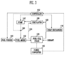
- FIG 3 is a block diagram of a direct methanol fuel cell system employing a water management method according to another embodiment of the present invention.
- the direct methanol fuel cell system includes a fuel feeder 110, a fuel cell stack 120, a fuel mixer 132, a pump 142, a controller 152, a power converter 160, a heat exchanger 170, a circulator 180, and a concentration sensor 190.
- the fuel cell stack 120 includes an anode electrode and a cathode electrode and generates electric energy by electrochemical reaction between a fuel containing hydrogen supplied to the anode electrode and an oxidant supplied to the cathode electrode.
- an effluent from the cathode electrode of the fuel cell stack 120 is introduced into the circulator 180 through a first pipe 122, and an effluent from the anode electrode of the fuel cell stack 120 is introduced into the circulator 180 through a second pipe 124.
- the unreacted fuel and water introduced into the circulator 180 are supplied as a low concentration fuel to the fuel mixer 132 through the pump 142.
- the low concentration fuel supplied to the fuel mixer 132 is mixed with a high concentration fuel supplied from the fuel feeder 110, and then supplied back to the anode electrode of the fuel cell stack 120.
- the circulator 180 stores the unreacted fuel from an anode outlet of the fuel cell stack 120 and discharges a reaction product, such as carbon dioxide or the like. Further, the circulator 180 stores water from a cathode outlet of the fuel cell stack 120 and discharges an unwanted gas, such as nitrogen, oxygen, etc. Also, the circulator 180 employs the pump 142 to supply the low concentration fuel obtained by mixing the unreacted fuel with water to the fuel mixer 132.
- the circulator 180 includes a lower part in which the effluent from the anode electrode is introduced, an upper part in which the effluent from the cathode electrode is introduced, and a selective permeable membrane to allow gas and liquid to permeate the upper part and the lower part, respectively.
- the fuel mixer 132 includes a tank or the like, in which the high concentration fuel from the fuel feeder 110 and the low concentration fuel from the circulator 180 are mixed and stored.
- the fuel mixer 132 has a structure to smoothly (or uniformly) mix the high concentration fuel and the low concentration fuel together (without lumps).
- the fuel mixer 132 has a mixing tank structure in which the high concentration fuel and the low concentration fuel are mixed while passing through a resin or a filter.
- the controller 152 includes a memory adapted to store a program, and a central processing unit connected to the memory and for controlling the fuel cell system based on the program. Further, the controller 152 controls the memory to store reference concentration values for the mixed fuel, in which the reference concentration values are determined according to structures and characteristics of the fuel cell stack 120. Also, the controller 152 controls the memory to store estimated concentration values of the low concentration fuel corresponding to output voltages and/or output currents of the fuel cell stack 120. For example, the stored concentration values of the low concentration fuel are provided as a look-up table in which estimated various concentration values are tabulated corresponding to various output voltages and/or various output currents of the fuel cell stack.
- the controller 152 receives an electric signal having a level (or a predetermined level) corresponding to the concentration value of the low concentration fuel from the concentration sensor 190. Also, the controller 152 controls the heat exchanger 170 to be turned on or off based on the concentration value of the low concentration fuel corresponding to the received electric signal. As described above, the controller 152 measures the output voltage and/or the output current of the fuel cell stack 120 by the power converter 160, and controls the heat exchanger 170 to be turned on or off according to the concentration values of the low concentration fuel corresponding to the measured signal. Further, the controller 152 controls the pump 142 and/or the fuel feeder 110.
- the heat exchanger 170 is provided adjacent to the first pipe 122 connecting the fuel cell stack 120 with the circulator 180, and is used in forcibly cooling the fluid passing through (or within) the first pipe 122.
- the heat exchanger 170 is controlled by the controller 152 to be turned on or off according to the sensed concentration of the fuel, thereby setting the concentration of the fuel supplied to the anode electrode of the fuel cell stack 120 into a desired concentration.
- the heat exchanger 170 can be implemented by a fan, but the present invention is not thereby limited.
- the heat exchanger 170 can be implemented by surrounding the first pipe 122 with another pipe through which heat exchanging fluid flows.
- the concentration sensor 190 senses the concentration of the low concentration fuel supplied from the circulator 180 to the fuel mixer 132. In other words, the concentration sensor 190 senses the concentration of the low concentration fuel, and transmits an electric signal corresponding to the sensed concentration to the controller 152. Here, the electric signal can pass through a device, such as an amplifier or the like, before being transmitted to the controller 152.
- the concentration sensor 190 is placed in a fuel transferring pipe connecting the circulator 180 and the fuel mixer 132. Alternatively, the concentration sensor 190 may be internally provided in the circulator 180.
- the concentration sensor 190 can be implemented by a sensor using an ionic conduction polymer resin, a complex resin, etc., in which the volume is varied according to the concentration of the fuel, such as methanol.
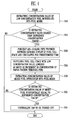
- FIG 4 is a flowchart of the water management method of the direct methanol fuel cell system of Figure 3.
- the controller 152 receives a first electric signal regarding the concentration of the low concentration fuel from the concentration sensor 190 that senses the concentration of the low concentration fuel stored in the circulator 180 and supplied to the fuel mixer 130, and extracts a concentration value of the low concentration fuel corresponding to the received first electric signal from a previously stored first look-up table.
- the first look-up table previously stores the concentrations sensed by the concentration sensor 190 and the levels of electric signals corresponding to the concentrations of the fuel.
- the controller 152 determines whether or not the extracted concentration value of the low concentration fuel is higher than the reference concentration value of the low concentration fuel while referring to the reference concentration values of the low concentration fuel stored in the memory.
- the fluid passing through (or within) the first pipe 122 provided between a cathode outlet of the fuel cell stack 120 and the circulator 180 is forcibly cooled for a on-time period (or a predetermined time period), at operation S26.
- the on-time period of the heat exchanger 170 is determined depending on a difference between the extracted concentration value of the low concentration fuel and the reference concentration value. For example, the heat exchanger 170 is turned on for a relatively long time when the extracted concentration value of the low concentration fuel is different from the reference concentration value by a relatively large amount.
- the pump 142 supplying the fuel mixer 132 with the low concentration fuel is controlled to decrease the amount of the low concentration fuel supplied from the circulator 180 to the fuel mixer 132 for a time period (or a predetermined time period).
- the current operation can be stopped without performing an additional process (such as without decreasing the amount of the low concentration fuel supplied).
- the condensation of water vapor passing through the first pipe is increased, and the amount of water introduced into the mixer is increased as much as the increased condensation. Therefore, the concentration of the low concentration fuel in the circulator is lowered, so that the low concentration fuel having the desired low concentration can be supplied by the pump 142 to the fuel mixer 132, at operation S28.
- the concentration of the mixed fuel introduced into the fuel cell stack 120 is extracted.
- the concentration value of the mixed fuel corresponding to the output voltage and/or the output current of the fuel cell stack 120 is extracted from a second look-up table previously stored in the controller 152.
- the second look-up table previously stores the concentration values of the mixed fuel corresponding to the output voltages and/or the output currents of the fuel cell stack.
- the concentration of the mixed fuel can be extracted by using a concentration sensor similar to the sensor 190 for sensing the concentration of the low concentration fuel.
- FIG. 5 is a block diagram of a controller 500 employed in a water management apparatus of a direct methanol fuel cell system according to an embodiment of the present invention.
- the controller 200 includes a memory system 207 for storing a program that controls various elements of a fuel cell system, in particular, a direct methanol fuel cell system, in order to manage water of the direct methanol fuel cell system; and a processor 201 connected to the memory system 207 and executing the program.
- the processor 201 includes an arithmetic logic unit (ALU) 202 to perform one or more calculations, a register to temporarily store data and command(s), and a controller 204 to control operation(s) of the fuel cell system.
- ALU arithmetic logic unit
- the processor 201 includes one or more of processors having various architectures, such as Alpha of Digital; MIPS technology; MIPS of NEC, IDT, Siemens, etc.; x86 of Intel & Cyrix, AMD and Nexgen; and Power PC of IBM and Motorola.
- the processor 201 receives electric power from the fuel cell stack and/or a separate power supply 214; measures the output voltage and/or current 213 of the fuel cell stack, and receives an electric signal about the fuel concentration from the concentration sensor 211 via an amplifier 212.
- the received signal is transmitted to the processor 201 through an input terminal 205 (e.g., analog-digital converter).
- the processor 201 controls a first pump 215, a second pump 216 and a third pump 217 which are used in the fuel feeder, the oxidant feeder, etc. Also, the processor 201 controls a driver to drive the respective pumps 215, 216, and 217, or directly controls the pumps 215, 216, and 217 through a frequency or the like. Also, the processor 201 controls a heat exchanger 218 based on the output voltage and/or current of the fuel cell stack or based on the fuel concentration sensed by a concentration sensor 211.
- the memory system 207 includes a high speed main memory, such as a random access memory (RAM), a read only memory (ROM), etc.; an auxiliary memory for term storage, such as a floppy disk, a hard disk, a magnetic tape, a compact disk (CD)-read only memory (ROM), a flash memory, etc.; and a device for storing data using electric storage media, magnetic media, optic media, or the like.
- the main memory may include a video memory that displays an image through a display device.
- the memory system 207 includes a look-up table 208 for storing the output voltages and/or currents of the fuel cell stack and fuel concentration values corresponding thereto; and a look-up table 209 for storing the electric signals input from the concentration sensor 211 and the concentration values of the low concentration fuel corresponding thereto.
- the look-up tables 208 and 209 are referred in controlling the operations of the heat exchanger 218.
- the memory system 207 stores the reference concentration values of the mixed fuel and the reference concentration values of the low concentration fuel.
- the reference concentration values are previously set according to the characteristics of the fuel cell stack in order to optimize the operation efficiency of the fuel cell stack.
- a water management apparatus controls a heat exchanger based on an output voltage and/or an output current of a fuel cell stack and/or based on a concentration of a low concentration fuel sensed by a concentration sensor, so that a mixed fuel having a desired concentration is supplied to the fuel cell stack, thereby operating the fuel cell stack stably and continuously (for a long time).
- a heat exchanger provided adjacent to a pipe connected to a cathode outlet of a fuel cell stack is used to control an amount of fluid condensation (or a condensing amount of a fluid) coming out from a cathode electrode of the fuel cell stack, so that water is efficiently managed and the direct methanol fuel cell system is stably and continuously operated.
- the heat exchanger (or another heat exchanger) may be provided adjacent to an anode outlet as well as the cathode outlet of the fuel cell stack, so that the unreacted fuel coming out from the anode electrode of the fuel cell stack can be effectively recovered.
- a heat exchanger is used in efficiently controlling water coming out from a cathode electrode of the fuel cell stack, so that a fuel having a desired concentration is supplied to the fuel cell stack, thereby enhancing an operation efficiency of the fuel cell system, and to stably and continuously operate the direct methanol fuel cell system.
Landscapes
- Life Sciences & Earth Sciences (AREA)
- Engineering & Computer Science (AREA)
- Manufacturing & Machinery (AREA)
- Sustainable Development (AREA)
- Sustainable Energy (AREA)
- Chemical & Material Sciences (AREA)
- Chemical Kinetics & Catalysis (AREA)
- Electrochemistry (AREA)
- General Chemical & Material Sciences (AREA)
- Fuel Cell (AREA)
Applications Claiming Priority (2)
| Application Number | Priority Date | Filing Date | Title |
|---|---|---|---|
| KR1020050080989A KR100639011B1 (ko) | 2005-08-31 | 2005-08-31 | 열교환기를 이용한 연료전지 제어 시스템 |
| KR1020050090736A KR20070035855A (ko) | 2005-09-28 | 2005-09-28 | 직접 메탄올 연료전지시스템의 열교환기를 이용한 물관리방법 |
Publications (2)
| Publication Number | Publication Date |
|---|---|
| EP1760816A2 true EP1760816A2 (de) | 2007-03-07 |
| EP1760816A3 EP1760816A3 (de) | 2010-05-05 |
Family
ID=37497048
Family Applications (1)
| Application Number | Title | Priority Date | Filing Date |
|---|---|---|---|
| EP06119802A Withdrawn EP1760816A3 (de) | 2005-08-31 | 2006-08-30 | Verfahren und Vorrichtung für das Wassermanagement in einem Direktmethanol-Brennstoffzellensystem mittels Wärmetauscher |
Country Status (3)
| Country | Link |
|---|---|
| US (1) | US20070048560A1 (de) |
| EP (1) | EP1760816A3 (de) |
| JP (1) | JP2007066910A (de) |
Families Citing this family (1)
| Publication number | Priority date | Publication date | Assignee | Title |
|---|---|---|---|---|
| US20110244351A1 (en) * | 2010-04-01 | 2011-10-06 | Jung-Kurn Park | Operating method of fuel cell system |
Family Cites Families (13)
| Publication number | Priority date | Publication date | Assignee | Title |
|---|---|---|---|---|
| JPS6366860A (ja) * | 1986-09-09 | 1988-03-25 | Hitachi Ltd | メタノ−ル燃料電池 |
| US5773162A (en) * | 1993-10-12 | 1998-06-30 | California Institute Of Technology | Direct methanol feed fuel cell and system |
| US5573866A (en) * | 1995-05-08 | 1996-11-12 | International Fuel Cells Corp. | Direct methanol oxidation polymer electrolyte membrane power system |
| CA2334530A1 (en) * | 2001-02-06 | 2002-08-06 | General Motors Corporation | A direct methanol fuel cell system with a device for the separation of the methanol and water mixture |
| US6686081B2 (en) * | 2001-05-15 | 2004-02-03 | Mti Microfuel Cells, Inc. | Methods and apparatuses for a pressure driven fuel cell system |
| DE50208651D1 (de) * | 2002-07-01 | 2006-12-21 | Sfc Smart Fuel Cell Ag | Regelung des Wasserhaushalts in Brennstoffzellensystemen |
| DE10393382T5 (de) * | 2002-09-30 | 2005-08-25 | Gs Yuasa Corp. | Flüssigbrennstoffdirektzufuhr-Brennstoffzellensystem; Verfahren zur Betriebssteuerung und Betriebssteuervorrichtung |
| JP4529373B2 (ja) * | 2003-04-28 | 2010-08-25 | ソニー株式会社 | 燃料電池および燃料電池の運転方法 |
| US7060382B2 (en) * | 2003-05-15 | 2006-06-13 | Fuelcell Energy, Inc. | Fuel cell system with recycle of anode exhaust gas |
| US7452625B2 (en) * | 2003-06-20 | 2008-11-18 | Oorja Protonics | Water management in a direct methanol fuel cell system |
| JP4697380B2 (ja) * | 2003-07-07 | 2011-06-08 | ソニー株式会社 | 燃料電池装置及び燃料電池の燃料供給方法 |
| JP2005098709A (ja) * | 2003-09-22 | 2005-04-14 | Matsushita Electric Ind Co Ltd | 液体濃度センサ、燃料電池用液体濃度センサ、ならびに該液体濃度センサを用いた燃料電池システム及び電子機器 |
| JP2005222823A (ja) * | 2004-02-06 | 2005-08-18 | Matsushita Electric Ind Co Ltd | 燃料電池発電方法 |
-
2006
- 2006-08-30 EP EP06119802A patent/EP1760816A3/de not_active Withdrawn
- 2006-08-31 JP JP2006236075A patent/JP2007066910A/ja active Pending
- 2006-08-31 US US11/515,293 patent/US20070048560A1/en not_active Abandoned
Also Published As
| Publication number | Publication date |
|---|---|
| EP1760816A3 (de) | 2010-05-05 |
| JP2007066910A (ja) | 2007-03-15 |
| US20070048560A1 (en) | 2007-03-01 |
Similar Documents
| Publication | Publication Date | Title |
|---|---|---|
| EP1770814A2 (de) | Regelvorrichtung und entsprechendes Steuerverfahren für Brennstoffzellensystem | |
| US20080026264A1 (en) | Fuel cell system and operation control method therefore | |
| US20080075988A1 (en) | Fuel cell system and method of controlling a fuel cell system | |
| EP2056385B1 (de) | Verfahren und Vorrichtung zum Steuern der Brennstoffkonzentration in einer flüssigen Brennstoffzelle | |
| US20070264548A1 (en) | Fuel cell system and control method thereof | |
| JP4697380B2 (ja) | 燃料電池装置及び燃料電池の燃料供給方法 | |
| US20060222915A1 (en) | Direct-methanol fuel cell system and method for controlling the same | |
| US8343674B2 (en) | Fuel cell system and control method of the same | |
| US6504339B2 (en) | Technique and apparatus to control the charging of a battery using a fuel cell | |
| US20040062962A1 (en) | Cell unit having fuel cell, electronic apparatus having fuel cell, and controlling method of operation of fuel cell in multi-step manner for efficient operation | |
| JP5367003B2 (ja) | 燃料電池システムの駆動方法およびシステム | |
| US20060083966A1 (en) | Fuel cell unit and method for controlling liquid volume | |
| US8241799B2 (en) | Methods of operating fuel cell power generators, and fuel cell power generators | |
| US20080026272A1 (en) | Fuel supply system for fuel cell and fuel cell system using the same | |
| US20080102333A1 (en) | Fuel cell unit | |
| KR20090043967A (ko) | 연료전지 시스템 | |
| US8088521B2 (en) | Fuel cell system for computing fuel level | |
| EP1760816A2 (de) | Verfahren und Vorrichtung für das Wassermanagement in einem Direktmethanol-Brennstoffzellensystem mittels Wärmetauscher | |
| KR20060108341A (ko) | 연료전지 운전중지 방법 및 이를 이용한 연료전지 장치 | |
| KR20070039359A (ko) | 연료 전지 제어 방법 및 연료 전지 시스템 | |
| US20110273131A1 (en) | Fuel cell system and driving method thereof | |
| KR100639011B1 (ko) | 열교환기를 이용한 연료전지 제어 시스템 | |
| US20090081503A1 (en) | Fuel cell system and driving method thereof | |
| KR100786481B1 (ko) | 연료전지 시스템 운전제어 방법 및 장치와 이를 채용한직접 메탄올형 연료전지 시스템 | |
| KR20070035855A (ko) | 직접 메탄올 연료전지시스템의 열교환기를 이용한 물관리방법 |
Legal Events
| Date | Code | Title | Description |
|---|---|---|---|
| PUAI | Public reference made under article 153(3) epc to a published international application that has entered the european phase |
Free format text: ORIGINAL CODE: 0009012 |
|
| 17P | Request for examination filed |
Effective date: 20060903 |
|
| AK | Designated contracting states |
Kind code of ref document: A2 Designated state(s): AT BE BG CH CY CZ DE DK EE ES FI FR GB GR HU IE IS IT LI LT LU LV MC NL PL PT RO SE SI SK TR |
|
| AX | Request for extension of the european patent |
Extension state: AL BA HR MK YU |
|
| RAP1 | Party data changed (applicant data changed or rights of an application transferred) |
Owner name: SAMSUNG SDI CO., LTD. |
|
| PUAL | Search report despatched |
Free format text: ORIGINAL CODE: 0009013 |
|
| AK | Designated contracting states |
Kind code of ref document: A3 Designated state(s): AT BE BG CH CY CZ DE DK EE ES FI FR GB GR HU IE IS IT LI LT LU LV MC NL PL PT RO SE SI SK TR |
|
| AX | Request for extension of the european patent |
Extension state: AL BA HR MK RS |
|
| AKX | Designation fees paid |
Designated state(s): DE FR GB |
|
| STAA | Information on the status of an ep patent application or granted ep patent |
Free format text: STATUS: THE APPLICATION IS DEEMED TO BE WITHDRAWN |
|
| 18D | Application deemed to be withdrawn |
Effective date: 20101106 |