EP1760862A1 - Elektrisches Lebensmittelverarbeitungsgerät mit einer verbesserten Kühlungsvorrichtung - Google Patents
Elektrisches Lebensmittelverarbeitungsgerät mit einer verbesserten Kühlungsvorrichtung Download PDFInfo
- Publication number
- EP1760862A1 EP1760862A1 EP06291359A EP06291359A EP1760862A1 EP 1760862 A1 EP1760862 A1 EP 1760862A1 EP 06291359 A EP06291359 A EP 06291359A EP 06291359 A EP06291359 A EP 06291359A EP 1760862 A1 EP1760862 A1 EP 1760862A1
- Authority
- EP
- European Patent Office
- Prior art keywords
- air
- stator
- motor
- shaft
- fan
- Prior art date
- Legal status (The legal status is an assumption and is not a legal conclusion. Google has not performed a legal analysis and makes no representation as to the accuracy of the status listed.)
- Withdrawn
Links
- 238000009423 ventilation Methods 0.000 title claims abstract description 22
- 235000013305 food Nutrition 0.000 title claims description 5
- 238000011144 upstream manufacturing Methods 0.000 claims abstract description 6
- 238000001816 cooling Methods 0.000 claims description 7
- 238000004804 winding Methods 0.000 description 7
- 235000021183 entrée Nutrition 0.000 description 4
- 230000005355 Hall effect Effects 0.000 description 2
- XEEYBQQBJWHFJM-UHFFFAOYSA-N Iron Chemical compound [Fe] XEEYBQQBJWHFJM-UHFFFAOYSA-N 0.000 description 2
- 238000010438 heat treatment Methods 0.000 description 2
- 238000013021 overheating Methods 0.000 description 2
- 230000000295 complement effect Effects 0.000 description 1
- 230000008878 coupling Effects 0.000 description 1
- 238000010168 coupling process Methods 0.000 description 1
- 238000005859 coupling reaction Methods 0.000 description 1
- 238000010586 diagram Methods 0.000 description 1
- 229910052742 iron Inorganic materials 0.000 description 1
- 239000000463 material Substances 0.000 description 1
- 238000005259 measurement Methods 0.000 description 1
- 230000002093 peripheral effect Effects 0.000 description 1
- 238000002360 preparation method Methods 0.000 description 1
- 230000000135 prohibitive effect Effects 0.000 description 1
- 230000001960 triggered effect Effects 0.000 description 1
Images

Classifications
-
- H—ELECTRICITY
- H02—GENERATION; CONVERSION OR DISTRIBUTION OF ELECTRIC POWER
- H02K—DYNAMO-ELECTRIC MACHINES
- H02K9/00—Arrangements for cooling or ventilating
- H02K9/02—Arrangements for cooling or ventilating by ambient air flowing through the machine
- H02K9/04—Arrangements for cooling or ventilating by ambient air flowing through the machine having means for generating a flow of cooling medium
- H02K9/06—Arrangements for cooling or ventilating by ambient air flowing through the machine having means for generating a flow of cooling medium with fans or impellers driven by the machine shaft
-
- A—HUMAN NECESSITIES
- A47—FURNITURE; DOMESTIC ARTICLES OR APPLIANCES; COFFEE MILLS; SPICE MILLS; SUCTION CLEANERS IN GENERAL
- A47J—KITCHEN EQUIPMENT; COFFEE MILLS; SPICE MILLS; APPARATUS FOR MAKING BEVERAGES
- A47J43/00—Implements for preparing or holding food, not provided for in other groups of this subclass
- A47J43/04—Machines for domestic use not covered elsewhere, e.g. for grinding, mixing, stirring, kneading, emulsifying, whipping or beating foodstuffs, e.g. power-driven
- A47J43/044—Machines for domestic use not covered elsewhere, e.g. for grinding, mixing, stirring, kneading, emulsifying, whipping or beating foodstuffs, e.g. power-driven with tools driven from the top side
- A47J2043/04409—Apparatus of hand held type
- A47J2043/04427—Apparatus of hand held type with housing extending vertically in line with the tool axis
-
- A—HUMAN NECESSITIES
- A47—FURNITURE; DOMESTIC ARTICLES OR APPLIANCES; COFFEE MILLS; SPICE MILLS; SUCTION CLEANERS IN GENERAL
- A47J—KITCHEN EQUIPMENT; COFFEE MILLS; SPICE MILLS; APPARATUS FOR MAKING BEVERAGES
- A47J43/00—Implements for preparing or holding food, not provided for in other groups of this subclass
- A47J43/04—Machines for domestic use not covered elsewhere, e.g. for grinding, mixing, stirring, kneading, emulsifying, whipping or beating foodstuffs, e.g. power-driven
- A47J43/07—Parts or details, e.g. mixing tools, whipping tools
- A47J43/08—Driving mechanisms
-
- H—ELECTRICITY
- H02—GENERATION; CONVERSION OR DISTRIBUTION OF ELECTRIC POWER
- H02K—DYNAMO-ELECTRIC MACHINES
- H02K23/00—DC commutator motors or generators having mechanical commutator; Universal AC/DC commutator motors
- H02K23/68—Structural association with auxiliary mechanical devices, e.g. with clutches or brakes
Definitions
- the invention relates to mixer type devices, and more particularly those used in the food preparation for collective catering, that is to say, large devices.
- the air inlets are formed in the housing radially with respect to the motor shaft and the general direction of the apparatus.
- the circulation of the cooling air is generally ensured only by a radial fan arranged at the air outlets.
- the invention aims to overcome this disadvantage, and increase the maximum power that can be achieved by the engine, and maintained under normal conditions of use.
- the invention relates to an apparatus of the aforementioned type, wherein the ventilation device further comprises an axial fan integral with the shaft, arranged coaxially upstream of the radial fan.
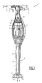
- FIGs 1 to 3 there is shown an apparatus 1 according to the invention, the type commonly called "mixer”.
- This mixer comprises a housing 3 forming a handle, a food processing tool 5, and an electric motor 7, housed in the housing 3.
- the tool 5 comprises a casing tube 11 detachably attached to the casing 3 at one of its ends, a drive shaft 13 rotatably mounted coaxially in the tube 11, and a product treatment member 15 such as a blade or a knife, integral with the shaft 13.
- the product treatment member 15 protrudes from the tube 11, on the side of the free end of the latter.
- the tool 5 further comprises a bell 17, secured to the tube 11 at the free end thereof, and provided to protect access to the member 15.
- the motor 7 is connected to the shaft 13 so as to be able to rotate the treatment member 15.
- the axis X common to the shaft 13 and to the tube 11, which also represents the axis of rotation of the treatment member 15 is generally oriented vertically, the treatment member 1 being turned downwards.
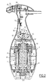
- the motor 7 is preferably a motor of universal type, having at the rotor 21 a motor shaft (or motor output shaft) 23, oriented axially, and an integral winding 25.
- the stator 27 of the motor 7 comprises a winding 29 extending radially outwardly of the rotor winding 25.
- the motor shaft 23 is integral with a coupling piece 31 provided with a drive shape, designed to receive a form of drive complementary to the shaft 13 of the tool 5, so as to form a detachable rotational connection between the shaft 13 and the motor shaft 23.
- the apparatus 1 further comprises a ventilation device provided for cooling the engine during operation of the apparatus.
- This device comprises, in a lower portion of the casing, air inlet orifices 33 arranged peripherally, radially outwardly with respect to the shaft 23.
- the ventilation device comprises, in a portion of the casing 3 located more upwards, air outlet orifices 35, arranged peripherally, radially outwardly with respect to the shaft 23.
- the rotor winding 25 and the stator winding 29 extend axially between the air inlets 33 and the air outlets 35.
- the ventilation device further comprises an axial fan 37 and a radial fan 39 integral with the shaft 23, and arranged on the side of the upper end thereof.
- the radial fan 39 is arranged substantially at the axial level of the air outlets 35, whereas the axial fan 37 is arranged immediately upstream, considering the air flow direction of the air inlets 33 to the air outlets 35.
- the axial fan 37 is located below the radial fan, more precisely between the latter and the rotor and stator coils 29.
- the axial fan 37 during its rotation, contributes to an air flow in a generally axial direction, the air streams flowing helically around the X axis.
- the radial fan 39 during its rotation, receives as input this generally axial air flow from the axial fan, and directs it substantially radially towards the air outlet orifices 35.
- the path of the cooling air streams, set in motion by the rotation of the fans 37, 39, is shown schematically in FIG. 3.
- cooling air circulates essentially radially from the air inlets 33 towards the shaft 23, and then circulates essentially axially inside the engine 7, passing between the stator windings 29. and the rotor 25.
- the air then flows through the axial fan 37, and is radially diffused from the axis to the peripheral air outlets 35 by the radial fan 39.
- annular wall 41 of the ventilation device is fixed inside the casing 3, so as to extend radially between the stator 27 and the casing 3.
- This wall 41 prevents the circulation of air, since the air inlets 33, between the stator 27 and the corresponding part of the housing surrounding the latter.
- the wall 41 thus forces the flow of air, from the air inlets 33, between the rotor 21 and the stator 27.
- the ventilation device comprises, extending axially between the stator 27 and the axial fan 37, an axial tubular duct 43 making it possible to channel the air axially between the stator and the fan 37, substantially up to the level of air outlets 35, to avoid recirculation of air inside the housing to the inputs 33 (downwards).
- the combination of the axial fan 37 and the radial fan 39 substantially increases the efficiency of the fan device with a constant shaft rotation speed, by substantially increasing the flow rate of air passing through the preferred heating zones. located at the coils 25, 29.
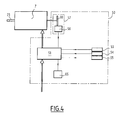
- the apparatus 1 further comprises a device 50 for controlling and controlling the motor 7, which device has been shown diagrammatically in FIG. 4.
- control and control device 50 For the following description of this control and control device 50, reference is made more particularly to FIGS. 2 and 4.
- the control and control device 50 comprises an electronic control element 51 of the motor, adapted to control the power supply of the latter.
- the control member 51 is in the form of a printed circuit board, arranged and fixed inside the housing 3.
- the control and control device 50 further comprises, arranged in an upper portion of the housing and operable by the user, a button 53 for starting, a button 54 for stopping the motor, and buttons 55 for adjusting the the set speed of the motor. These buttons 53, 54, 55 are electrically connected to the control member 51, so that the latter receives respective input signals representative of their state.
- the control and control device 50 is further provided with a non-contact measuring device 57 for the speed of rotation of the motor shaft 23, this device 57 being of magnetic type. It more precisely comprises a Hall effect sensor 58 fixed with respect to the casing 3, and an associated coding member 59, integral in rotation with the motor shaft 23.
- the coding member 59 is for example a bar of magnetic or magnetizable material, for example a bar of soft iron, capable of deflecting the magnetic field lines of a magnet placed nearby.
- the coding member 59 is attached to the upper end of the radial fan 39.
- the Hall effect sensor 58 comprises a source member 61, such as a permanent magnet, producing a magnetic field, and a member 62 sensitive to the magnetic field of the source member 61.
- the sensitive member 62 which is electrically powered, is the seat of a Hall voltage that is measured. This measurement is transmitted to the control member 51, to which the sensor 58 is connected.
- the magnet 61 and the sensitive member 62 which are for example fixed on the printed circuit board 51, are spaced apart from each other, so that the coding member 59, during its rotation integral with the motor shaft 23, passes between the magnet 61 and the sensitive member 62. In this case, only the two end portions of the bar forming coding member 59 pass alternately between the magnet 61 and the body sensitive 62.
- the coding member 59 influences the sensor 58 by varying the Hall voltage in the sensitive member 62.
- the control member 51 is adapted, during engine operation, to receive the speed reference value of the control member 55, as well as the measured speed value of the sensor 58, and to regulate the speed of rotation of the motor on the set speed, using the speed measured as control variable.
- the control and control device 50 further comprises an overload indicator 65, for example a pilot light, as shown in FIG. 2, electrically connected to the control member 51.
- an overload indicator 65 for example a pilot light, as shown in FIG. 2, electrically connected to the control member 51.
- the control member 51 is adapted to calculate the difference between the setpoint value and the measured value of the speed of rotation of the motor shaft 23, received respectively from the adjusting member 55 and the sensor 58.
- control member 51 activates the overload indicator 65, in this case triggers the emission of a light signal, when the difference between the setpoint value and the measured value of the speed exceeds a predetermined threshold value, and this during a first predetermined duration.
- the overload flag 65 may be activated when the measured speed remains 10 to 20% (preferably 15%) lower than the set value for 1 minute or more.
- control member 51 can be adapted to cut off the power supply of the motor 7 when the difference between the reference speed and the measured speed exceeds this same threshold value (for example from 10 to 20%, and preferably 15%) for a second predetermined duration, greater than the first.
- this same threshold value for example from 10 to 20%, and preferably 15%
- the second predetermined duration may for example be of the order of 1 minute 30, or 2 minutes.
- the user can be warned of a risk of overheating of the engine, and the stop of the motor can be triggered automatically when these risks of overheating become critical.
Landscapes
- Engineering & Computer Science (AREA)
- Power Engineering (AREA)
- Motor Or Generator Cooling System (AREA)
Applications Claiming Priority (1)
| Application Number | Priority Date | Filing Date | Title |
|---|---|---|---|
| FR0508829A FR2890252B1 (fr) | 2005-08-29 | 2005-08-29 | Appareil electrique de traitement de produits alimentaires dote d'un dispositif de ventilation perfectonne. |
Publications (1)
| Publication Number | Publication Date |
|---|---|
| EP1760862A1 true EP1760862A1 (de) | 2007-03-07 |
Family
ID=36293548
Family Applications (1)
| Application Number | Title | Priority Date | Filing Date |
|---|---|---|---|
| EP06291359A Withdrawn EP1760862A1 (de) | 2005-08-29 | 2006-08-25 | Elektrisches Lebensmittelverarbeitungsgerät mit einer verbesserten Kühlungsvorrichtung |
Country Status (3)
| Country | Link |
|---|---|
| US (1) | US20070046111A1 (de) |
| EP (1) | EP1760862A1 (de) |
| FR (1) | FR2890252B1 (de) |
Cited By (1)
| Publication number | Priority date | Publication date | Assignee | Title |
|---|---|---|---|---|
| EP2116162A1 (de) * | 2008-05-07 | 2009-11-11 | Seb SA | Haushaltsgerät zur Essenszubereitung, das zum Halten in der Hand konzipiert und mit einem Kabelführungselement ausgestattet ist |
Families Citing this family (9)
| Publication number | Priority date | Publication date | Assignee | Title |
|---|---|---|---|---|
| EP2130469A1 (de) * | 2008-06-06 | 2009-12-09 | Ian Geoffrey Wilson | Handmixgerät mit Schalteranordnung |
| JP5522504B2 (ja) * | 2008-09-29 | 2014-06-18 | 日立工機株式会社 | 電動工具 |
| DE102012112892A1 (de) | 2012-12-21 | 2014-07-10 | Dr. Ing. H.C. F. Porsche Aktiengesellschaft | Elektromaschine |
| CN105056822A (zh) * | 2015-09-07 | 2015-11-18 | 惠阳亚伦塑胶电器实业有限公司 | 手持搅拌机 |
| CN211749120U (zh) * | 2017-03-21 | 2020-10-27 | 光达家电用品公司 | 与一个或多个混合装置一起使用的手持混合器和具有软化功能的混合器 |
| CN109550438A (zh) * | 2017-08-06 | 2019-04-02 | 汪思芳 | 一种搅拌效果好的制备机 |
| CN110367843A (zh) * | 2018-04-13 | 2019-10-25 | 九阳股份有限公司 | 一种豆浆机 |
| US11064839B2 (en) * | 2018-04-20 | 2021-07-20 | Hamilton Beach Brands, Inc. | Blender with baffle for reducing noise |
| FR3083688B1 (fr) | 2018-07-13 | 2020-06-19 | Seb S.A. | Systeme de ventilation d'un appareil electro-menager portatif de traitement de preparations alimentaires, de type mixeur / batteur |
Citations (5)
| Publication number | Priority date | Publication date | Assignee | Title |
|---|---|---|---|---|
| US4680493A (en) * | 1984-06-23 | 1987-07-14 | Dr. Ing. H.C.F. Porsche Aktiengesellschaft | Ventilating device for a generator |
| DE3942083A1 (de) * | 1989-12-20 | 1991-06-27 | Licentia Gmbh | Handgefuehrte elektrowerkzeugmaschine |
| EP0444908A2 (de) * | 1990-02-28 | 1991-09-04 | Black & Decker Inc. | Anker für einen elektrischen Motor |
| EP0575763A1 (de) * | 1992-06-20 | 1993-12-29 | Robert Bosch Gmbh | Laufrad für einen Radiallüfter |
| EP1230883A2 (de) * | 2000-12-05 | 2002-08-14 | Sammic, S.A. | Verbesserte Küchenmaschine zum Zerkleinern und Mischen von Nahrungsmitteln |
Family Cites Families (12)
| Publication number | Priority date | Publication date | Assignee | Title |
|---|---|---|---|---|
| US2319194A (en) * | 1941-12-05 | 1943-05-11 | Casco Products Corp | Electric motor |
| US3333831A (en) * | 1966-05-13 | 1967-08-01 | Burton B Chapman | Power-driven fluid displacement apparatus |
| DE2649878B2 (de) * | 1976-10-29 | 1980-03-06 | Kenwood Manufacturing Co. Ltd., London | Mixgerät für den Haushalt |
| DE3937853A1 (de) * | 1989-11-14 | 1991-05-16 | Braun Ag | Elektrische zahnbuerste mit loesbarem buerstenteil |
| DE19504638A1 (de) * | 1995-02-13 | 1996-08-14 | Braun Ag | Verfahren für ein Arbeitsgerät, insbesondere Stabmixer, zum Rühren oder Zerkleinern von Nahrungsmitteln in einem Behälter |
| US6193404B1 (en) * | 1997-07-16 | 2001-02-27 | Robot-Coupe (S.N.C.) | Dipping mixer |
| US5863118A (en) * | 1997-07-29 | 1999-01-26 | Conair Corporation | Blender with extendible housing |
| DE19750813C2 (de) * | 1997-11-17 | 2002-06-13 | Braun Gmbh | Arbeitsgerät zum Rühren oder Zerkleinern von Nahrungsmitteln, insbesondere Stabmixer |
| DE19812541A1 (de) * | 1998-03-21 | 1999-09-30 | Braun Gmbh | Glockenförmige Abschirmung für die Verwendung in einem Haushaltsgerät, insbesondere Stabmixer oder Handrührer |
| US20050029685A1 (en) * | 2003-08-06 | 2005-02-10 | Hang Zhao | Beverage mixer/aerator |
| US7172334B2 (en) * | 2003-12-11 | 2007-02-06 | Conair Corporation | Hand held blender |
| USD534032S1 (en) * | 2006-01-18 | 2006-12-26 | Conair Corporation | Stick blender |
-
2005
- 2005-08-29 FR FR0508829A patent/FR2890252B1/fr not_active Expired - Fee Related
-
2006
- 2006-08-25 EP EP06291359A patent/EP1760862A1/de not_active Withdrawn
- 2006-08-28 US US11/467,691 patent/US20070046111A1/en not_active Abandoned
Patent Citations (5)
| Publication number | Priority date | Publication date | Assignee | Title |
|---|---|---|---|---|
| US4680493A (en) * | 1984-06-23 | 1987-07-14 | Dr. Ing. H.C.F. Porsche Aktiengesellschaft | Ventilating device for a generator |
| DE3942083A1 (de) * | 1989-12-20 | 1991-06-27 | Licentia Gmbh | Handgefuehrte elektrowerkzeugmaschine |
| EP0444908A2 (de) * | 1990-02-28 | 1991-09-04 | Black & Decker Inc. | Anker für einen elektrischen Motor |
| EP0575763A1 (de) * | 1992-06-20 | 1993-12-29 | Robert Bosch Gmbh | Laufrad für einen Radiallüfter |
| EP1230883A2 (de) * | 2000-12-05 | 2002-08-14 | Sammic, S.A. | Verbesserte Küchenmaschine zum Zerkleinern und Mischen von Nahrungsmitteln |
Cited By (2)
| Publication number | Priority date | Publication date | Assignee | Title |
|---|---|---|---|---|
| EP2116162A1 (de) * | 2008-05-07 | 2009-11-11 | Seb SA | Haushaltsgerät zur Essenszubereitung, das zum Halten in der Hand konzipiert und mit einem Kabelführungselement ausgestattet ist |
| FR2930881A1 (fr) * | 2008-05-07 | 2009-11-13 | Seb Sa | Appareil electromenager de preparation culinaire prevu pour etre tenu a la main muni d'un element guide cordon |
Also Published As
| Publication number | Publication date |
|---|---|
| FR2890252A1 (fr) | 2007-03-02 |
| US20070046111A1 (en) | 2007-03-01 |
| FR2890252B1 (fr) | 2007-11-30 |
Similar Documents
| Publication | Publication Date | Title |
|---|---|---|
| EP1760862A1 (de) | Elektrisches Lebensmittelverarbeitungsgerät mit einer verbesserten Kühlungsvorrichtung | |
| CN107000184B (zh) | 电动工具 | |
| US4949022A (en) | Solid state DC fan motor | |
| US9718180B2 (en) | Power tool having improved motor and controller cooling | |
| EP2946887B1 (de) | Teilchentrennanordnung für ein elektrowerkzeug | |
| US20200230723A1 (en) | Blower for circular saw | |
| EP2582576B1 (de) | Stromversorgung für die vom triebwerksrotor getragenen geräte | |
| US8324765B2 (en) | Fluid-operated medical or dental handle with speed limiting | |
| EP2751910B1 (de) | Elektrische maschine mit verbesserter kühlung | |
| FR3042327B1 (fr) | Systeme de refroidissement d'un moteur electrique | |
| EP1760865A1 (de) | Elektrisches Gerät zum Bearbeiten von Nahrungsmitteln mit einem Drehzahlsensor für die Motorwelle | |
| US20050011366A1 (en) | Cotton candy machine toy | |
| US5675228A (en) | Methods and apparatus for controlling energization of a motor | |
| FR2580126A1 (en) | Hand-held electric tool e.g. saw, plane or polisher | |
| FR3000628A1 (fr) | Dispositif d'entrainement electrique d'une charge | |
| CH435545A (fr) | Tour dentaire portatif | |
| EP3995056B1 (de) | Elektrisches kochgerät, das ein arbeitswerkzeug umfasst | |
| WO2015025749A1 (ja) | モータ | |
| EP2779364A1 (de) | Elektronisch gesteuerter Motor mit Permanentmagnetrotor | |
| FR2790614A1 (fr) | Generateur de courant electrique a vitesse de rotation variable et tension et (ou) frequence constantes | |
| JP2021014002A (ja) | 安全装置付電動工具及び電動工具用安全装置 | |
| FR3064134B1 (fr) | Compresseur de suralimentation electrique avec support d'aimant | |
| FR3123573A1 (fr) | Dispositif de dosage de grain à débit contrôlé | |
| FR2709888A1 (fr) | Alternateur de véhicule équipé d'un ventilateur de refroidissement. | |
| FR2515357A1 (fr) | Generatrice tachymetrique pour outils electriques |
Legal Events
| Date | Code | Title | Description |
|---|---|---|---|
| PUAI | Public reference made under article 153(3) epc to a published international application that has entered the european phase |
Free format text: ORIGINAL CODE: 0009012 |
|
| AK | Designated contracting states |
Kind code of ref document: A1 Designated state(s): AT BE BG CH CY CZ DE DK EE ES FI FR GB GR HU IE IS IT LI LT LU LV MC NL PL PT RO SE SI SK TR |
|
| AX | Request for extension of the european patent |
Extension state: AL BA HR MK YU |
|
| 17P | Request for examination filed |
Effective date: 20070726 |
|
| 17Q | First examination report despatched |
Effective date: 20070823 |
|
| AKX | Designation fees paid |
Designated state(s): AT BE BG CH CY CZ DE DK EE ES FI FR GB GR HU IE IS IT LI LT LU LV MC NL PL PT RO SE SI SK TR |
|
| STAA | Information on the status of an ep patent application or granted ep patent |
Free format text: STATUS: THE APPLICATION IS DEEMED TO BE WITHDRAWN |
|
| 18D | Application deemed to be withdrawn |
Effective date: 20080410 |