EP1760894A2 - Verfahren und Vorrichtung zur Steuerung des Leistungsverbrauches von an ein drahtloses Netzwerk angeschlossenen tragbaren Vorrichtungen - Google Patents
Verfahren und Vorrichtung zur Steuerung des Leistungsverbrauches von an ein drahtloses Netzwerk angeschlossenen tragbaren Vorrichtungen Download PDFInfo
- Publication number
- EP1760894A2 EP1760894A2 EP06119589A EP06119589A EP1760894A2 EP 1760894 A2 EP1760894 A2 EP 1760894A2 EP 06119589 A EP06119589 A EP 06119589A EP 06119589 A EP06119589 A EP 06119589A EP 1760894 A2 EP1760894 A2 EP 1760894A2
- Authority
- EP
- European Patent Office
- Prior art keywords
- wireless device
- data
- time
- frame
- portable wireless
- Prior art date
- Legal status (The legal status is an assumption and is not a legal conclusion. Google has not performed a legal analysis and makes no representation as to the accuracy of the status listed.)
- Withdrawn
Links
Images




Classifications
-
- H—ELECTRICITY
- H04—ELECTRIC COMMUNICATION TECHNIQUE
- H04W—WIRELESS COMMUNICATION NETWORKS
- H04W52/00—Power management, e.g. Transmission Power Control [TPC] or power classes
- H04W52/02—Power saving arrangements
- H04W52/0209—Power saving arrangements in terminal devices
- H04W52/0212—Power saving arrangements in terminal devices managed by the network, e.g. network or access point is leader and terminal is follower
- H04W52/0216—Power saving arrangements in terminal devices managed by the network, e.g. network or access point is leader and terminal is follower using a pre-established activity schedule, e.g. traffic indication frame
-
- H—ELECTRICITY
- H04—ELECTRIC COMMUNICATION TECHNIQUE
- H04W—WIRELESS COMMUNICATION NETWORKS
- H04W52/00—Power management, e.g. Transmission Power Control [TPC] or power classes
- H04W52/02—Power saving arrangements
- H04W52/0209—Power saving arrangements in terminal devices
- H04W52/0212—Power saving arrangements in terminal devices managed by the network, e.g. network or access point is leader and terminal is follower
-
- H—ELECTRICITY
- H04—ELECTRIC COMMUNICATION TECHNIQUE
- H04W—WIRELESS COMMUNICATION NETWORKS
- H04W52/00—Power management, e.g. Transmission Power Control [TPC] or power classes
- H04W52/02—Power saving arrangements
- H04W52/0209—Power saving arrangements in terminal devices
- H04W52/0261—Power saving arrangements in terminal devices managing power supply demand, e.g. depending on battery level
- H04W52/0274—Power saving arrangements in terminal devices managing power supply demand, e.g. depending on battery level by switching on or off the equipment or parts thereof
- H04W52/028—Power saving arrangements in terminal devices managing power supply demand, e.g. depending on battery level by switching on or off the equipment or parts thereof switching on or off only a part of the equipment circuit blocks
- H04W52/0283—Power saving arrangements in terminal devices managing power supply demand, e.g. depending on battery level by switching on or off the equipment or parts thereof switching on or off only a part of the equipment circuit blocks with sequential power up or power down of successive circuit blocks, e.g. switching on the local oscillator before RF or mixer stages
-
- Y—GENERAL TAGGING OF NEW TECHNOLOGICAL DEVELOPMENTS; GENERAL TAGGING OF CROSS-SECTIONAL TECHNOLOGIES SPANNING OVER SEVERAL SECTIONS OF THE IPC; TECHNICAL SUBJECTS COVERED BY FORMER USPC CROSS-REFERENCE ART COLLECTIONS [XRACs] AND DIGESTS
- Y02—TECHNOLOGIES OR APPLICATIONS FOR MITIGATION OR ADAPTATION AGAINST CLIMATE CHANGE
- Y02D—CLIMATE CHANGE MITIGATION TECHNOLOGIES IN INFORMATION AND COMMUNICATION TECHNOLOGIES [ICT], I.E. INFORMATION AND COMMUNICATION TECHNOLOGIES AIMING AT THE REDUCTION OF THEIR OWN ENERGY USE
- Y02D30/00—Reducing energy consumption in communication networks
- Y02D30/70—Reducing energy consumption in communication networks in wireless communication networks
Definitions
- the present invention relates to a technology for a wireless local area network (LAN) and, more particularly, to a method of and an apparatus for reducing power consumption in portable devices connected to a wireless LAN.
- LAN wireless local area network
- FIG. 1 illustrates the configuration of a wireless LAN implemented with a conventional general infrastructure.
- a plurality of portable devices 32, 33 and 34 can transmit and receive data through an access point (AP) 31 using the IEEE 802.11 series standard.
- the portable devices include a personal computer, a notebook computer, a cellular phone, and a personal digital assistant (PDA).
- the portable device 32 can transmit and receive data to and from another portable device 33 through a protocol under the IEEE 802.11 series standard.
- the portable device 32 allows users to conduct voice communication with a notebook computer 34 by transmitting and receiving a VoIP packet to and from the notebook computer 34.
- Korean Unexamined Patent Publication No. 2001-075670 discloses a method of reducing battery power consumption in a communication system, which includes determining whether a received and demodulated signal can be decoded, cutting off power supplied to a receiver if the signal cannot be decoded, and operating the receiver if the signal can be decoded.
- Korean Unexamined Patent Publication No. 1999-065379 discloses a wireless call system that determines whether a data arrangement is set in a previously set manner using a time slot number included in the header arrangement of a signal transmitted from a prior call system, and turns on a radio frequency (RF) module by supplying power if the data arrangement is set in the previous set manner.
- RF radio frequency
- U.S. Patent No. 5,355,518 discloses a receiver having a power-saving circuit that monitors channels in a power-saving mode to maintain the receiver either in a sleep mode or an operating mode, depending on whether an effective coded squelch signal (CSS) has been detected.
- the above-mentioned conventional methods have several problems, in that the conventional methods have been focused either on minimizing the power required during the data transmission or on a method of reducing duty-cycle by collecting idle time information and converting the operating mode of portable devices into a doze mode during the idle time.
- traffic requirements of an application program are not considered. Rather, emphasis has been put on optimizing data transmission or data reception. For this reason, it is difficult to reduce power consumption in the overall wireless system.
- the present invention provides a method of and apparatus for reducing power consumption in portable devices connected to a wireless local area network implemented with an IEEE 802.11 Distributed Coordination Function (DCF) standard.
- DCF Distributed Coordination Function
- a method of controlling power consumption in a portable wireless device that is operable to transmit and receive data to and from another portable wireless device in a predetermined unit time.
- the method includes a) receiving at least one data frame from the other portable wireless device within a range of a maximum reception mode time, b) transmitting at least one data frame to the other portable wireless device at an adjusted transmission rate according to traffic requirements or status information of the portable wireless device, and c) switching a current mode of the portable wireless device to a doze mode for a remaining time of the predetermined unit time, after operations a) and b) have been performed.
- a portable wireless device that is operable to transmit and receive data to and from another wireless device in a predetermined unit time.
- the portable wireless device includes means for receiving at least one data frame from the other portable wireless device within a range of a maximum reception mode time, means for transmitting at least one data frame to the other portable wireless device at an adjusted transmission rate according to traffic requirements or status information of the portable wireless device, and means for switching a current mode of the portable wireless device to a doze mode for a remaining time of the predetermined unit time, after the data have been received and transmitted.
- a portable wireless device operates under IEEE 802.11 DCF mode.
- the portable wireless device receives data transmission and reception requirements from an application program, defines a maximum delay time as a unit time, transmits a PS-Poll frame to an access point (AP), and receives data buffered in the AP. If there is no more data buffered in the AP, the portable wireless device transmits the buffered data.
- a wireless LAN modem provided in the portable wireless device is switched to a doze mode for the duration of the remaining time.
- An actual transmission rate and an actual reception rate are continuously measured so that data is transmitted at an adjusted transmission rate if there is a difference between the traffic requirements of the application program and the measured transmission and reception rates.
- the portable wireless device is set according to various kinds of status information provided from the wireless LAN modem and by referring to an energy-performance table optimally set for a wireless LAN.
- the portable wireless device transmits data using minimum power during data transmission.
- FIG. 2 is a block diagram illustrating the configuration of a portable wireless device 100 according to an exemplary embodiment of the present invention.
- the portable wireless device 100 includes an application 10, a wireless LAN modem 30, and a power-management module 20 provided between the application 10 and the wireless LAN modem 30.
- the portable wireless device 100 is configured to transmit and receive Media Access Control (MAC) service data unit (MSDU) between the application 10 and the wireless LAN modem 30. That is, if the wireless LAN modem 30 receives the MSDU corresponding to data supplied from the application 10, an MAC unit provided in the wireless LAN modem 30 adds a predetermined MAC header and a Physical Layer (PHY) header to the MSDU and modulates them prior to transmission.
- the wireless LAN modem 30 demodulates a received RF signal, eliminates the PHY header and the MAC header to recover the MSDU, and supplies the MSDU to the application 10.
- MAC Media Access Control
- the MSDU is transmitted and received between the application 10 and the wireless LAN modem 30 in the same manner as the existing portable wireless devices.
- the power management module 20 is provided between the application 10 and the wireless LAN modem 30 to efficiently manage power consumption during data transmission and reception between the portable wireless device 100 and another portable wireless device.
- the wireless LAN modem 30 processes an MAC layer and a PHY layer in accordance with the IEEE 802.11 series standard.
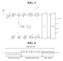
- FIG. 3 illustrates the configuration of the wireless LAN modem 30 according to an exemplary embodiment of the present invention.
- the wireless LAN modem 30 includes at least one antenna 1 and a low-noise amplifier (LNA) 2. Although a transmitting antenna and a receiving antenna may separately be provided, the wireless LAN modem 30 further includes a switch 7 if one antenna is used for both transmission and reception, as shown in FIG. 3. Here, the switch 7 switches a transmission mode to a reception mode and vice versa. Referring to FIG. 3, if the wireless LAN modem 30 is switched to a state "a,” it is switched to a reception mode. On the other hand, if the wireless LAN modem 30 is switched to a state "b,” it is switched to a transmission mode.
- LNA low-noise amplifier
- a wireless LAN radio frequency (RF) signal is received by the antenna 1 and amplified by the LNA 2.
- the amplified RF signal is then output to an orthogonal demodulator 3.
- the orthogonal demodulator 3 down-converts the RF signal into a baseband signal. To this end, the RF signal is multiplied by a local oscillator signal Lo1.
- the local oscillator signal Lo1 is supplied by a voltage controlled oscillator (VCO).
- VCO voltage controlled oscillator
- PLL phase-locked loop
- the baseband signal supplied by the orthogonal demodulator 3 is input to a variable gain amplifier (VGA) 5.
- VGA 5 amplifies the baseband signal through an auto-gain control (AGC).
- AGC auto-gain control
- the VGA 5 allows gain control within a range greater than that of the LNA 2.
- One VGA 5 or a plurality of VGAs may be provided.
- a low-pass filter (LPF) 4 performs low-pass filtering on the signal supplied from the VGA 5, to separate a frequency band having actual data from the supplied signal.
- An output buffer 6 controls level and delay of the signal supplied from the LPF 4 and supplies the signal to an analog-to-digital converter (ADC) 6.
- ADC analog-to-digital converter
- the ADC 6 converts the signal into a digital signal and supplies the digital signal to a baseband processor (BBP) 8.
- BBP baseband processor
- the BBP 8 processes the digital signal to recover the MPDU and supplies the MPDU to the MAC unit 9.
- the MAC unit 9 parses the MAC header of the MPDU and supplies data having eliminated with the MAC header, the MSDU, to the application 10.
- the MAC unit 9 receives the MSDU from the application 10 and adds the MAC header to the MSDU, and then outputs the MSDU having the MAC header to the BBP 8.
- the BBP 8 adds a PHY header to the MPDU to generate a PHY protocol data unit (PPDU) and outputs the PPDU to a digital-to-analog converter (DAC) 16.
- the DAC 16 converts digital data supplied from the BBP 8, i.e., the PPDU, into an analog signal.
- the LPF 14 performs low-pass filtering on the signal output from the DAC 16 and extracts a frequency band corresponding to the signal.
- a VGA 15 amplifies the signal output from the LPF 14 through auto-gain control.
- An orthogonal modulator 13 multiplies a local oscillator signal Lo2 supplied from the VCO by the signal output from the VGA 15 and up-converts the signal into an RF signal band.
- a power amplifier 12 is a driving amplifier that amplifies the signal output from the orthogonal modulator 13. The amplified signal is then transmitted through the antenna 1 after passing through the switch 7.
- the power management module 20 according to an exemplary embodiment of the present invention will now be described in detail with reference to FIG. 2, in which signals "a” to “k” are defined as shown in Table 1.
- Main parameter for algorithm operation traffic requirements
- Main parameter for algorithm operation average transmission rate d Adjusted data transmission rate for satisfying traffic requirements e MAC/PHY MIB values provided from wireless LAN modem
- State parameter processed to retrieve energy-performance table g A set of retrieved optimal control parameter values h
- k Control signal for switching wireless LAN modem to a doze mode and an idle mode
- a traffic-requirement setting unit 21 receives traffic requirements for data transmission and reception from the application 10 and determines a required parameter value.
- the traffic-requirement setting unit 21 may receive the traffic requirements through an application programming interface (API) or application-program profile information.
- the traffic requirements include an average data-transmission rate R req Tx (Mbps), an average data-reception rate R req Rx (Mbps), and a maximum delay time I req delay .
- the average data-transmission rate R req Tx (Mbps) means a transmission rate at which streaming data is transmitted at an average level.
- the average data-reception rate R req Rx (Mbps) means a reception rate at which streaming data is received at an average level.
- the maximum delay time means a maximum allowable time required to display streaming data without delay. Therefore, the portable wireless device 100 receives a next streaming data packet before the lapse of the maximum delay time after receiving a previous streaming data packet.
- the traffic-requirement setting unit 21 calculates output information from the requirements.
- the output information includes a unit time T u , average data L T ⁇ x avg to be transmitted per unit time, average data L R ⁇ x avg to be received per unit time, a maximum reception-mode time T R ⁇ x max , and a minimum doze time T doze min .
- the unit time T u means the greatest value of multiples of a beacon interval I b within the range of the maximum delay time I delay req . For example, supposing that the maximum delay time is 200ms and the beacon interval is 30ms, the unit time T u will be 180ms.
- the average data L T ⁇ x avg is obtained by multiplying R T ⁇ x req and T u
- the average data L R ⁇ x avg is obtained by multiplying R R ⁇ x req and T u .
- An average transmission rate R T ⁇ x phy that can actually be set at the PHY node of the portable wireless device 100 is greater than a sum of R T ⁇ x req and R R ⁇ x req , and smaller than the maximum transmission rate of the wireless LAN modem.
- the maximum reception-mode time T R ⁇ x max means a maximum time in which data is continuously received within the unit time T u .
- the portable wireless device 100 can be maintained in the reception mode for the time excluding the time for transmitting L T ⁇ x avg within the unit time T u . Therefore, T R ⁇ x max can be expressed as Equation 1.
- T R ⁇ x max T u ⁇ L T ⁇ x avg R T ⁇ x req
- the doze time T doze min means a minimum time in the doze mode and the idle mode that has an effect of reducing power consumption. If the time of the doze mode is too short, the energy consumed by switching from the doze mode to the idle mode is greater than the energy consumed in the idle mode. Therefore, if the remaining time in the unit time T u is less than the doze time, switching to the doze mode can have an effect of reducing power consumption.
- a status-parameter collecting unit 24 collects various kinds of status information related to the operation status of a wireless LAN channel from a wireless LAN interface.
- the status information can be supplied from the wireless LAN modem 30 in a management information base (MIB) type.
- MIB management information base
- the status-parameter collecting unit 24 collects required status information from the wireless LAN modem 30 in accordance with a request from a control-parameter determining unit 23.
- the status-parameter collecting unit 24 processes the status information to obtain a previously defined status parameter and supplies the status parameter to the control-parameter determining unit 23.
- the status-parameter collecting unit 24 periodically reads the number of fragment transmission times C TxFrags and the total number of retransmission times C retry from the wireless LAN modem 30 and calculates the number of retransmission times C RPF i per frame to be transmitted, in accordance with Equation 2.
- C RPF i C retry i ⁇ C retry i ⁇ 1 C T ⁇ x ⁇ Frags i ⁇ C T ⁇ x ⁇ Frags i ⁇ 1
- information input to the status-parameter collecting unit 24 corresponds to status parameters [ s 1 ,.., s l ] of low level supplied from the wireless LAN modem 30.
- Information output to the control-parameter determining unit 23 corresponds to status parameters [ S 1 ,.., S m ] processed to be referred to the energy-performance table.
- the status parameters [ s 1 ,.., s l ] of low level include a Received Signal Strength Indication (RSSI), a short retry count (SRC), a long retry count (LRC), and the number of retransmission times C RPF per frame.
- RSSI Received Signal Strength Indication
- SRC short retry count
- LRC long retry count
- the control-parameter determining unit 23 obtains a value of a control parameter referring to a predetermined energy-performance table 26.
- the control parameter controls minimization of power required within the range that a given traffic requirement is satisfied based on the wireless LAN status information and traffic requirements. That is, optimized control parameters [ C 1 ,.., C n ] are retrieved in such a manner that the energy-performance table 26 is retrieved based on the status parameters [ S 1 ,.., S m ] and the target data transmission rate R T ⁇ x rev , each time data is transmitted.
- the input information of the control-parameter determining unit 23 corresponds to R T ⁇ x rev , [ S 1 ,.., S m ] and the retrieved results of the energy-performance table 26, when the output information supplied to a control-parameter application unit 25 corresponds to a set of the retrieved optimized control parameter values.
- the control parameters [ C 1 ,.., C n ] include parameters shown in Table 2.
- the energy-performance table 26 corresponds to a predetermined trade-off table that has different optimized energy performances set during the manufacturing process. Each row of the table includes power consumption, data transmission rates, values of control parameters, and values of status parameters. The procedure for retrieving the optimized control parameter values by referring to the energy-performance table 26 by the control-parameter determining unit 23 will be described later.
- the control-parameter application unit 25 sets the control parameter values that can be controlled by the wireless LAN interface. That is, the control-parameter application unit 25 sets the optimized control parameter values [ C 1 ,.., C n ] supplied from the control-parameter determining unit 23 for each control parameter of the wireless LAN modem 30.
- a doze-mode control unit 22 calculates the idle time and switches the wireless LAN to the doze mode for the duration of the idle time in which data transmission and reception traffics through the wireless LAN is monitored. That is, the doze-mode control unit 22 calculates and accumulates the quantity of data transmitted (or received) and the required time based on the traffic requirements, at the time when the data transmission (or reception) is finished. If the time obtained by subtracting the accumulated transmission time and the accumulated reception time from the current unit time is greater than the minimum doze time T doze min , the doze-mode control unit 22 controls the wireless LAN modem 30 to switch to the doze mode for the corresponding time.
- Information input from the traffic-requirement setting unit 21 to the doze-mode control unit 22 includes L T ⁇ x avg , L R ⁇ x avg , T u , T R ⁇ x max , T doze min , R T ⁇ x req , and R R ⁇ x req
- Information output from the doze-mode control unit 22 to the parameter determining unit 23 includes the target data-transmission rate R T ⁇ x rev .
- Information output from the doze-mode control unit 22 to the wireless LAN modem 30 includes a control signal for controlling the wireless LAN modem 30 under the doze mode.
- the doze-mode control unit 22 initiates a parameter L T ⁇ x acc and a parameter L R ⁇ x acc to 0.
- the parameter L T ⁇ x acc represents the accumulated length of the transmission data for the unit time while the parameter L R ⁇ x acc represents the accumulated length of the reception data for the unit time.
- the doze-mode control unit 22 transmits a PS-Poll frame to the AP through the wireless LAN modem 30 and receives all the data buffered in the AP.
- the doze-mode control unit 22 continues to receive the data as long as T R ⁇ x max is not exceeded and "more data" bit is included in the MAC header of the received data is 1.
- the doze-mode control unit 22 transmits all the data in a transmission queue (not shown) from the portable wireless device 100 after the data reception is finished. In this way, after the data reception and transmission, the remaining time T u left within T u is calculated to determine whether the remaining time T u left is greater than T doze min .
- the doze-mode control unit 22 continues to control the wireless LAN modem 30 under the doze mode for the remaining time T u left .
- the remaining time T u left can be calculated in such a manner that the starting time of T u is subtracted from the current time and the result is subtracted from T u .
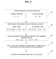
- each period in which the portable wireless device 100 operates for the unit time T u is as shown in FIG. 4.
- the reception period and the transmission period are collected (i.e., all the data are transmitted after receiving all the data within the unit time) so that the maximum doze period can be obtained.
- the parameters of the wireless LAN modem 30 includes the control parameters [ C 1 ,.., C n ] and the status parameters [ S 1 ,.., S m ] as mentioned above.
- transmission energy E Tx d is determined by a function f energy having the control parameters and the status parameters as independent parameters.
- Transmission performance R Tx d is determined by a function f perf having the control parameters and the status parameters as independent parameters.
- the functions f energy and f perf may be determined by a predetermined algorithm that will be described later. That is, the transmission energy E Tx d and the transmission performance R Tx d may be determined in such a manner that the energy and performance corresponding to control parameters having a specific value and status parameters having a specific value are repeatedly measured to obtain an arbitrary control parameter value and an arbitrary status parameter value.
- parameter sets (tuples) including all available parameter values are calculated S3.
- One tuple includes control parameters [ C 1 ,.., C n ], status parameters [ S 1 ,.., S m ], and functions f energy and f perf corresponding to the control parameters and the status parameters.
- a tuple that corresponds to the least energy consumption is selected from the plurality of tuples S4, and the selected tuple sets an energy-performance table S5.
- tuples including all available parameter values are displayed on a coordinate plane having a horizontal axis of R Tx d and a vertical axis of E Tx d as shown in FIG. 6.
- the tuple 64 corresponding to the minimum energy consumption is selected in the operation S4.
- tuples 64, 65, 66, 67 and 68 that correspond to the least energy consumption under the given performance can be selected in accordance with each performance.
- These tuples 64, 65, 66, 67 and 68 set the enery-efficiency table.
- Table 3 shows four frame patterns divided depending on the packet size L d , request to send (RTS), threshold value K RtsThr , and fragmentation threshold value K FragThr in a distributed coordination function (DCF) mode under the IEEE 802.11 series standard.
- Table 3 Four Frame Patterns in DCF Mode C Condition RTS/CTS Fragmen tation Description a s e 1 L d ⁇ K FragThr , Both RTS/CTS frame exchange and fragmentation are not performed.
- both Request To Send/Clear To Send (RTS/CTS) frame exchange and fragmentation are not performed as shown in FIG. 7.
- the portable wireless device 100 has transmitted a data frame to the AP 200 but has not received acknowledgement (ACK) from the AP 200.
- the portable wireless device 100 retransmits the data frame to the AP 200.
- the portable wireless device 100 receives ACK from the AP 200 after Short Inter-Frame Space (SIFS), and undergoes back-off after Distributed Inter-Frame Space (DIFS).
- SIFS Short Inter-Frame Space
- DIFS Distributed Inter-Frame Space
- R Tx d can be defined in such a manner that the packet size L d is divided by the total elapsed time.
- R Tx d can be obtained by Equation 3.
- R T ⁇ x d ⁇ L d T total T ⁇ x L d T d + T AckTimeout ⁇ C RPF + T d + T SIFS + T ack + T DIFS + T C ⁇ W
- T d means a time required to transmit the data frame and T AckTimeout means an ACK time-out time.
- T SIFS means a time required for SIFS
- T DIFS a time required for DIFS
- T ack a time required for ACK transmission.
- T CW means a time required for a contention window.
- E Tx d means the power consumed during transmission and can be expressed as Equation 4.
- E T ⁇ x d E P ⁇ A d + E RFE T ⁇ x , d + E DSP T ⁇ x , d
- E Tx d may be divided into an energy E P ⁇ A d consumed by a power amplifier, an energy E DSP T ⁇ x , d consumed by a digital signal processor (DSP), and an energy E RFE T ⁇ x , d consumed by other units related to transmission.
- E P ⁇ A d consumed by a power amplifier an energy E DSP T ⁇ x , d consumed by a digital signal processor (DSP), and an energy E RFE T ⁇ x , d consumed by other units related to transmission.
- DSP digital signal processor
- E P ⁇ A d may also be expressed as Equation 5.
- P P ⁇ A T ⁇ x means power consumed when the portable wireless device 100 is in the transmission mode
- P P ⁇ A idle means power consumed when the portable wireless device 100 is in the idle mode.
- E P ⁇ A d P P ⁇ A T ⁇ x ⁇ T d + P P ⁇ A idle ⁇ T AckTimeout ⁇ C RPF + P P ⁇ A T ⁇ x ⁇ T d + P P ⁇ A idle ⁇ T SIFS + T ack + T DIFS + T C ⁇ W
- E RFE T ⁇ x , d can be expressed as Equation 6.
- Equation 6 it is supposed that one filter, two mixers, two low frequency filters, and two DACs are used for transmitting data.
- P RFE T ⁇ x P filt_ t ⁇ x + 2 ⁇ P mix + 2 ⁇ P lpf + 2 ⁇ P DAC
- P filt_tx , P mix , P lpf , P DAC , and E DSP T ⁇ x , d may previously be calculated according to hardware attributes. For example, they may be values specified in basic options of the wireless LAN modem 30.
- R Tx d can be defined in such a manner that the packet size L d is divided by the total elapsed time.
- R Tx d can be expressed by Equation 7.
- R T ⁇ x d ⁇ L d T total T ⁇ x L d T rts + T CtsTimeout ⁇ C RPF RTS + T rts + T cts + 2 ⁇ T SIFS + T d + T AckTimeout ⁇ C RPF + T d + T SIFS + T ack + T DIFS + T C ⁇ W
- Equation 7 T rts means a time required to transmit the RTS frame, T CtsTimeout CTS a time-out time, and C RPF RTS the number of retransmission times of the RTS frame per frame.
- E Tx d can be expressed as Equation 4, and referring to FIG. 8, E P ⁇ A d in Equation 4 can be expressed as Equation 8.
- RTS/CTS frame exchange is not performed but fragmentation is performed as shown in FIG. 9.
- the portable wireless device 100 intends to transmit a plurality of data fragments 1, 2 and 3 to the AP 200. However, the portable wireless device 100 does not receive ACK from the AP 200 for ACK time-out time after transmitting the data fragment 2 to the AP 200. Thus, it is assumed that the portable wireless device 100 retransmits the fragment 2 to the AP 200.
- R T ⁇ x d can be expressed by Equation 9.
- Equation 9 T Fi means a time required to transmit the data fragment 1 or 2
- T Fn means the last fragment, i.e., a time required to transmit the data fragment 3.
- E T ⁇ x d can be expressed as Equation 4
- E P ⁇ A d in Equation 4 can be expressed as Equation 10.
- both RTS/CTS frame exchange and fragmentation are performed as shown in FIG. 10.
- the portable wireless device 100 transmits a plurality of data fragments 1, 2 and 3 to the AP 200 after RTS/CTS frame exchange.
- R Tx d can be expressed by Equation 11.
- Equation 4 E T ⁇ x d can be expressed as Equation 4
- Equation 12 E P ⁇ A d in Equation 4 can be expressed as Equation 12.
- E P ⁇ A d P P ⁇ A T ⁇ x ⁇ T rts + P P ⁇ A idle ⁇ T CtsTimeout ⁇ C RPF RTS + P P ⁇ A T ⁇ x ⁇ T rts + P P ⁇ A idle ⁇ T cts + 2 ⁇ T SIFS + P P ⁇ A T ⁇ x ⁇ T F i + P P ⁇ A idle ⁇ T AckTimeout ⁇ C RPF + P P ⁇ A T ⁇ x ⁇ T F i + P P ⁇ A idle ⁇ T ack + 2 ⁇ T SIFS ⁇ ⁇ L d K Frag ⁇ T ⁇ h ⁇ r ⁇ + P P ⁇ A T ⁇ x ⁇ T F n + P P ⁇ A idle ⁇ T AckTimeout ⁇ C RPF + P P ⁇ A T ⁇ x ⁇ T F n + P P ⁇ A idle ⁇ T SIFS + T ack + T DIFS +
- each component of FIG. 2 or FIG. 3 may mean, but is not limited to, a software or hardware component, such as a field programmable gate-array (FPGA) or application-specific integrated circuit (ASIC).
- a component may advantageously be configured to reside on the addressable storage medium and configured to execute on one or more processors.
- the functionality provided for in the components may be separated into additional components or combined into a component that performs a specified function.
- FIG. 11 is a flowchart illustrating a method of controlling power consumption in a portable wireless device, according to an exemplary embodiment of the present invention. As shown in FIG. 4, the method includes the data reception operation S10, the data transmission operation S20, and the doze control operation S30. The operations are performed based on the greatest value of multiples of the beacon interval I b within the unit time T u , i.e., within the range of the maximum delay time I delay req .
- the portable wireless device 100 transmits the PS-Poll frame to the AP 200 and requests data reception S 11. If there are no reception data (N in S12), operation S21 is performed. If there are reception data (Y in S12), the portable wireless device 100 receives the data frame from the AP 200 S 13.
- the portable wireless device 100 determines whether the "more data bit" included in the MAC header of the received data frame is 1. If the "more data bit” included in the MAC header of the received data frame is 0 (N in S 14), there is no more data to be received data from the AP 200. In this case, operation S21 is performed. If the "more data bit” included in the MAC header of the received data frame is 1 (Y in S 14), there is more data to be received from the AP 200. In this case, it is determined whether the maximum reception mode time T R ⁇ x max has been exceeded S 15. If the maximum reception mode time T R ⁇ x max has been exceeded (Y in S 15), data reception is stopped even if there is more data to be received, and operation S21 is performed for the transmission operation. If the maximum reception mode time T R ⁇ x max has not been exceeded (N in S 15), the portable wireless device continues to receive the data frame S 13.
- the portable wireless device 100 determines whether there is data to be transmitted to the AP 200 S21. If there is no data to be transmitted (N in S21), operation S31 is performed. If there is more data to be transmitted (Y in S21), the portable wireless device collects the status parameters through the status-parameter collecting unit 24 S22, and obtains a set of optimized control parameter values for reducing power consumption referring to the collected status parameters and the energy-performance table 26 S23. The portable wireless device applies the obtained control parameter values to the wireless LAN modem 30. Therefore, the wireless LAN modem 30 transmits the data frame at a corrected transmission rate in accordance with the control parameter values S25. Subsequently, the operations prior to the operation S21 are repeated if there is more data to be transmitted during the remaining unit time T u .
- the operation S30 is performed for the remaining unit time T u .
- the portable wireless device 100 calculates the remaining time in the unit time T u S31. If the remaining time is less than the minimum doze time T doze min (N of S32), the current operation returns to the operation S11 to perform the operation for the next unit time T u . If the remaining time is greater than the minimum doze time T doze min (Y of S32), the wireless LAN modem 30 of the portable wireless device 100 switches from the current mode to the doze mode for the remaining time S33. If the remaining time lapses, the portable wireless device 100 returns to the idle mode S34, and the current operation returns to the operation S 11 to perform the operation for the next unit time T u .
- the wireless LAN modem is switched to the doze mode for the idle time considering the traffic requirements of the application program.
- the idle time is calculated based on the transmission and reception rates and the maximum delay time requirements, and the wireless LAN modem is switched to the doze mode for the calculated idle time. Also, data transmission is performed in such a manner that the actual transmission and reception rates are continuously monitored to calculate the adjusted transmission rate that satisfies the traffic requirements.
- the control parameter values of the wireless LAN modem are retrieved during data transmission, so as to correspond to the least energy required to satisfy the required data transmission rate, thereby minimizing power consumption.
Landscapes
- Engineering & Computer Science (AREA)
- Computer Networks & Wireless Communication (AREA)
- Signal Processing (AREA)
- Mobile Radio Communication Systems (AREA)
- Small-Scale Networks (AREA)
- Transceivers (AREA)
Applications Claiming Priority (1)
| Application Number | Priority Date | Filing Date | Title |
|---|---|---|---|
| KR1020050081464A KR100736044B1 (ko) | 2005-09-01 | 2005-09-01 | 무선 기기의 전력 제어 방법 및 장치 |
Publications (2)
| Publication Number | Publication Date |
|---|---|
| EP1760894A2 true EP1760894A2 (de) | 2007-03-07 |
| EP1760894A3 EP1760894A3 (de) | 2007-07-04 |
Family
ID=37461455
Family Applications (1)
| Application Number | Title | Priority Date | Filing Date |
|---|---|---|---|
| EP06119589A Withdrawn EP1760894A3 (de) | 2005-09-01 | 2006-08-25 | Verfahren und Vorrichtung zur Steuerung des Leistungsverbrauches von an ein drahtloses Netzwerk angeschlossenen tragbaren Vorrichtungen |
Country Status (5)
| Country | Link |
|---|---|
| US (1) | US20070049239A1 (de) |
| EP (1) | EP1760894A3 (de) |
| JP (1) | JP4495122B2 (de) |
| KR (1) | KR100736044B1 (de) |
| CN (1) | CN100525492C (de) |
Cited By (3)
| Publication number | Priority date | Publication date | Assignee | Title |
|---|---|---|---|---|
| EP1978765A1 (de) * | 2007-04-02 | 2008-10-08 | BRITISH TELECOMMUNICATIONS public limited company | Leistungsverwaltungsschema für mobile Kommunikationsgeräte |
| WO2010142849A1 (en) * | 2009-06-13 | 2010-12-16 | Nokia Corporation | Use of block acknowledgement policy for wireless networks |
| WO2014194509A1 (en) * | 2013-06-07 | 2014-12-11 | Empire Technology Development Llc | Adaptive transition of user equipment |
Families Citing this family (28)
| Publication number | Priority date | Publication date | Assignee | Title |
|---|---|---|---|---|
| US8170604B2 (en) * | 2006-06-27 | 2012-05-01 | Motorola Mobility, Inc. | Method and system for managing communications for a multi-mode communications device |
| US20080053207A1 (en) * | 2006-08-29 | 2008-03-06 | Motorola, Inc. | Control of transmission power in a communication device |
| US8665778B2 (en) * | 2006-11-30 | 2014-03-04 | Motorola Mobility Llc | Monitoring and control of transmit power in a multi-modem wireless communication device |
| US8059702B2 (en) * | 2006-11-30 | 2011-11-15 | Motorola Mobility, Inc. | Monitoring multiple modem transmission in a communication device |
| US8744519B2 (en) * | 2006-12-14 | 2014-06-03 | Motorola Mobility Llc | Multimodal phone data session management enhancement that alleviates dual transmission problems |
| KR100962113B1 (ko) | 2007-04-23 | 2010-06-10 | 삼성전자주식회사 | 이동통신 단말기에서 전력 증폭기를 고려한 상향링크스케줄링 방법 및 장치 |
| US7925903B2 (en) * | 2007-06-28 | 2011-04-12 | Microsoft Corporation | Media device power conservation |
| RU2503125C2 (ru) * | 2008-02-05 | 2013-12-27 | Конинклейке Филипс Электроникс Н.В. | Управление энергопотреблением принимающего модуля |
| US8127164B2 (en) | 2008-02-12 | 2012-02-28 | Broadcom Corporation | System and method for energy savings on a PHY/MAC interface for energy efficient ethernet |
| CN101572610B (zh) * | 2008-04-28 | 2011-06-08 | 鸿富锦精密工业(深圳)有限公司 | 网络设备及其工作模式切换方法 |
| US8195250B2 (en) * | 2008-04-30 | 2012-06-05 | Motorola Mobility, Inc. | Method and apparatus for controlling power among modems in a multi-mode mobile communication device |
| US7930373B2 (en) * | 2008-06-30 | 2011-04-19 | Broadcom Corporation | System and method for controlling a PHY attached to a MAC interface for energy efficient ethernet |
| US8498592B2 (en) * | 2008-09-08 | 2013-07-30 | Wisconsin Alumni Research Foundation | Method and apparatus for improving energy efficiency of mobile devices through energy profiling based rate adaptation |
| CN101765188A (zh) * | 2008-12-25 | 2010-06-30 | 英华达(上海)电子有限公司 | 一种行动装置的节能方法及采用该方法节能的行动装置 |
| US8745629B2 (en) * | 2010-01-11 | 2014-06-03 | Qualcomm Incorporated | System and method of controlling power in an electronic device |
| CN102742333B (zh) | 2010-02-02 | 2017-11-28 | Lg电子株式会社 | 无线局域网络中的发送功率控制的方法和设备 |
| WO2011112909A2 (en) * | 2010-03-12 | 2011-09-15 | Sunrise Micro Devices, Inc. | Power efficient communications |
| US9167618B2 (en) * | 2010-11-16 | 2015-10-20 | At&T Mobility Ii Llc | Data bundling and fast dormancy based upon intelligent application learning |
| US8890616B2 (en) | 2010-12-05 | 2014-11-18 | Rf Micro Devices (Cayman Islands), Ltd. | Power amplifier system with a current bias signal path |
| CN103092547B (zh) * | 2011-10-31 | 2016-12-28 | 联想(北京)有限公司 | 一种数据传输方法和电子设备 |
| KR101836385B1 (ko) * | 2011-11-14 | 2018-03-08 | 삼성전자주식회사 | 휴대용 단말기의 전력 절감 장치 및 방법 |
| GB2497519A (en) * | 2011-12-08 | 2013-06-19 | Renesas Mobile Corp | Controlling data transmission in a fragmentation transmission mode |
| US8767546B2 (en) * | 2012-03-06 | 2014-07-01 | Itron, Inc. | Traffic load and transmission retry management |
| KR101968704B1 (ko) | 2012-03-13 | 2019-04-12 | 삼성전자주식회사 | 다중 안테나 통신 시스템에서의 전송 파워 결정 방법 및 장치 |
| CN103731913B (zh) * | 2013-05-28 | 2017-09-19 | 深圳市金溢科技股份有限公司 | 路侧单元设备输出功率控制方法和装置以及路侧单元设备 |
| CN103546933A (zh) * | 2013-10-22 | 2014-01-29 | 惠州Tcl移动通信有限公司 | 一种智能切换网络连接的方法及系统 |
| US10530465B2 (en) * | 2018-05-30 | 2020-01-07 | Motorola Solutions, Inc. | Apparatus, system and method for generating a virtual assistant on a repeater |
| US12068969B2 (en) * | 2021-10-04 | 2024-08-20 | Cisco Technology, Inc. | Systems and methods for link state flooding transmitter-based flow control |
Family Cites Families (17)
| Publication number | Priority date | Publication date | Assignee | Title |
|---|---|---|---|---|
| US6002918A (en) * | 1989-06-29 | 1999-12-14 | Symbol Technologies, Inc. | Power-saving arrangement and method for mobile units in communications network |
| US5884196A (en) * | 1996-06-06 | 1999-03-16 | Qualcomm Incorporated | Method and apparatus of preserving power of a remote unit in a dispatch system |
| KR100243425B1 (ko) * | 1997-07-10 | 2000-02-01 | 곽치영 | 씨디엠에이 무선가입자망 시스템의 순방향 트래픽 채널 전력제어 방법 및 장치 |
| US6473607B1 (en) * | 1998-06-01 | 2002-10-29 | Broadcom Corporation | Communication device with a self-calibrating sleep timer |
| US7801544B2 (en) * | 2001-06-29 | 2010-09-21 | Koninklijke Philips Electronics N.V. | Noise margin information for power control and link adaptation in IEEE 802.11h WLAN |
| KR20030077908A (ko) * | 2002-03-26 | 2003-10-04 | 삼성전자주식회사 | 무선 통신시스템에서 이동 단말에 대한 전력제어 방법 및장치 |
| US7564810B2 (en) * | 2002-05-08 | 2009-07-21 | Microsoft Corporation | Method and system for managing power consumption of a network interface module in a wireless computing device |
| WO2004077718A2 (en) * | 2003-02-27 | 2004-09-10 | Koninklijke Philips Electronics, N.V. | Apparatus and method to optimize power management in an independent basis service set of a wireless local area network |
| US7106814B2 (en) * | 2003-04-30 | 2006-09-12 | Motorola, Inc. | Method and wireless device employing a preamble to initiate communications |
| US7457973B2 (en) * | 2003-06-20 | 2008-11-25 | Texas Instruments Incorporated | System and method for prioritizing data transmission and transmitting scheduled wake-up times to network stations based on downlink transmission duration |
| DE60323163D1 (de) * | 2003-06-30 | 2008-10-02 | Nokia Corp | Adaptiver energiesparmodus für drahtlose endgeräte mit kurzer reichweite |
| US6916107B2 (en) * | 2003-07-03 | 2005-07-12 | David Munson | Apparatus and method for safe illumination of fine art works |
| KR100624565B1 (ko) * | 2003-07-18 | 2006-09-19 | 한국전자통신연구원 | 무선 휴대 인터넷 시스템에서 전력 절약 모드 제어 시스템및 그 방법 |
| KR20050042719A (ko) * | 2003-11-04 | 2005-05-10 | 삼성전자주식회사 | 이동통신 시스템에서 역방향 전송률 제어 장치 및 방법 |
| KR100657507B1 (ko) * | 2003-12-16 | 2006-12-13 | 한국전자통신연구원 | 무선 휴대 인터넷 시스템의 전력절약모드 제어 방법 및장치 |
| US7496059B2 (en) * | 2004-12-09 | 2009-02-24 | Itt Manufacturing Enterprises, Inc. | Energy-efficient medium access control protocol and system for sensor networks |
| US20060209763A1 (en) * | 2005-03-21 | 2006-09-21 | Emeott Stephen P | Multi-mode link adaptation |
-
2005
- 2005-09-01 KR KR1020050081464A patent/KR100736044B1/ko not_active Expired - Fee Related
-
2006
- 2006-08-09 US US11/500,967 patent/US20070049239A1/en not_active Abandoned
- 2006-08-11 CN CNB2006101154996A patent/CN100525492C/zh not_active Expired - Fee Related
- 2006-08-23 JP JP2006227070A patent/JP4495122B2/ja not_active Expired - Fee Related
- 2006-08-25 EP EP06119589A patent/EP1760894A3/de not_active Withdrawn
Cited By (6)
| Publication number | Priority date | Publication date | Assignee | Title |
|---|---|---|---|---|
| EP1978765A1 (de) * | 2007-04-02 | 2008-10-08 | BRITISH TELECOMMUNICATIONS public limited company | Leistungsverwaltungsschema für mobile Kommunikationsgeräte |
| WO2010142849A1 (en) * | 2009-06-13 | 2010-12-16 | Nokia Corporation | Use of block acknowledgement policy for wireless networks |
| WO2014194509A1 (en) * | 2013-06-07 | 2014-12-11 | Empire Technology Development Llc | Adaptive transition of user equipment |
| CN105265011A (zh) * | 2013-06-07 | 2016-01-20 | 英派尔科技开发有限公司 | 用户设备的自适应转换 |
| US9253776B2 (en) | 2013-06-07 | 2016-02-02 | Empire Technology Development Llc | Adaptive transition of user equipment |
| CN105265011B (zh) * | 2013-06-07 | 2017-05-10 | 英派尔科技开发有限公司 | 用于无线通信设备的自适应转换的方法和装置 |
Also Published As
| Publication number | Publication date |
|---|---|
| US20070049239A1 (en) | 2007-03-01 |
| CN100525492C (zh) | 2009-08-05 |
| KR100736044B1 (ko) | 2007-07-06 |
| KR20070025379A (ko) | 2007-03-08 |
| JP4495122B2 (ja) | 2010-06-30 |
| EP1760894A3 (de) | 2007-07-04 |
| CN1925655A (zh) | 2007-03-07 |
| JP2007068166A (ja) | 2007-03-15 |
Similar Documents
| Publication | Publication Date | Title |
|---|---|---|
| EP1760894A2 (de) | Verfahren und Vorrichtung zur Steuerung des Leistungsverbrauches von an ein drahtloses Netzwerk angeschlossenen tragbaren Vorrichtungen | |
| US10470132B2 (en) | Power efficient communications | |
| JP5036808B2 (ja) | 統合無線送信/受信ユニットにおけるバッテリ管理のための方法および装置 | |
| US8473013B2 (en) | Multi-level duty cycling | |
| JP4787238B2 (ja) | アドホック無線通信システムに関する方法及び装置 | |
| US20130295861A1 (en) | Method and system for power saving in wireless communications | |
| CN109644114B (zh) | 在宽带通信和窄带通信之间转换的指示 | |
| JP2004064142A (ja) | 送信電力制御方法、これに用いて好適な無線通信システム、無線基地局及び移動局 | |
| CN104602334B (zh) | 一种点对多点通信系统的功率控制优化方法 | |
| KR20040047425A (ko) | 무선 네트워크에 있어서 매체 접근 제어 방법 및 시스템 | |
| EP1566916A3 (de) | Kommunikations im drahtlosen lokalen Netz (WLAN) mit mehreren Ein- und Ausgängen | |
| CN110651505B (zh) | 通信装置和通信方法 | |
| EP4468793A1 (de) | Dynamische fensterzugangspunkt (ap)-stromeinsparungsverbesserungen | |
| CN117479280B (zh) | 一种基于电源等级量化降低WiFi功耗的方法和装置 | |
| CN118900450A (zh) | 动态窗口接入点(ap)节能增强 | |
| HK40059261A (en) | Indication of transition between wideband and narrowband communications | |
| CN120642426A (zh) | 无线通信方法以及无线通信装置 | |
| HK40003886A (en) | Indication of transition between wideband and narrowband communications | |
| HK40003886B (en) | Indication of transition between wideband and narrowband communications |
Legal Events
| Date | Code | Title | Description |
|---|---|---|---|
| PUAI | Public reference made under article 153(3) epc to a published international application that has entered the european phase |
Free format text: ORIGINAL CODE: 0009012 |
|
| 17P | Request for examination filed |
Effective date: 20060825 |
|
| AK | Designated contracting states |
Kind code of ref document: A2 Designated state(s): AT BE BG CH CY CZ DE DK EE ES FI FR GB GR HU IE IS IT LI LT LU LV MC NL PL PT RO SE SI SK TR |
|
| AX | Request for extension of the european patent |
Extension state: AL BA HR MK YU |
|
| PUAL | Search report despatched |
Free format text: ORIGINAL CODE: 0009013 |
|
| AK | Designated contracting states |
Kind code of ref document: A3 Designated state(s): AT BE BG CH CY CZ DE DK EE ES FI FR GB GR HU IE IS IT LI LT LU LV MC NL PL PT RO SE SI SK TR |
|
| AX | Request for extension of the european patent |
Extension state: AL BA HR MK YU |
|
| 17Q | First examination report despatched |
Effective date: 20070919 |
|
| AKX | Designation fees paid |
Designated state(s): DE FR GB NL |
|
| RAP1 | Party data changed (applicant data changed or rights of an application transferred) |
Owner name: SAMSUNG ELECTRONICS CO., LTD. |
|
| STAA | Information on the status of an ep patent application or granted ep patent |
Free format text: STATUS: THE APPLICATION IS DEEMED TO BE WITHDRAWN |
|
| 18D | Application deemed to be withdrawn |
Effective date: 20180301 |