EP1760966A2 - Vorrichtung und Verfahren zur Ressourcenzuweisung in einem Mobilkommunikationssystem - Google Patents
Vorrichtung und Verfahren zur Ressourcenzuweisung in einem Mobilkommunikationssystem Download PDFInfo
- Publication number
- EP1760966A2 EP1760966A2 EP06018354A EP06018354A EP1760966A2 EP 1760966 A2 EP1760966 A2 EP 1760966A2 EP 06018354 A EP06018354 A EP 06018354A EP 06018354 A EP06018354 A EP 06018354A EP 1760966 A2 EP1760966 A2 EP 1760966A2
- Authority
- EP
- European Patent Office
- Prior art keywords
- sub
- priority value
- denotes
- carrier
- channel gain
- Prior art date
- Legal status (The legal status is an assumption and is not a legal conclusion. Google has not performed a legal analysis and makes no representation as to the accuracy of the status listed.)
- Withdrawn
Links
Images


Classifications
-
- H—ELECTRICITY
- H04—ELECTRIC COMMUNICATION TECHNIQUE
- H04W—WIRELESS COMMUNICATION NETWORKS
- H04W72/00—Local resource management
- H04W72/20—Control channels or signalling for resource management
- H04W72/23—Control channels or signalling for resource management in the downlink direction of a wireless link, i.e. towards a terminal
-
- H—ELECTRICITY
- H04—ELECTRIC COMMUNICATION TECHNIQUE
- H04W—WIRELESS COMMUNICATION NETWORKS
- H04W72/00—Local resource management
- H04W72/50—Allocation or scheduling criteria for wireless resources
- H04W72/56—Allocation or scheduling criteria for wireless resources based on priority criteria
- H04W72/563—Allocation or scheduling criteria for wireless resources based on priority criteria of the wireless resources
-
- H—ELECTRICITY
- H04—ELECTRIC COMMUNICATION TECHNIQUE
- H04W—WIRELESS COMMUNICATION NETWORKS
- H04W72/00—Local resource management
- H04W72/04—Wireless resource allocation
- H04W72/044—Wireless resource allocation based on the type of the allocated resource
- H04W72/0453—Resources in frequency domain, e.g. a carrier in FDMA
-
- H—ELECTRICITY
- H04—ELECTRIC COMMUNICATION TECHNIQUE
- H04W—WIRELESS COMMUNICATION NETWORKS
- H04W72/00—Local resource management
- H04W72/50—Allocation or scheduling criteria for wireless resources
- H04W72/56—Allocation or scheduling criteria for wireless resources based on priority criteria
-
- H—ELECTRICITY
- H04—ELECTRIC COMMUNICATION TECHNIQUE
- H04W—WIRELESS COMMUNICATION NETWORKS
- H04W72/00—Local resource management
- H04W72/50—Allocation or scheduling criteria for wireless resources
- H04W72/51—Allocation or scheduling criteria for wireless resources based on terminal or device properties
-
- Y—GENERAL TAGGING OF NEW TECHNOLOGICAL DEVELOPMENTS; GENERAL TAGGING OF CROSS-SECTIONAL TECHNOLOGIES SPANNING OVER SEVERAL SECTIONS OF THE IPC; TECHNICAL SUBJECTS COVERED BY FORMER USPC CROSS-REFERENCE ART COLLECTIONS [XRACs] AND DIGESTS
- Y02—TECHNOLOGIES OR APPLICATIONS FOR MITIGATION OR ADAPTATION AGAINST CLIMATE CHANGE
- Y02D—CLIMATE CHANGE MITIGATION TECHNOLOGIES IN INFORMATION AND COMMUNICATION TECHNOLOGIES [ICT], I.E. INFORMATION AND COMMUNICATION TECHNOLOGIES AIMING AT THE REDUCTION OF THEIR OWN ENERGY USE
- Y02D30/00—Reducing energy consumption in communication networks
- Y02D30/70—Reducing energy consumption in communication networks in wireless communication networks
Definitions
- the present invention relates generally to an apparatus and method for allocating resources in a mobile communication system, and in particular, to an apparatus and method for allocating sub-carriers for each mobile station.
- resource allocation is managed by a base station (BS).
- a mobile station (MS) transmits/receives data using the resources allocated by the BS.
- the BS takes into account the current channel state, a frequency reuse factor, a requirement of each MS, etc.
- the factors determining the channel state include path loss, real-time or non-real time traffic, channel characteristic of each MS, etc.
- the pass loss differs for each MS according to distance from the BS.
- the requirement of each MS includes data rate, bit error rate (BER), etc.
- the mobile communication system aims at minimizing the total transmission power within the range satisfying the requirement of each MS, in the resource allocation process.
- a channel allocation scheme in the mobile communication system is divided into a Fixed Channel Assignment (FCA) scheme and a Dynamic Channel Assignment (DCA) scheme.
- FCA Fixed Channel Assignment
- DCA Dynamic Channel Assignment
- the FCA scheme is most popularly used in the current mobile communication system, because its control is simple as a channel used by each BS is fixed.
- the DCA scheme a scheme of efficiently using limited channels in terms of time and space, improves the frequency resource efficiency thereby contributing to an increase in the capacity.
- FIG. 1 is a diagram illustrating a communication procedure in a general mobile communication system.
- FIG. 1 illustrates a downlink communication procedure in a general mobile communication system.
- a BS 110 transmits data using the resources separately allocated to the MSs, i.e. a first MS 112 and a second MS 114.
- the MSs 112 and 114 receive the data transmitted by the BS 110, and estimate their current channel states.
- the MSs 112 and 114 report back to the BS 110 information on the estimated current channel states as feedback information.
- the BS 110 performs resource allocation for the MSs 112 and 114 based on the feedback information reported from the MSs 112 and 114.
- FIG. 2 is a diagram illustrating a resource allocation operation in an Orthogonal Frequency Division Multiple Access (OFDMA) mobile communication system.
- OFDMA Orthogonal Frequency Division Multiple Access
- a first MS has a channel state variation characteristic having a better channel state in a first frequency band rather than in a second frequency band.
- the channel state is, for example, a channel gain.
- Channel state and “channel gain” are used interchangeably herein.
- indicates a channel gain at a frequency f.
- a second MS has a channel state variation characteristic having a better channel state in the second frequency band rather than in the first frequency band. That is, the first MS has a better channel state in the first frequency band, and the second MS has a better channel state in the second frequency band.
- the channel state for the corresponding frequency band can be acquired based on an analysis of the feedback information received from the first MS and the second MS.
- Allocating the frequency band having the better channel state for each MS can be considered as optimal resource allocation. It is preferable to allocate the first frequency band for the first MS, and allocate the second frequency band for the second MS.
- a basic principle of the foregoing conventional resource allocation scheme is to calculate a priority value depending on a cost function, and perform resource allocation according to the priority value.
- the cost function aims at minimizing the total transmission power.
- the resource allocation is divided into initial allocation and reallocation.
- Equation (1) k denotes an index of an MS, n denotes an index of a sub-carrier, c ( k,n ) denotes a priority value for an n th sub-carrier of a k th MS,
- the existing cost function is based on a 2-dimensional calculation performed by taking into account all MSs k and all sub-carriers n .
- corresponding sub-carriers are allocated to the MS having the best channel state.
- additional sub-carriers are allocated to the MS that was under allocated sub-carriers from the MS that was over allocated sub-carriers.
- the priority value based on the cost function can be considered when a channel state of an MS is detected during initial allocation, or considered during relocation.
- the Wong's algorithm calculates a cost function-based priority value for each MS during initial allocation, and allocates sub-carriers for individual MSs depending on the priority value on one-by-one basis. If a particular sub-carrier has already been allocated to another MS, the second best sub-carrier is allocated to the corresponding MS. During reallocation, iterative exchange is performed to obtain an additional power gain.
- the foregoing existing cost function represents a normalized channel type. Therefore, the cost function has a basic principle of assigning a priority to the sub-carrier having a better channel state as compared with the average channel state.
- the existing cost function there is a possible contradiction that the MS having a poor average channel state and the MS having the good channel state are assigned the same resource allocation opportunity, i.e. the same channel allocation opportunity.
- Table 1 shows an example where MSs have the same priority value even though they have different channel gains for each sub-carrier.
- the existing cost function is a single MS-based cost function that takes only a single MS into account. That is, the existing cost function does not take a relative channel gain difference into account. Therefore, allowing the MS located in the cell boundary and the MS neighboring to the BS to have the same resource allocation opportunity may cause a loss in terms of the power utilization.
- the existing cost function has the high calculation complexity because it is based on the 2-dimensional calculation.
- the existing cost function increases in the calculation complexity as it needs iterative resource reallocation aside from the initial allocation.
- an aspect of the present invention to provide an apparatus and method for allocating resources taking into account relative channel gain characteristics between MSs in a mobile communication system.
- a method for allocating resources in a base station (BS) of a mobile communication system includes calculating a priority value of each sub-carrier for each mobile station (MS) according to a data rate required by each MS and an average channel gain for each MS, the priority value based on an average channel gain between MSs; and allocating the sub-carriers to a corresponding MS according to the priority value calculated for each sub-carrier for each MS.
- a method for allocating resources in a base station (BS) of a mobile communication system includes calculating, for each mobile station (MS), an MS priority value according to a data rate required by each MS and a channel gain for each MS; ordering the MSs according to the MS priority value; and allocating sub-carriers for each MS according to the ordering result.
- an apparatus for allocating resources in a base station (BS) of a mobile communication system includes a sub-carrier allocator for calculating a priority value of each sub-carrier for each mobile station (MS) according to a data rate required by each MS and an average channel gain for each MS, the priority value based on an average channel gain between MSs, and allocating the sub-carriers to a MS according to the priority value calculated for each sub-carrier for each MS.
- an apparatus for allocating resources in a base station (BS) of a mobile communication system includes a sub-carrier allocator for calculating, for each mobile station (MS), an MS priority value for each MS according to a data rate required by each MS and a channel gain for each MS, ordering the MSs according to the MS priority value, and allocating sub-carriers for each MS according to the ordering result.
- a description of the present invention will first describe allocating resources taking into account a relative channel gain difference between mobile stations (MSs), and of the describe allocating resources taking into account priority of each MS.
- the channel gain is an exemplary parameter representing a channel state, and it should be noted herein that the channel state and the channel gain are used interchangeably.
- FIG. 3 is a diagram illustrating an internal structure of a resource allocation apparatus in a mobile communication system according to the present invention.
- the resource allocation apparatus includes a scheduler 310, a bandwidth allocator 320, a sub-carrier allocator 330, and a bit/power loading unit 340.
- the scheduler 310 receives per-MS traffic information (bit error rate (BER), RATE, buffer, etc.) and channel information, and determines a set of MSs scheduled to use a corresponding frame depending on the received information.
- the buffer represents amount of data buffered
- the RATE represents data rate required by an MS.
- the scheduler 310 determines, as the MS set, MSs having the channel state where a frame can be used.
- the bandwidth allocator 320 receives the per-MS traffic information and the channel information, and allocates a frequency bandwidth to be allocated for the MS set determined by the scheduler 310 depending on the received information.
- the sub-carrier allocator 330 designates MSs scheduled to use all the sub-carriers. That is, the sub-carrier allocator 330 allocates resources, i.e. sub-carriers, for each MS.
- the resource allocation method proposed by the present invention is performed in the sub-carrier allocator 330.
- the bit/power loading unit 340 loads bits and power for each MS depending on the resources allocated by the sub-carrier allocator 330.
- a channel gain of an MS neighboring a BS is superior to a channel gain of an MS located in the cell boundary.
- the MS located in the cell boundary is inferior to the MS neighboring the BS in terms of an average channel gain over all the sub-carriers.
- the first embodiment of the present invention will propose a resource allocation method that takes into account the power consumption made by the MSs located in the cell boundary.
- the first embodiment of the present invention proposes a cost function provided for preferentially allocating resources to the MS located in the cell boundary in the resource allocation process.
- Equation (2) k denotes an index of an MS, n denotes an index of a sub-carrier, c ( k,n ) denotes a priority value for an n th sub-carrier of a k th MS,
- the cost function of Equation (2) takes not only a data rate into account but also an average channel gain to reflect a channel gain difference between MSs. That is, the cost function shown in Equation (2) is obtained by multiplying a denominator of the existing cost function, i.e.
- Equation (1) the cost function shown in Equation (1), by a sum of channel gains over all the frequency bands.
- Equation (3) the cost function shown in Equation (1), by a sum of channel gains over all the frequency bands.
- Equation (3) can determine a priority of each MS by calculating a sum of a data rate required for each MS and a channel gain over all the sub-carriers.
- Equation (4) can determine a priority of each MS for all the sub-carriers, by calculating a sum of channel gains over all the sub-carriers. Therefore, the cost function proposed by the first embodiment of the present invention is expressed as a product of Equation (3) and Equation (4).
- the first MS and the second MS have the same priority.
- the second MS has a higher priority than that of the first MS. Therefore, according to the first embodiment of the present invention, the MS located in the cell boundary has a higher priority during resource allocation.
- Table 3 below shows a performance difference between the existing cost function and the proposed cost function in the same condition.
- the required received power P req is equal for each MS. That is, it is assumed that the two MS have required the same data rate.
- a first sub-carrier is allocated to a first MS, and a second sub-carrier is allocated to a second MS.
- the required transmission power is 25P req .
- the second sub-carrier is allocated to the first MS, and the first sub-carrier is allocated to the second MS.
- the required transmission power is 2.56P req . Therefore, under the foregoing assumption, if P req is 10dB, the proposed cost function can obtain a power gain of 10dB, compared with the existing cost function.
- the cost function proposed in the first embodiment of the present invention can be modified in various forms.
- Equation (5) the cost function is implemented in the form of totaling a square of a channel gain for each sub-carrier. Even though the cost function is implemented as shown in Equation (5), it is possible to equally obtain the effect desired in the first embodiment of the present invention.
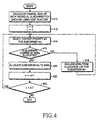
- FIG. 4 is a flowchart illustrating a resource allocation process according to the first embodiment of the present invention. It is assumed that the resource allocation process shown in FIG. 4 is performed after a BS completes collection of required data rate information from each MS.
- a BS calculates a channel gain of each sub-carrier for each MS using a cost function. After calculating the channel gain of each sub-carrier for each MS, the BS proceeds to step 412.
- the BS initializes an index k used for identifying an MS, and an index n used for identifying a sub-carrier. That is, the BS sets the indexes k and n to '0'. Thereafter, in step 414, the BS selects the highest-priority MS, i.e. an MS having the highest priority value, for an n th sub-carrier. It will be assumed herein that the highest-priority MS for the n th sub-carrier is an x th MS. The priority value is calculated using Equation (2) or Equation (5).
- the BS determines whether as many sub-carriers as the sub-carriers desired by the x th MS have already been allocated. If it is determined that as many sub-carriers as the sub-carriers desired by the x th MS have already been allocated, the BS excludes the x th MS from an allocation list for the n th sub-carrier in step 418, and then returns to step 414. However, if it is determined in step 416 that as many sub-carriers as the sub-carriers desired by the x th MS have not yet been allocated, the BS allocates the n th sub-carrier to the x th MS in step 420.
- the BS increases the index n by 1 to select the next sub-carrier.
- the BS determines whether a value of the index n is less than N, where N denotes the total number of sub-carriers. If it is determined that the value of the index n is less than N, the BS returns to step 414. However, if it is determined in step 424 that the value of the index n is not less than N (n ⁇ N), the BS ends the resource allocation process.
- the first embodiment of the present invention allocates resources taking into account a relative channel gain difference between MSs, thereby contributing to optimized resource allocation and minimized transmission power consumption.
- a second embodiment of the present invention is based on the fact that a low-pass loss MS generally has a low priority in the allocation process for most channels.
- the low-pass loss MS can be an MS located in the vicinity of a BS. Therefore, the second embodiment of the present invention preferentially allocates resources to MSs except for the low-pass loss MS, and then allocates the remaining resources to the low-pass loss MS.
- the second embodiment of the present invention prepares a scheme for calculating an MS priority value used for distinguishing a priority for each MS.
- the second embodiment designates at least one priority threshold, and preferentially allocates resources to the MS satisfying the priority threshold.
- Equation (6) r ( k ) denotes an MS priority value assigned to a k th MS.
- the MS priority value calculated by Equation (6) takes into account the data rate required by each MS and the average channel gain.
- the second embodiment can noticeably reduce the complexity by using 1-dimensional calculation expressed as the sum of the required data rate and the channel gain over all the sub-carriers.
- the MS having a lower average channel gain and a higher required data rate has a higher MS priority value r ( k ).
- the second embodiment determines a resource allocation priority of each MS based on the calculated MS priority value.
- the second embodiment allocates resources for each MS in order of the determined resource allocation priority.
- the resource allocation for each MS is performed based on a channel gain given for each sub-carrier. That is, the second embodiment allocates as many sub-carriers as the sub-carriers required by the MS in descending order of a sub-carrier having a high channel gain. If the desired sub-carriers have already been allocated to another MS, the second embodiment allocates sub-carriers having the second highest channel gain.
- the resource allocation method proposed by the second embodiment of the present invention is divided into a process of ordering a resource allocation order depending on the MS priority value, and a process of allocating sub-carriers for each MS in the resource allocation order.
- FIG. 5 is a flowchart illustrating a resource allocation process according to the second embodiment of the present invention. It is assumed that the resource allocation process shown in FIG. 5 is performed after a BS completes collection of required data rate information from each MS.
- a BS calculates an MS priority value for each MS using a cost function.
- the BS generates an MS list by ordering all MSs in descending order of the MS priority value.
- the BS selects an MS having the highest MS priority value among the MSs in the MS list. It is assumed herein that the MS having the highest MS priority value is an x th MS.
- step 516 the BS allocates the sub-carrier indicating the best channel state among its allocable sub-carriers, to the x th MS.
- step 518 the BS determines whether as many sub-carriers as the sub-carriers desired by the x th MS have already been allocated. If it is determined that as many sub-carriers as the sub-carriers desired by the x th MS have not yet been allocated, the BS returns to step 516.
- the BS excludes the x th MS from the MS list for the n th sub-carrier in step 520. Thereafter, in step 522, the BS determines whether there is any MS in the MS list. If it is determined that there is any MS in the MS list, the BS returns to step 514. However, if it is determined in step 522 that there is no MS in the MS list, the BS ends the resource allocation process.
- the second embodiment can also be implemented by assigning at least one priority threshold, classifying a resource allocation order into a plurality of sub-classes, and allocating resources for each sub-class.
- FIGs. 6A to 6C are diagrams illustrating simulation result data obtained through performance analysis according to the number of sub-classes. It is assumed in FIG. 6A that MSs are uniformly distributed over the entire cell. It is assumed in FIG. 6B that MSs are distributed only in a particular area of the cell. It is assumed in FIG. 6C that there is no pass loss difference between MSs. In addition, it is assumed that a ratio of voice service: video service: data service is 37:23:4 in the mobile communication system using 64 MSs and 512 sub-carriers.
- the resource allocation method proposed by the present invention shows constant performance regardless of the number of sub-classes.
- MSs are uniformly allocated in the cell.
- FIG. 6A it can be noted from FIG. 6A that it is possible to obtain a constant Signal-to-Noise Ratio (SNR) regardless of the number of priority thresholds used.
- SNR Signal-to-Noise Ratio
- FIG. 7 is a diagram illustrating a correlation between the number of sub-classes and the complexity. For the simulation of FIG. 7, it is assumed that a ratio of voice service: video service: data service is 37:23:4 in the mobile communication system using 64 MSs and 512 sub-carriers.
- the second embodiment of the present invention proposes the method for allocating resources for each MS using 1-dimensional calculation. Therefore, the resource allocation method proposed by the second embodiment of the present invention can noticeably reduce the complexity, compared with the existing cost function-based resource allocation method.
- the present invention allocates resources taking into account a relative channel gain difference between MSs, thereby contributing to optimized resource allocation and minimized transmission power consumption.
- the present invention allocates resources for each MS using 1-dimensional calculation. Therefore, the proposed resource allocation method can noticeably reduce the system complexity, compared with the existing cost function-based resource allocation method.
Landscapes
- Engineering & Computer Science (AREA)
- Computer Networks & Wireless Communication (AREA)
- Signal Processing (AREA)
- Mobile Radio Communication Systems (AREA)
Applications Claiming Priority (1)
| Application Number | Priority Date | Filing Date | Title |
|---|---|---|---|
| KR20050081470 | 2005-09-01 |
Publications (1)
| Publication Number | Publication Date |
|---|---|
| EP1760966A2 true EP1760966A2 (de) | 2007-03-07 |
Family
ID=37497861
Family Applications (1)
| Application Number | Title | Priority Date | Filing Date |
|---|---|---|---|
| EP06018354A Withdrawn EP1760966A2 (de) | 2005-09-01 | 2006-09-01 | Vorrichtung und Verfahren zur Ressourcenzuweisung in einem Mobilkommunikationssystem |
Country Status (4)
| Country | Link |
|---|---|
| US (1) | US20070058583A1 (de) |
| EP (1) | EP1760966A2 (de) |
| KR (1) | KR100744365B1 (de) |
| CN (1) | CN1968492A (de) |
Cited By (3)
| Publication number | Priority date | Publication date | Assignee | Title |
|---|---|---|---|---|
| CN102469463A (zh) * | 2010-11-04 | 2012-05-23 | 中兴通讯股份有限公司 | 一种边缘频率资源分配的方法、装置、系统及设备 |
| EP3478016A1 (de) * | 2017-10-27 | 2019-05-01 | Hewlett-Packard Enterprise Development LP | Bestimmung von kanalzuteilungsplanen |
| US11659588B1 (en) * | 2021-01-27 | 2023-05-23 | Amazon Technologies, Inc. | Multi-tier coordinated channel prioritization system |
Families Citing this family (17)
| Publication number | Priority date | Publication date | Assignee | Title |
|---|---|---|---|---|
| US8189621B2 (en) | 2006-05-12 | 2012-05-29 | Microsoft Corporation | Stack signaling to application with lack of requested bandwidth |
| JP2008072381A (ja) * | 2006-09-13 | 2008-03-27 | Toshiba Corp | 基地局、移動体通信システム、及びチャネル割当方法 |
| US8144793B2 (en) | 2006-12-12 | 2012-03-27 | Microsoft Corporation | Cognitive multi-user OFDMA |
| US7929623B2 (en) * | 2007-03-30 | 2011-04-19 | Microsoft Corporation | FEC in cognitive multi-user OFDMA |
| US7970085B2 (en) | 2007-05-08 | 2011-06-28 | Microsoft Corporation | OFDM transmission and reception for non-OFDMA signals |
| US8254328B2 (en) * | 2007-12-17 | 2012-08-28 | Nec Corporation | Scheduling method for multi-user MIMO in which resource blocks are allocated based on priorities |
| US8374130B2 (en) | 2008-01-25 | 2013-02-12 | Microsoft Corporation | Orthogonal frequency division multiple access with carrier sense |
| EP2139290B1 (de) * | 2008-06-19 | 2016-09-07 | Alcatel Lucent | Verfahren in einem drahtlosen Kommunikationsnetzwerk zur Ressourcenplanung und Planer für ein drahtloses Kommunikationsnetzwerk |
| CN101494490B (zh) * | 2009-01-04 | 2012-10-17 | 北京邮电大学 | 基于反馈的随机分布式自组织通信方法及系统 |
| US8923844B2 (en) * | 2009-08-14 | 2014-12-30 | Futurewei Technologies, Inc. | Coordinated beam forming and multi-user MIMO |
| US8594031B2 (en) * | 2009-10-09 | 2013-11-26 | Qualcomm Incorporated | Method and apparatus for providing quality of service for similar priority logical channels |
| CN101945482B (zh) * | 2010-09-21 | 2012-11-21 | 华为技术有限公司 | 一种用于多点协作CoMP方式的资源分配方法及基站 |
| CN102111890B (zh) * | 2011-02-22 | 2013-12-04 | 华为技术有限公司 | 一种优先级调整方法以及相关设备 |
| CN103907390A (zh) * | 2011-09-16 | 2014-07-02 | 诺基亚通信公司 | 用于无线电资源分配的方法和装置 |
| CN105745844B (zh) * | 2013-09-13 | 2019-03-01 | 慧与发展有限责任合伙企业 | 在子载波间重新分配功率的方法、无线发射器和存储介质 |
| CN105007629B (zh) * | 2015-03-16 | 2019-01-22 | 北京交通大学 | 超密集小小区网络系统中无线资源分配方法 |
| GB2575515A (en) * | 2018-07-13 | 2020-01-15 | Nec Corp | Communication system |
Family Cites Families (6)
| Publication number | Priority date | Publication date | Assignee | Title |
|---|---|---|---|---|
| US6157627A (en) | 1997-06-23 | 2000-12-05 | Telefonaktiebolaget Lm Ericsson | Channel allocation for mixed multislot services |
| JP4326700B2 (ja) | 1998-08-20 | 2009-09-09 | クゥアルコム・インコーポレイテッド | セルラ電話システム中の優先アクセスチャネル割当のためのシステムおよび方法 |
| KR100438173B1 (ko) | 2001-08-28 | 2004-07-01 | 엘지전자 주식회사 | 음성 처리 장비의 채널 상태 관리 방법 |
| US7412212B2 (en) * | 2002-10-07 | 2008-08-12 | Nokia Corporation | Communication system |
| US7257407B2 (en) * | 2003-03-26 | 2007-08-14 | Sony Corporation | System and method for dynamically allocating data rates and channels to clients in a wireless network |
| KR20060038786A (ko) | 2004-11-01 | 2006-05-04 | 삼성전자주식회사 | 무선 접속 프로토콜에서 물리 계층과 매체 접근 제어계층간에 자원을 할당하는 시스템 및 방법 |
-
2006
- 2006-09-01 EP EP06018354A patent/EP1760966A2/de not_active Withdrawn
- 2006-09-01 KR KR1020060084350A patent/KR100744365B1/ko not_active Expired - Fee Related
- 2006-09-01 CN CNA2006101635854A patent/CN1968492A/zh active Pending
- 2006-09-01 US US11/514,450 patent/US20070058583A1/en not_active Abandoned
Cited By (8)
| Publication number | Priority date | Publication date | Assignee | Title |
|---|---|---|---|---|
| CN102469463A (zh) * | 2010-11-04 | 2012-05-23 | 中兴通讯股份有限公司 | 一种边缘频率资源分配的方法、装置、系统及设备 |
| CN102469463B (zh) * | 2010-11-04 | 2014-06-11 | 中兴通讯股份有限公司 | 一种边缘频率资源分配的方法及其装置 |
| EP3478016A1 (de) * | 2017-10-27 | 2019-05-01 | Hewlett-Packard Enterprise Development LP | Bestimmung von kanalzuteilungsplanen |
| CN109729531A (zh) * | 2017-10-27 | 2019-05-07 | 慧与发展有限责任合伙企业 | 确定信道规划 |
| US10477412B2 (en) | 2017-10-27 | 2019-11-12 | Hewlett Packard Enterprise Development Lp | Determine channel plans |
| US11153764B2 (en) | 2017-10-27 | 2021-10-19 | Hewlett Packard Enterprise Development Lp | Determine channel plans |
| CN109729531B (zh) * | 2017-10-27 | 2022-05-27 | 慧与发展有限责任合伙企业 | 确定信道规划 |
| US11659588B1 (en) * | 2021-01-27 | 2023-05-23 | Amazon Technologies, Inc. | Multi-tier coordinated channel prioritization system |
Also Published As
| Publication number | Publication date |
|---|---|
| KR20070026244A (ko) | 2007-03-08 |
| US20070058583A1 (en) | 2007-03-15 |
| CN1968492A (zh) | 2007-05-23 |
| KR100744365B1 (ko) | 2007-07-30 |
Similar Documents
| Publication | Publication Date | Title |
|---|---|---|
| EP1760966A2 (de) | Vorrichtung und Verfahren zur Ressourcenzuweisung in einem Mobilkommunikationssystem | |
| EP2070263B1 (de) | Verfahren zur ressourcenzuweisung in einem drahtlosen kommunikationssystem | |
| EP1610573B1 (de) | Verfahren zum Zuweisen von Ressourcen in einem Mehrträgerkommunikationssystem | |
| KR101020044B1 (ko) | 다중 주파수 대역을 사용하는 통신 시스템의 대역 할당 스케쥴링 장치 및 방법 | |
| US20120198077A1 (en) | Resource allocation method and device in communication network | |
| US7804805B2 (en) | Apparatus and method for scheduling transmission of data packets in a multichannel wireless communication system | |
| US8077678B2 (en) | Radio resource allocating method and apparatus in adaptive antenna system | |
| KR101627164B1 (ko) | 다중 주파수 시스템에서 자원 할당을 위한 장치 및 방법 | |
| US7373151B1 (en) | Distributed dynamic channel allocation technique for multi-carrier CDMA cellular systems with mobile base stations | |
| US8442540B2 (en) | Method for allocating resources | |
| US8477700B2 (en) | Method and arrangement for resource allocation | |
| EP1946577B1 (de) | Auswahl von funkbetriebsmitteln in einem funkkommunikationsnetz | |
| CN101227695A (zh) | 一种小区通信资源分配方法与装置 | |
| US8219104B2 (en) | Radio resource allocation which optimizes system throughput using a small amount of computation | |
| US9681454B2 (en) | Uplink scheduler algorithm for orthogonal division multiple access systems | |
| KR101335363B1 (ko) | 무선 통신 시스템에서 주파수 할당 방법 | |
| US20090290548A1 (en) | Apparatus and method for managing wireless resources | |
| CN100450198C (zh) | 一种多时隙分组无线资源分配方法 | |
| US8526307B2 (en) | Proportional-fair radio resource management | |
| EP1740006A1 (de) | Verfahren zur dynamischen Kanalzuteilung in einem OFDMA Mobilkommunikationssystem | |
| US7924777B2 (en) | Method for deciding transmission priority of non-realtime data and apparatus and method for controlling interference between cells using the same | |
| KR20060136291A (ko) | 직교주파수분할 다중접속 이동통신시스템에서 동적 채널할당방법 | |
| KR101017426B1 (ko) | 직교주파수분할다중접속 시스템을 위한 모드 선택 기반 채널 피드백 감소 방법 | |
| KR101132620B1 (ko) | 직교 주파수 분할 다중 액세스 시스템에서의 스케줄링 장치 및 방법 | |
| CN118741703A (zh) | 载波聚合非对称预测载波指示与分配方法和装置 |
Legal Events
| Date | Code | Title | Description |
|---|---|---|---|
| PUAI | Public reference made under article 153(3) epc to a published international application that has entered the european phase |
Free format text: ORIGINAL CODE: 0009012 |
|
| 17P | Request for examination filed |
Effective date: 20060901 |
|
| AK | Designated contracting states |
Kind code of ref document: A2 Designated state(s): AT BE BG CH CY CZ DE DK EE ES FI FR GB GR HU IE IS IT LI LT LU LV MC NL PL PT RO SE SI SK TR |
|
| AX | Request for extension of the european patent |
Extension state: AL BA HR MK YU |
|
| STAA | Information on the status of an ep patent application or granted ep patent |
Free format text: STATUS: THE APPLICATION HAS BEEN WITHDRAWN |
|
| 18W | Application withdrawn |
Effective date: 20090330 |