EP1761075A2 - Stereoskopische Anzeigevorrichtung und zugehörige Steuerungsverfahren - Google Patents
Stereoskopische Anzeigevorrichtung und zugehörige Steuerungsverfahren Download PDFInfo
- Publication number
- EP1761075A2 EP1761075A2 EP06118666A EP06118666A EP1761075A2 EP 1761075 A2 EP1761075 A2 EP 1761075A2 EP 06118666 A EP06118666 A EP 06118666A EP 06118666 A EP06118666 A EP 06118666A EP 1761075 A2 EP1761075 A2 EP 1761075A2
- Authority
- EP
- European Patent Office
- Prior art keywords
- image
- display
- images
- display device
- stereoscopic
- Prior art date
- Legal status (The legal status is an assumption and is not a legal conclusion. Google has not performed a legal analysis and makes no representation as to the accuracy of the status listed.)
- Withdrawn
Links
Images


Classifications
-
- H—ELECTRICITY
- H04—ELECTRIC COMMUNICATION TECHNIQUE
- H04N—PICTORIAL COMMUNICATION, e.g. TELEVISION
- H04N13/00—Stereoscopic video systems; Multi-view video systems; Details thereof
- H04N13/10—Processing, recording or transmission of stereoscopic or multi-view image signals
- H04N13/194—Transmission of image signals
-
- H—ELECTRICITY
- H04—ELECTRIC COMMUNICATION TECHNIQUE
- H04N—PICTORIAL COMMUNICATION, e.g. TELEVISION
- H04N13/00—Stereoscopic video systems; Multi-view video systems; Details thereof
- H04N13/10—Processing, recording or transmission of stereoscopic or multi-view image signals
- H04N13/106—Processing image signals
- H04N13/172—Processing image signals image signals comprising non-image signal components, e.g. headers or format information
- H04N13/178—Metadata, e.g. disparity information
-
- H—ELECTRICITY
- H04—ELECTRIC COMMUNICATION TECHNIQUE
- H04N—PICTORIAL COMMUNICATION, e.g. TELEVISION
- H04N13/00—Stereoscopic video systems; Multi-view video systems; Details thereof
- H04N13/20—Image signal generators
- H04N13/204—Image signal generators using stereoscopic image cameras
- H04N13/239—Image signal generators using stereoscopic image cameras using two two-dimensional [2D] image sensors having a relative position equal to or related to the interocular distance
-
- H—ELECTRICITY
- H04—ELECTRIC COMMUNICATION TECHNIQUE
- H04N—PICTORIAL COMMUNICATION, e.g. TELEVISION
- H04N13/00—Stereoscopic video systems; Multi-view video systems; Details thereof
- H04N13/30—Image reproducers
-
- H—ELECTRICITY
- H04—ELECTRIC COMMUNICATION TECHNIQUE
- H04N—PICTORIAL COMMUNICATION, e.g. TELEVISION
- H04N13/00—Stereoscopic video systems; Multi-view video systems; Details thereof
- H04N13/30—Image reproducers
- H04N13/332—Displays for viewing with the aid of special glasses or head-mounted displays [HMD]
- H04N13/344—Displays for viewing with the aid of special glasses or head-mounted displays [HMD] with head-mounted left-right displays
-
- H—ELECTRICITY
- H04—ELECTRIC COMMUNICATION TECHNIQUE
- H04N—PICTORIAL COMMUNICATION, e.g. TELEVISION
- H04N13/00—Stereoscopic video systems; Multi-view video systems; Details thereof
- H04N13/30—Image reproducers
- H04N13/398—Synchronisation thereof; Control thereof
-
- H—ELECTRICITY
- H04—ELECTRIC COMMUNICATION TECHNIQUE
- H04N—PICTORIAL COMMUNICATION, e.g. TELEVISION
- H04N13/00—Stereoscopic video systems; Multi-view video systems; Details thereof
- H04N13/10—Processing, recording or transmission of stereoscopic or multi-view image signals
- H04N13/106—Processing image signals
- H04N13/15—Processing image signals for colour aspects of image signals
-
- H—ELECTRICITY
- H04—ELECTRIC COMMUNICATION TECHNIQUE
- H04N—PICTORIAL COMMUNICATION, e.g. TELEVISION
- H04N13/00—Stereoscopic video systems; Multi-view video systems; Details thereof
- H04N13/10—Processing, recording or transmission of stereoscopic or multi-view image signals
- H04N13/106—Processing image signals
- H04N13/156—Mixing image signals
Definitions
- the present invention relates to a stereoscopic display device and control method therefor, and more particularly, to a head-mounted type stereoscopic display device and control method therefor.
- a stereoscopic video see-through HMD Head Mounted Display
- a stereoscopic video see-through HMD is a device that displays stereoscopic images in front of the eyes of the wearer.
- composite images in which three-dimensional virtual images seen from the viewpoint position of the wearer are superimposed on stereoscopic video images that are substantially the same as those seen when the user is not wearing the HMD, are generated and presented to the HMD, the wearer experiences a feeling just like that in which virtual objects appear to be present in real space. That is Mixed Reality.
- CG Computer Graphics
- stereoscopic video images are usually sensed by a stereoscopic video camera attached to the HMD.
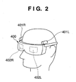
- FIG. 2 is a schematic diagram showing a state of attachment of a stereoscopic video see-through HMD 400.
- the video see-through HMD 400 has the external appearance of eyeglasses or goggles, inside of which a display device for the right eye 402R and a display device for the left eye 402L, composed for example of LCDs, are disposed.
- a display device for the right eye 402R and a display device for the left eye 402L, composed for example of LCDs are disposed.
- stereoscopic video images are acquired by video cameras attached to the HMD, for example, stereoscopic video cameras 401R, 401L are mounted at positions near the viewpoint position of the wearer.
- the present invention is conceived in light of the above-described problems of the conventional art.
- a stereoscopic display device that performs stereoscopic display by displaying images for display on a display device for right eye and a display device for left eye, respectively, characterized by comprising: receiving means for receiving a stereoscopic image composed of a pair of images for display; identification means for identifying each image of the pair of images for display as either a display image for the right eye or a display image for the left eye; output means for taking the pair of images for display as input and for outputting one of the pair of images to the display device for the right eye and the other of the pair of images to the display device for the left eye; and control means for controlling the output means so that, based on results of identification by the identification means, an image for display determined to be the image for display for the right eye is output to the display device for the right eye and an image for display determined to be the image for display for the left eye is output to the display device for the left eye.
- a control method for a stereoscopic display device having output means capable of taking a pair of images for display as input and outputting one such image to a display device for the right eye and the other such image to a display device for the left eye characterized by comprising: a receiving step of receiving a stereoscopic image composed of a pair of images for display; an identification step of identifying each image of the pair of images for display as either a display image for the right eye or a display image for the left eye; and a control step of controlling the output means so that, based on results of identification in the identification step and the current input-output relation of the output means, an image for display determined to be the image for display for the right eye is output to the display device for the right eye and an image for display determined to be the image for display for the left eye is output to the display device for the left eye.
- the stereoscopic display device of the present invention enables the user to connect the image input cable without concern for whether the image signals are for the right eye or for the left eye.
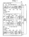
- FIG. 1 is a block diagram showing an example of the structure of a mixed reality presenting system according to a first embodiment of the present invention
- FIG. 2 is a schematic diagram showing the state of attachment of a stereoscopic video see-through HMD
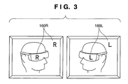
- FIG. 3 is a diagram showing an example in which information representing an image for the left eye and information representing an image for the right eye is added as information in which the left and right images can be distinguished to sensed image data generated by image sensing units 110R, 110L as electronic watermark images 160R, 160L;
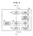
- FIG. 4 is a block diagram showing an exemplary configuration of an image processing unit 200' in a mixed reality presenting system according to a second embodiment of the present invention
- FIG. 5 is a block diagram showing an exemplary configuration of a mixed reality presenting system according to a third embodiment of the present invention.
- FIG. 6 is a flow chart showing sensed image data processing in a video see-through HMD according to the embodiments
- FIG. 7 is a flow chart showing image display processing in a video see-through HMD according to the embodiments.
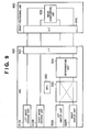
- FIG. 8 is a block diagram showing an exemplary configuration of an image processing unit 200 in the mixed reality presenting system according to the first embodiment of the present invention
- FIG. 9 is a block diagram showing an exemplary configuration of a mixed reality presenting system according to a fifth embodiment of the present invention.
- FIG. 10 is a flow chart illustrating an image sensing process during a connection determination process in the mixed reality presenting system according to the fifth embodiment of the present invention.
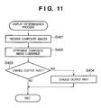
- FIG. 11 is a flow chart illustrating processing performed by a determination unit in the mixed reality presenting system according to the fifth embodiment of the present invention.
- FIG. 12 is a flow chart illustrating another example of a connection determination process in the mixed reality presenting system according to the fifth embodiment of the present invention.
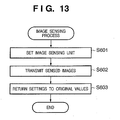
- FIG. 13 is a flow chart illustrating is a flow chart illustrating an image sensing process during a connection determination process in a mixed reality presenting system according to a sixth embodiment of the present invention.
- FIG. 14 is a flow chart illustrating processing performed by a determination unit in the mixed reality presenting system according to the sixth embodiment of the present invention.
- FIG. 15 is a flow chart illustrating processing performed by a determination unit in a mixed reality presenting system according to a seventh embodiment of the present invention.
- FIG. 16 is a block diagram showing an exemplary configuration of a mixed reality presenting system according to an eighth embodiment of the present invention.
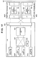
- FIG. 17 is a block diagram showing a state in which left and right display cables are connected in reverse in the configuration shown in FIG. 16;
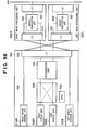
- FIG. 18 is a block diagram showing a state in which left and right sensing unit cables are connected in reverse in the configuration shown in FIG. 16;
- FIG. 19 is a block diagram showing a state in which both left and right image sensing and display cables are connected in reverse in the configuration shown in FIG. 16;
- FIG. 20 is a flow chart illustrating a process performed by the image processing units 600R and 600L of determining whether sensed images received are for the left eye or for the right eye in the mixed reality presenting system according to the eighth embodiment of the present invention.
- FIG. 1 is a block diagram showing an example of the structure of a mixed reality presenting system according to a first embodiment of the present invention.
- the mixed reality presenting system comprises a head-mounted type image-sensing and displaying device (hereinafter referred to as a video see-through HMD or simply as HMD) 100 and an image processing unit 200.
- a head-mounted type image-sensing and displaying device hereinafter referred to as a video see-through HMD or simply as HMD
- an image processing unit 200 hereinafter referred to as a video see-through HMD or simply as HMD
- the video see-through HMD 100 comprises a right image sensing unit 110R, a left image sensing unit 110L, an image information identification unit 130, a right display unit 120R, a left display unit 120L and an MPU 140.
- an image sensing device 111R is a CCD image sensor, a CMOS image sensor or the like, which converts images into electrical signals.
- a timing generator (hereinafter referred to as TG) 116R generates signals that drive the image sensing device 111R.
- a V-Dr (V driver) 117R receives the signals from the TG 116R and generates signals that carry out control in the vertical direction of the image sensing device 111R.
- a CDS/AGC unit 112R performs CDS (Correlation Double Sampling) and gain adjustment on the analog signals output from the image sensing device 111R.
- An AD converter 113R converts the analog signals that the CDS/AGC unit 112R outputs into digital signals.
- a digital signal processor 114R performs gain control, color control, luminance control and gamma correction on the digital signals that the AD converter 113R outputs, and outputs sensed image signals.
- a sensed image output unit 115R converts the sensed image signals into a data format suitable for transmission over a digital interface such as a USB or an IEEE 1394, and outputs the formatted data to the image processing unit 200.
- the structure and the operation of the left image sensing unit 110L is exactly the same as that of the right image sensing unit 110R.
- the right image sensing unit 110R and the left image sensing unit 110L may be implemented by, for example, compact video cameras.
- the right image sensing unit 110R and the left image sensing unit 110L as shown as stereoscopic video cameras 401R, 401L in FIG. 2, are fixedly mounted at portions of the HMD 400 in the vicinity of both eyes of the wearer (observer) so as to face in the same direction as the line of sight of the observer when the HMD is worn correctly.
- the real space images sensed by the right and left image sensing units 110R, 110L are input to the image processing unit 200 through cables (also referred to as sensing unit cables) 151R, 151L.
- the image information identification unit 130 receives through cables (also referred to as display cables) 153, 154 composite images for the left eye and composite images for the right eye that are pairs of images for display generated by the image processing unit 200.
- the image information identification unit 130 comprises display image input units 131R, 131L and a switcher 132.
- the switcher 132 is a two-input/two-output matrix switch, the inputs of which are the composite images output by the image input units 131R, 131L and to the outputs of which are connected the right display unit 120R and the left display unit 120L.
- the display image input units 131R, 131L identify information for distinguishing between left and right display images contained in the composite images and notify the results to the MPU 140.
- the MPU 140 switches the connections between the inputs and the outputs of the switcher 132 as necessary so that the composite images for the right eye are output to the right display unit 120R and the composite images for the left eye are output to the left display unit 120L.
- the right display unit 120R comprises a display device for the right eye 121R and a display drive unit 122R for driving the display device 121R.
- the left display unit 120L comprises a display device for the left eye 121L and a display drive unit 122L for driving the display device 121L.
- the display devices 121R, 121L are compact, lightweight display devices such as LCD displays, organic EL displays or the like.
- the MPU 140 is a microprocessor equipped with, for example, a CPU, a ROM that stores a control program for the CPU, and a RAM used as the CPU work area. By the CPU executing the control program stored in the ROM, the MPU 140 controls each part of the video see-through HMD and implements a variety of operations described later.
- FIG. 8 is a block diagram showing an exemplary configuration of the image processing unit of the present embodiment.
- An image input unit 402 which is a digital interface adapted for sensed image output units 115R, L, receives sensed images from the image sensing units 110R, L and supplies them to an image composition unit 407 and a marker detection unit 403.
- the marker detection unit 403 detects, for example, two-dimensional markers placed in real space in advance.
- the two-dimensional markers are indexes whose absolute positions within real space are already known and which have characteristics (color, shape, pattern and so forth) that can be extracted from the sensed images. Therefore, the marker detection unit 403 detects the two-dimensional markers by searching for areas that match the characteristics of the two-dimensional markers from among the images.
- a viewpoint position and orientation calculation unit 404 calculates the three-dimensional position and orientation of the HMD 100 using marker information detected by the marker detection unit 403 (such as the positions within the image, the orientation and surface areas of the markers) as well as the position in the marker coordinate system of the marker characteristic points and the camera parameters of the image sensing unit 110.
- marker information detected by the marker detection unit 403 such as the positions within the image, the orientation and surface areas of the markers
- the position and orientation calculation technology is well known within that technical field and moreover is not directly related to the present invention, and thus a detailed description thereof shall be omitted here.
- a virtual space database 406 is, for example, a hard disk drive, and contains virtual object three-dimensional CG model data.
- an image generation unit 405 Based on the virtual object three-dimensional CG model data stored in the virtual space database 406 and the HMD 400 position and orientation data calculated by the viewpoint position and orientation calculation unit 404, an image generation unit 405 generates the three-dimensional CG images that should be observed from the viewpoints of the left eye and the right eye of the observer and supplies the generated CG images to the image composition unit 407.
- geometric data on the CG models contained in the virtual space database 406, attribute information such as color and texture, and lighting information are used. It should be noted that the generation of three-dimensional CG images is a known art, and therefore a detailed discussion thereof shall be omitted here.
- the image composition unit 407 combines sensed images from the image input unit 402 and CG images (images of virtual objects) from the image generation unit 405 and generates a composite image for the right eye and a composite image for the left eye.
- An image output unit 408 is for example a DVI interface or other such display interface, and outputs the composite images for the right eye and the composite images for the left eye output by the image composition unit 407 to the image information identification unit 130 through cables 153, 154.
- this type of image processing unit 200 can be implemented by an ordinary commercially available computer device. Therefore, at least a portion of the processing that takes place inside the image processing unit 200 described below can be implemented as software by the CPU executing the control program.
- a step S101 the process begins with the sensing of parallax images of real space.
- the HMD 100 is mounted so that the image sensing units 110R, L are positioned near the viewpoint (pupil) position of the wearer when the HMD 100 is worn correctly. Therefore, the image sensing devices 111R, 111L of the image sensing units 110R, 110L sense images that substantially the same images as those observed from the pupil positions of the wearer of the HMD 100, that is, parallax images that differ only by the length of a baseline that corresponds to the left and right pupil positions.
- the object images sensed by the image sensing devices 111R, 111L are input as analog signals to respective CDS/AGC units 112R, 112L, where such processes as CDS (Correlation Double Sampling) and gain adjustment are performed. Thereafter, the analog signals thus processed are converted into digital signals at the AD converters 113R, 113L (step S102).
- CDS Correlation Double Sampling
- the sensed image signals converted into digital signals at the AD converters 113R, 113L are input to the digital signal processors 114R, 114L, gain control, color control, luminance control and gamma correction are performed, and sensed image data is generated (step S103).
- the digital signal processors 114R, 114L add additional information, in the form, for example, of an invisible electronic watermark, to each frame of the left and right sensed image data generated in step S103.
- This additional information is composed of information that at least enables left and right images to be distinguished from each other (information that represents the directionality of the image) (step S104).
- HMD-specific information such as image sensing lens information and shutter speed as well as photographer information, can also be included in the additional information.
- FIG. 3 is a diagram showing an example in which electronic watermark images (160R, 160L), representing information representing an image for the right eye and information representing an image for the left eye, are added to the sensed image data generated by the image sensing units 110R, 110L as information that enables the left and right images to be distinguished.
- electronic watermark images 160R, 160L
- FIG. 3 examples are shown of visible electronic watermark images, such information may be embedded in the sensed image data as invisible electronic watermark images as well.
- such information may also be embedded in the sensed image data not in the form of images but of code information.
- information enabling left and right images to be distinguished may be added not as electronic watermarks but instead as a portion of such commonly used additional information as image data header information.
- information may be added to a single dot at the edge of the image, or information may be added to an area that is not displayed.
- a step S105 the sensed image data with the embedded electronic watermarks is output to the image processing unit 200 through the sensed image output units 115R, 115L and the sensing unit cables 151R, 151L.
- the composition process described above is performed without regard to the embedded electronic watermarks, generating a composite image for the right eye and a composite image for the left eye. These images are then output to the image information identification unit 130 through the image output unit 408 and the display cables 153, 154.
- FIG. 7 is a flow chart illustrating the operation of the image information identification unit of the HMD 100.
- the image information identification unit 130 receives a composite image for the right eye and a composite image for the left eye at the display image input units 131R, 131L from the image processing unit 200 over the cables 153, 154. At this stage, the image information identification unit 130 does not know which of the two composite images received is the one for the right eye and which is the one for the left eye. Then, at a step S202, from the received composite images, the display image input units 131R, 131L extract the additional information indicating which image is for the left eye and which image is for the right eye and identify that additional information. The results of that identification are reported to the MPU 140.
- the MPU 140 based on the results of that identification, switches the connections between the input and the output of the switcher 132 as necessary so that the composite image for the right eye is output to the right display unit 120R and the composite image for the left eye is output to the left display unit 120L.
- the MPU 140 receives the results of the identification performed by the display image input units 131R, 131L, and in a step S204 determines whether or not it is necessary to change the relation between the connections of the switcher 132 from the relation between the connections of the switcher 132 at the time the results of the identification are received and from the results of the identification (step S203).
- the MPU 140 determines that a change is not necessary and the process returns to step S201.
- the MPU 140 determines that the inputs are reversed, then in step S204 it reverses the relations between the connections of the switcher 132, and the process returns to step S201.
- the present embodiment provides, in a head-mounted type display device having a display device for the right eye and a display device for the left eye, a switch capable of changing the connections between the pair of images for display and the pair of display devices. Then, by identifying the directionality of received images for display and switching the connections between the switches depending on the results of that identification, the present embodiment eliminates the need to be conscious of that directionality when connecting the cables for inputting the composite images to the HMD, therefore simplifying connection between the HMD and the devices that supply the HMD with images for display.
- the display image input units 131R, 131L need not make an identification of all the frames in which additional information is detected and report the results of that determination to the MPU 140.
- matters may be arranged so that the display image input units 131R, 131L only report the results of their determinations at each predetermined time interval or at every predetermined frames, or the most recent identification results are retained and the MPU 140 notified only when there has been a change.
- matters may be arranged so that, whenever additional information indicating that a given image is either a left-eye image or a right-eye image is embedded as invisible information, the display image input units 131R, 131L add that information as visible information to the composite images.
- the display image input units 131R, 131L add that information as visible information to the composite images.
- the MPU 140 determines the necessity of a change in the connections of the switcher 132 and controls switching, alternatively, matters may be arranged so that one or the other of the display image input units 131R, 131L performs switching.
- image sensing units 110R, 110L may also be constituted as separate units from the HMD.
- FIG. 4 is a block diagram showing an exemplary configuration of an image processing unit 200' in a mixed reality presenting system according to a second embodiment of the present invention.
- additional information is composed in an image composition unit 407' of the image processing unit 200', without composing additional information representing left and right images in the right image sensing unit 110R and the left image sensing unit 110L.
- the additional information to be composed is stored in an additional information storage unit 409.
- the image composition unit 407' adds additional information indicating that the image is for the right eye to images input from the right image sensing unit 110R, and adds information indicating that the image is for the left eye to images input from the left image sensing unit 110L.
- the additional information can be added as an electronic watermark image or added as header information.
- HMD-specific information such as image sensing lens information and shutter speed as well as photographer information, can also be included in the additional information.
- this embodiment can also be adapted to a mixed reality presenting system that uses an image sensing unit that does not have the ability to add additional information.
- composition of virtual object images and additional information for left and right sensed images are executed using a single image processing unit.
- the number of image processing units is increased to two, each dedicated to either an image for the right eye or an image for the left eye, respectively, enabling processing speed to be increased.
- FIG. 5 is a block diagram showing an exemplary configuration of a mixed reality presenting system according to the present embodiment. Adopting a configuration of this type enables the composition of virtual object images and the combination of virtual object images and additional information to be processed at high speed.
- a mechanism that is the equivalent of the image information identification unit 130 may be added to the image processing unit. Specifically, a structure that is the equivalent of the image information identification unit 130 is added to the first stage of the image input unit 402 and the relation between the connections of the switcher 132 are controlled so that the input images from the image sensing units 110R, 110L and the left-right relations in the input of the image input unit 402 are correct.
- the determination of necessity of switching the connections and switching control may be carried out by a control unit of the image processing unit or by the display image input units 131 inside the image information identification unit 130.
- composition of virtual object images is such that correct composite images cannot be obtained unless the virtual images are added to sensed images correctly characterized as to left and right, it is necessary that the right and left sensed images be input correctly to the processing system for the image for the right eye and the processing system for the image for the left eye. Therefore, in cases in which there is a possibility of mistaking the connections between image sensing units 110R, 110L, the configuration of the present embodiment is useful.
- the cable connections are determined by embedding additional information in the sensed images, and the display image for the right eye is displayed on the display device for the right eye and the display image for the left eye is displayed on the display device for the left eye.
- FIG. 9 is a block diagram showing an exemplary configuration of a mixed reality presenting system according to the present embodiment.
- the mixed reality presenting system is composed of an HMD 500 and an image processing unit 600.
- a left image sensing unit 510L and a right image sensing unit 510R sense images that are displayed respectively on a left display unit 520L and a right display unit 520R of the HMD.
- the left display unit 520L and the right display unit 520R display composite images (for the left eye and for the right eye) composed of sensed images and CG images supplied from the image processing unit 600.
- a transceiver I/F 550 is an interface for sending and receiving images and signals to and from the image processing unit 600.
- a determination unit 540 identifies the received composite images.
- a switcher 530 determines the display unit that will display the received composite image.
- An MPU 560 is a microprocessor having, for example, a CPU, a ROM that stores a control program for the CPU, and a RAM used as the CPU work area.
- the image processing unit 600 is composed of, for example, a personal computer (PC), a work station, or the like.
- a transceiver I/F 610 is an interface that receives sensed image signals and data signals from the HMD 500 and sends composite image signals and data signals to the HMD 500.
- An image composition unit 620 superimposes CG images on the sensed images received at the transceiver I/F 610 and generates composite images that it then sends to the HMD 500 through the transceiver I/F 610.
- the MPU 560 controls the left and right image sensing units 510L, 510R and changes the luminance of the sensed images. For example, by controlling the shutter speed and/or gain value of the left and right image sensing units 510L, 510R, the luminance of the sensed images can be changed.
- the MPU 560 sends the left and right sensed images obtained as a result of changing the luminance to the image processing unit 600 using the transceiver I/F 550. Thereafter, the MPU 560, in a step S303, returns the image sensing unit 510L, 510R settings to their original values, and relinquishes control of the luminance of the sensed images.
- the luminance of the sensed images may be changed for either both or only one of the image sensing units 510L, 510R.
- the luminance of the sensed images may be different for the left and the right image sensing units 510L, 510R.
- FIG. 11 is a flow chart illustrating the operation of the determination unit 540.
- the determination unit 540 receives two sensed images from the image processing unit 600 through the transceiver I/F 550. In a step S402, the determination unit 540 determines the luminance of the sensed images received. As described above, the MPU 560 controls the left and right image sensing units 510L, 510R and changes the luminance of the sensed images in advance. As a result, the determination unit 540 can predict the luminance of the sensed images to be received.
- the MPU 560 is shown as raising the luminance of the sensed image for the left image sensing unit 510L and lowering the luminance of the right image sensing unit 510R.
- the determination unit 540 can predict that, of the two sensed images to be received from the image processing unit, the luminance value of the sensed image for the left eye will be higher and the luminance value of the sensed image for the right eye will be lower.
- step S402 by comparing the.luminance of the two sensed images received, the determination unit 540 determines which of the sensed images received is for the right eye and which is for the left eye.
- the determination unit 540 assesses the necessity of an output path change. If in the current state of the switcher 530 the composite image for the left eye is input to the left display unit 520L and the composite image for the right eye is input to the right display unit 520R, then there is no need for an output path change. If the left-right relation between the composite images and the display units is reversed, then there is a need for an output path change.
- a step S404 the determination unit 540 requests that the MPU 560 change the output path, and the MPU 560 switches the connections between the input and the output of the switcher 530.
- the present embodiment also enables the composite images for the left eye to be displayed correctly on the left display unit and the composite images for the right eye to be displayed correctly on the right display unit.
- the assessment of the necessity of an output path change based on one pair of composite images may be determined based on the results of assessments for a plurality of sets of composite images.
- FIG. 12 is a flow chart illustrating processing in a case in which the assessment process is carried out multiple times.
- steps that perform the same processes as the process steps described in FIG. 10 and FIG. 11 are assigned the same reference numerals.
- step S301 the MPU 560 controls the left and right image sensing units 510L, 510R and changes the luminance of the sensed images.
- step S402 the determination unit 540 identifies left and right for the composite images received from measuring the luminance of one set of composite images received or the like.
- step S503 it is determined whether or not the number of identifications made has reached a preset number of times (N times), and if N times is not reached then the number of times the identification is made is increased by one (step S504). If in step S503 the number of times the determination is made has reached N times, then in step S303 the MPU 560 returns the image sensing units 510L, 510R to their original settings.
- step S403 an assessment is made of the necessity of an output path change. For example, as a result of the determination of left and right based on luminance made in step S402, the assessment of the necessity of an output path change can be made on the basis of determination results obtained with a high degree of probability.
- step S404 the output path is changed.
- connection determination process there is no particular limitation on the timing with which the above-described connection determination process is performed, and accordingly, such process can be performed when the HMD 500 is activated, when the system is activated, or on the basis of user operation or the like at an arbitrary timing.
- the images for display may be prevented from being displayed by turning the power to the display units 520L, 520R OFF.
- path control is performed with the switcher 530 disposed in front of the display units 520L, 520R.
- it is also possible to carry out the same control by disposing the switcher 530 between the image sensing units 510L, 510R and the transceiver I/F 550.
- the image sensing units 510L, 510R are controlled by the MPU 560 of the HMD 500
- the image sensing units 510L, 510R may be controlled from the image processing unit 600.
- the extent of the change in the luminance can be performed at a predetermined value or at a value that is determined by communication at an arbitrary timing between the HMD 500 and the image processing unit 600.
- the connections are determined not by embedding additional information in the sensed images but by changing the luminance of the sensed images themselves.
- the circuits and processes needed to embed the additional information in the sensed images become unnecessary, enabling device cost and processing load to be reduced.
- a description is given of a configuration that determines the cable connections by changing the luminance of the sensed images.
- a description is given of a configuration that makes the same determination not by changing the luminance of the sensed images but by changing the color of the sensed images. It should be noted that this embodiment can also be adapted to the mixed reality presenting system described in the fifth embodiment, and therefore a description is given of the contents of the processing using the same configuration as that of the fifth embodiment.
- the MPU 560 controls the left and right image sensing units 510L, 510R so as to change the color of the sensed images. For example, by controlling the white balance of the left and right image sensing units 510L, 510R, the color of the sensed images can be changed. For example, the MPU 560 controls the left image sensing unit 510L white balance so as to emphasize red and to de-emphasize blue and green. In addition, MPU 560 controls the right image sensing unit 510R white balance to emphasize blue and to de-emphasize red and green.
- the MPU 560 sends left and right sensed images obtained by changing the color to the image processing unit 600 using the transceiver I/F 550. Thereafter, the MPU 560, in a step S603, returns the settings of the image sensing units 510L, 510R to their original values and relinquishes control over the luminance of the sensed images.
- the color of the sensed images may be changed for either both or only one of the image sensing units 510L, 510R.
- the color of the sensed images may be different for the left and the right image sensing units 510L, 510R.
- FIG. 14 is a flow chart illustrating the operation of the determination unit 540 of the present embodiment.
- the determination unit 540 receives two composite images from the image processing unit 600 through the transceiver I/F 550. In a step S702, the determination unit 540 determines the color of the composite images received. As described above, the MPU 560 controls the left and right image sensing units 510L, 510R and changes the color of the sensed images in advance. As a result, the determination unit 540 can predict the color of the composite images to be received.
- step S601 in FIG. 13 assume that the MPU 560 controls each of the image sensing units 510L, 510R so as to emphasize red and de-emphasize blue and green in the sensed images of the left image sensing unit 510L and to emphasize blue and de-emphasize red and green in the sensed images of the right image sensing unit 510R, respectively.
- the determination unit 540 can predict that, of the two composite images received from the image processing unit 600, the composite image for the left eye will be reddish and the composite image for the right eye will be bluish.
- step S702 by comparing the colors of the two composite images received, the determination unit 540 determines which of the composite images received is for the right eye and which is for the left eye.
- the determination unit 540 assesses the necessity of an output path change. If in the current state of the switcher 530 the composite image for the left eye is input to the left display unit 520L and the composite image for the right eye is input to the right display unit 520R, then there is no need for an output path change. If the left-right relation between the composite images and the display units is reversed, then there is a need for an output path change.
- a step S704 the determination unit 540 requests that the MPU 560 change the output path, and the MPU 560 switches the connections between the input and the output of the switcher 530.
- the present embodiment also enables the composite images for the left eye to be displayed correctly on the left display unit and the composite images for the right eye to be displayed correctly on the right display unit.
- the fifth embodiment and this embodiment may be combined, so as to combine determinations based on luminance and determinations based on color and ultimately determine the connections.
- connection determination process there is no particular limitation on the timing with which the above-described connection determination process is performed, and accordingly, such process can be performed when the HMD 500 is activated, when the system is activated, or on the basis of user operation or the like at an arbitrary timing.
- the images for display may be prevented from being displayed by turning the power to the display units 520L, 520R OFF.
- path control is performed with the switcher 530 disposed in front of the display units 520L, 520R.
- the image sensing units 510L, 510R are controlled by the MPU 560 of the HMD 500
- the image sensing units 510L, 510R may be controlled from the image processing unit 600.
- the extent of the change and the method of changing the color can be carried out at a predetermined value or at a value that is determined by communication at an arbitrary timing between the HMD 500 and the image processing unit 600.
- the connections are determined not by embedding additional information in the sensed images but by changing the color of the sensed images themselves.
- the circuits and processes needed to embed the additional information in the sensed images become unnecessary, enabling device cost and processing load to be reduced.
- the determination of the correct connections acquires added reliability if monochrome charts possessed by the image sensing units are used.
- the cable connections are determined by controlling the image sensing units of the HMD.
- the cable connections are determined by changing the resolution between the left and right composite images generated by the image processing unit. It should be noted that this embodiment can also be adapted to the mixed reality presenting system described in the fifth embodiment, and therefore a description is given of the contents of the processing using the same configuration as that of the fifth embodiment.
- the resolution of the composite images sent from the image processing unit 600 to the HMD 500 when the process of determining the connections is performed is made to differ between the composite image for the left eye and the composite image for the right eye.
- the left and right resolutions may be predetermined resolutions, or they may be determined by communication at an arbitrary timing between the HMD 500 and the image processing unit 600.
- FIG. 15 is a flow chart illustrating the processing operation performed by the determination unit 540 in a mixed reality presenting system according to the present embodiment.
- the determination unit 540 receives two composite images from the image processing unit 600 through the transceiver I/F 550. In a step S802, the determination unit 540 determines the resolution of the composite images received. For example, in the process of making that determination, the image processing unit 600 may be set so as to generate a composite image for the left eye with an XGA resolution (1024 ⁇ 768) and a composite image for the right eye with an SXGA resolution (1280 ⁇ 1024).
- the determination unit 540 makes its determination taking into account the state of the switcher 530. In other words, if the determination unit 540 receives a composite image having a resolution of SXGA for the output path of the composite image for the left eye and a composite image having a resolution of XGA for the output path of the composite image for the right eye, then in a step S803 it determines that a change of output path is necessary.
- a step S804 the determination unit 540 requests that the MPU 560 change the output path, and the MPU 560 switches the connections between the input and the output of the switcher 530.
- the MPU 560 notifies the image processing unit 600 that the process of determining the connections is completed.
- the image processing unit 600 generates composite images having the original resolution and sends them to the HMD 500.
- the circuits and processes needed to embed the additional information in the sensed images become unnecessary, enabling device cost and processing load to be reduced.
- the luminance and the color of the sensed images are not changed, there is no need to stop display by turning power to the display units OFF or the like during the process of determining the connections.
- FIG. 16 is a block diagram showing an exemplary configuration of a mixed reality presenting system in which two image processing units are provided based on the configuration shown in FIG. 9.
- a right image processing unit 600R for processing a sensed image for the right eye and a left image processing unit 600L for processing a sensed image for the left eye are provided. Except for the fact that the sensed images that the image composition units 620 process form a single system and an I/F 630 for connection to a LAN is provided, the configurations of the image processing units 600R, 600L are identical to the image processing unit 600 shown in FIG. 9.
- FIG. 17 is a block diagram showing a state in which left and right display cables are connected in reverse in the configuration shown in FIG. 16.
- the image processing unit 600R receives the sensed image for the right eye and the image processing unit 600L receives the sensed image for the left eye, CG images are composed for the sensed images at the respective image composition units 620, and a composite image for the right eye and a composite image for the left eye are generated.
- FIG. 20 is a flow chart illustrating a process performed by the image processing units 600R and 600L of determining whether sensed images received are for the left eye or for the right eye.
- control units not shown, included in the image composition units 620.
- the control units have, for example, like the MPU 560 of the HMD, a CPU, a ROM, a RAM, and so forth, with the image composition process and the determination process described below implemented by the CPU executing a program.
- the image composition units 620 receive the sensed images and in a step S902 determine which of the sensed images is for the left eye and which is for the right eye.
- This determination of left and right can employ the techniques described in the fifth and sixth embodiments.
- the functions of the determination unit 540 are provided in at least at one of the image composition units 620.
- each image composition unit 620 receives sensed images from only one of the left and right image sensing units, it cannot make a determination based on the luminance or color of left and right sensed images.
- a sensed image in which red is emphasized and thereafter blue is emphasized is a left sensed image
- a sensed image in which blue is emphasized and thereafter green is emphasized is a right sensed image.
- the left and right image sensing units are to be controlled can also be determined in advance, or may be set by communication at an arbitrary timing between the HMD 500 and the image processing units 600R, 600L.
- steps S903, S906 it is determined whether or not the number of determinations made has reached a preset number of times (N times), and if N times is not reached then the number of times the determination is made is increased by one. If the number of times the determination is made has reached N times, then in a step S904 a determination is made whether or not sensed images from the correct image sensing unit have been received.
- N times a preset number of times
- a determination is made whether or not sensed images from the correct image sensing unit have been received.
- the determination as to whether the connections are correct or incorrect can be made on the basis of determination results obtained with a high degree of probability.
- step S904 the determination is made that there is no need to change the composition process.
- the composition process of step S905 is not implemented.
- the left-right relation of the composite images sent to the HMD 500 from the image processing units 600R, 600L is the reverse of that of the HMD 500 display units.
- the HMD 500 it is necessary to have consistency between the left-right relation of the input and the left-right relation of the output to the display units.
- the composite image for the left eye is correctly displayed on the left display unit and the composite image for the right eye is correctly displayed on the right display unit.
- FIG. 18 is a block diagram showing a state in which left and right sensing unit cables are connected in reverse in the configuration shown in FIG. 16.
- the right image processing unit 600R receives left sensed images and the left image processing unit 600L receives right sensed images, and the image composition units 620 add CG images to the sensed images.
- the processes of adding CG images for the right eye to the left sensed images and of adding CG images for the left eye to the right sensed images, respectively, are carried out.
- the image composition units 620 can identify the fact that the sensed images received are reversed. Therefore, in step S904, a determination is made that it is necessary to change the composition process, and in step S905 a change in the image composition process is carried out.
- the image processing unit 600R image composition unit 620 composes a CG image not for the right eye but for the left eye, and similarly the image processing unit 600L image composition unit 620 composes a CG image not for the left eye but for the right eye.
- the left-right relation of the composite images sent to the HMD 500 from the image processing unit 600R, 600L is the reverse of the left-right relation of the HMD 500 display units.
- the composite image for the left eye can be correctly displayed on the left display unit and the composite image for the right eye can be correctly displayed on the right display unit.
- FIG. 19 is a block diagram showing a state in which both left and right image sensing and display cables are connected in reverse in the configuration shown in FIG. 16.
- the HMD 500 determination unit 540 determines that there is no need to switch the outputs of the images for display at the switcher 530.
- the composite image for the left eye can be correctly displayed on the left display unit and the composite image for the right eye can be correctly displayed on the right display unit.
- the above-described embodiment can also be implemented as software by a computer (or a CPU, MPU or the like) of a system or an apparatus.
- a computer implements the functional processes of the present invention
- a program supplied to and installed in the computer itself also accomplishes the present invention.
- the computer program for implementing the functional processes of the invention is itself also included within the scope of the present invention.
- the program may be executed in any form, such as an object code, a program executed by an interpreter, or script data supplied to an operating system.
- the computer program for implementing the functional processes of the present invention by computer are supplied by stereoscopic or by wire/wireless communications.
- Examples of storage media that can be used for supplying the program are magnetic storage media such as a floppy disk, a hard disk, or magnetic tape, optical/magneto-optical storage media such as an MO, a CD-ROM, a CD-R, a CD-RW, a DVD-ROM, a DVD-R, or a DVD-RW, and a non-volatile semiconductor memory or the like.
- a data file program data file
- the program data file may be in an executable format, or it may be in the form of source code.
- the program data file is downloaded to a connected client computer accessing the server.
- the program data file may also be divided into a plurality of segment files and the segment files distributed among different servers.
- a server device that downloads program data files that implement the functional processes of the present invention by computer to multiple users is also covered by the claims of the present invention.
- a storage medium such as a CD-ROM
- distribute the storage medium to users, allow users who meet certain requirements to download decryption key data from a website via the Internet, and allow these users to decrypt the encrypted program by using the key data, whereby the program is installed in the user computer.
- an operating system or the like running on the computer may perform all or a part of the actual processing, so that the functions of the foregoing embodiments can be implemented by this processing.
- a CPU or the like mounted on the function expansion board or function expansion unit performs all or part of the actual processing so that the functions of the foregoing embodiment can be implemented by this processing.
- display image input units 131R, 131L detect additional information indicating left and right directionality from images for display. Then, in a stereoscopic display device having a display device for the right eye and a display device for the left eye, a switcher 132 capable of switching the connections between input and output input-output is controlled so that the correct image for display is provided to the correct display device. With such a configuration, even when the cables are connected incorrectly, it is still possible to input stereoscopic images to the stereoscopic display device so that such images are always displayed in the correct left-right relation.
Landscapes
- Engineering & Computer Science (AREA)
- Multimedia (AREA)
- Signal Processing (AREA)
- Library & Information Science (AREA)
- Controls And Circuits For Display Device (AREA)
- Testing, Inspecting, Measuring Of Stereoscopic Televisions And Televisions (AREA)
- Control Of Indicators Other Than Cathode Ray Tubes (AREA)
Applications Claiming Priority (2)
| Application Number | Priority Date | Filing Date | Title |
|---|---|---|---|
| JP2005248198 | 2005-08-29 | ||
| JP2006168124A JP4717728B2 (ja) | 2005-08-29 | 2006-06-16 | ステレオ表示装置及びその制御方法 |
Publications (2)
| Publication Number | Publication Date |
|---|---|
| EP1761075A2 true EP1761075A2 (de) | 2007-03-07 |
| EP1761075A3 EP1761075A3 (de) | 2012-01-11 |
Family
ID=37038280
Family Applications (1)
| Application Number | Title | Priority Date | Filing Date |
|---|---|---|---|
| EP06118666A Withdrawn EP1761075A3 (de) | 2005-08-29 | 2006-08-09 | Stereoskopische Anzeigevorrichtung und zugehörige Steuerungsverfahren |
Country Status (4)
| Country | Link |
|---|---|
| US (1) | US8885027B2 (de) |
| EP (1) | EP1761075A3 (de) |
| JP (1) | JP4717728B2 (de) |
| CN (1) | CN1925626B (de) |
Cited By (9)
| Publication number | Priority date | Publication date | Assignee | Title |
|---|---|---|---|---|
| WO2012064581A3 (en) * | 2010-11-08 | 2012-07-05 | X6D Limited | 3d glasses |
| EP2229785A4 (de) * | 2007-12-12 | 2012-10-31 | Korea Electronics Telecomm | Verfahren und vorrichtung zur stereoskopischen datenverarbeitung auf der basis von digital-multimedia-ausstrahlung |
| US8542326B2 (en) | 2008-11-17 | 2013-09-24 | X6D Limited | 3D shutter glasses for use with LCD displays |
| USD692941S1 (en) | 2009-11-16 | 2013-11-05 | X6D Limited | 3D glasses |
| EP2292019A4 (de) * | 2008-06-24 | 2014-04-30 | Samsung Electronics Co Ltd | Verfahren und vorrichtung zum ausgeben und anzeigen von bilddaten |
| USD711959S1 (en) | 2012-08-10 | 2014-08-26 | X6D Limited | Glasses for amblyopia treatment |
| USRE45394E1 (en) | 2008-10-20 | 2015-03-03 | X6D Limited | 3D glasses |
| EP3443738A4 (de) * | 2016-05-02 | 2019-07-17 | Huawei Technologies Co., Ltd. | Erfassung und teilung von inhalt einer kopfmontierten anzeige |
| EP4187902A3 (de) * | 2021-11-26 | 2023-09-13 | Canon Kabushiki Kaisha | Bildverarbeitungsvorrichtung, bildgebungsvorrichtung und bildverarbeitungsverfahren |
Families Citing this family (45)
| Publication number | Priority date | Publication date | Assignee | Title |
|---|---|---|---|---|
| CN101467446A (zh) * | 2006-06-13 | 2009-06-24 | 株式会社尼康 | 头戴显示器 |
| US8212859B2 (en) | 2006-10-13 | 2012-07-03 | Apple Inc. | Peripheral treatment for head-mounted displays |
| JP5023663B2 (ja) * | 2006-11-07 | 2012-09-12 | ソニー株式会社 | 撮像装置、撮像方法 |
| US11228753B1 (en) | 2006-12-28 | 2022-01-18 | Robert Edwin Douglas | Method and apparatus for performing stereoscopic zooming on a head display unit |
| US10795457B2 (en) | 2006-12-28 | 2020-10-06 | D3D Technologies, Inc. | Interactive 3D cursor |
| US11275242B1 (en) | 2006-12-28 | 2022-03-15 | Tipping Point Medical Images, Llc | Method and apparatus for performing stereoscopic rotation of a volume on a head display unit |
| US11315307B1 (en) | 2006-12-28 | 2022-04-26 | Tipping Point Medical Images, Llc | Method and apparatus for performing rotating viewpoints using a head display unit |
| JP4689639B2 (ja) * | 2007-04-25 | 2011-05-25 | キヤノン株式会社 | 画像処理システム |
| JP4912224B2 (ja) * | 2007-06-08 | 2012-04-11 | キヤノン株式会社 | 画像表示システム、及びその制御方法 |
| US8334899B1 (en) * | 2007-11-01 | 2012-12-18 | Jefferson Science Associates, Llc | Protective laser beam viewing device |
| JP5277365B2 (ja) | 2008-04-06 | 2013-08-28 | 国立大学法人九州工業大学 | 個人認証方法及びそれに使用する個人認証装置 |
| JP5156571B2 (ja) * | 2008-10-10 | 2013-03-06 | キヤノン株式会社 | 画像処理装置、画像処理方法 |
| ES2640869T3 (es) * | 2008-12-19 | 2017-11-07 | Koninklijke Philips N.V. | Método y dispositivo para superponer gráficos 3D sobre video 3D |
| JP5465523B2 (ja) * | 2009-01-29 | 2014-04-09 | 三洋電機株式会社 | 立体画像表示システム |
| CN101620816B (zh) * | 2009-08-04 | 2011-11-09 | 华映光电股份有限公司 | 评价立体影像显示面板的方法及系统 |
| TWI394097B (zh) * | 2009-10-12 | 2013-04-21 | Nat Univ Tsing Hua | 移動物體的偵測方法以及偵測系統 |
| JP2011135202A (ja) * | 2009-12-22 | 2011-07-07 | Sony Corp | 映像信号処理装置及び映像信号処理方法 |
| KR101288124B1 (ko) * | 2009-12-30 | 2013-07-19 | 엘지디스플레이 주식회사 | 입체영상 표시장치 및 입체영상 표시방법 |
| KR101643013B1 (ko) * | 2010-03-25 | 2016-07-27 | 가부시키가이샤 제이올레드 | 유기 el 표시 장치, 영상 표시 시스템, 및 영상 표시 방법 |
| JP5495930B2 (ja) * | 2010-05-10 | 2014-05-21 | キヤノン株式会社 | 画像処理装置、方法、およびプログラム |
| JP4696184B1 (ja) * | 2010-06-02 | 2011-06-08 | 任天堂株式会社 | 画像表示システム、画像表示装置および画像表示方法 |
| FR2969791B1 (fr) * | 2010-12-23 | 2012-12-28 | Thales Sa | Procede de correction de l'hyperstereoscopie et systeme de visualisation de casque associe |
| US8937646B1 (en) * | 2011-10-05 | 2015-01-20 | Amazon Technologies, Inc. | Stereo imaging using disparate imaging devices |
| US8813109B2 (en) | 2011-10-21 | 2014-08-19 | The Nielsen Company (Us), Llc | Methods and apparatus to identify exposure to 3D media presentations |
| US8479226B1 (en) * | 2012-02-21 | 2013-07-02 | The Nielsen Company (Us), Llc | Methods and apparatus to identify exposure to 3D media presentations |
| US8713590B2 (en) | 2012-02-21 | 2014-04-29 | The Nielsen Company (Us), Llc | Methods and apparatus to identify exposure to 3D media presentations |
| JP5901376B2 (ja) * | 2012-03-23 | 2016-04-06 | 任天堂株式会社 | 情報処理装置、情報処理プログラム、情報処理システム、および情報処理方法 |
| CN103379354B (zh) * | 2012-04-25 | 2015-03-11 | 浙江大学 | 立体视频对产生方法及装置 |
| JP6241086B2 (ja) * | 2012-09-20 | 2017-12-06 | カシオ計算機株式会社 | 表示装置、投影装置、表示補助装置及びシステム |
| CN103281184B (zh) * | 2013-04-27 | 2018-05-29 | 天地融科技股份有限公司 | 转换装置和显示系统 |
| CA2949241A1 (en) * | 2014-05-20 | 2015-11-26 | University Of Washington Through Its Center For Commercialization | Systems and methods for mediated-reality surgical visualization |
| CN104144335B (zh) * | 2014-07-09 | 2017-02-01 | 歌尔科技有限公司 | 一种头戴式可视设备和视频系统 |
| CN104581120A (zh) * | 2015-01-23 | 2015-04-29 | 深圳超多维光电子有限公司 | 图像信息保存方法、保存装置、立体图像生成方法和装置 |
| JP6474278B2 (ja) * | 2015-02-27 | 2019-02-27 | 株式会社ソニー・インタラクティブエンタテインメント | 画像生成システム、画像生成方法、プログラム及び情報記憶媒体 |
| US9824427B2 (en) * | 2015-04-15 | 2017-11-21 | Light Labs Inc. | Methods and apparatus for generating a sharp image |
| JP6433850B2 (ja) | 2015-05-13 | 2018-12-05 | 株式会社ソニー・インタラクティブエンタテインメント | ヘッドマウントディスプレイ、情報処理装置、情報処理システム、およびコンテンツデータ出力方法 |
| CN105657397B (zh) * | 2015-12-30 | 2018-03-30 | 深圳Tcl数字技术有限公司 | 3d视频播放调整方法及系统 |
| JP6714402B2 (ja) * | 2016-03-18 | 2020-06-24 | 国立大学法人大阪大学 | 眼疲労検査装置及び眼疲労検査方法 |
| WO2018147329A1 (ja) * | 2017-02-10 | 2018-08-16 | パナソニック インテレクチュアル プロパティ コーポレーション オブ アメリカ | 自由視点映像生成方法及び自由視点映像生成システム |
| JP6723459B2 (ja) * | 2017-07-18 | 2020-07-15 | サン電子株式会社 | 画像表示システム |
| US10623660B1 (en) | 2018-09-27 | 2020-04-14 | Eloupes, Inc. | Camera array for a mediated-reality system |
| US11800231B2 (en) | 2019-09-19 | 2023-10-24 | Apple Inc. | Head-mounted display |
| US10949986B1 (en) | 2020-05-12 | 2021-03-16 | Proprio, Inc. | Methods and systems for imaging a scene, such as a medical scene, and tracking objects within the scene |
| EP4222951A1 (de) * | 2020-09-30 | 2023-08-09 | Snap Inc. | Mehrzweckkameras für anwendungen der erweiterten realität und des computersehens |
| US12261988B2 (en) | 2021-11-08 | 2025-03-25 | Proprio, Inc. | Methods for generating stereoscopic views in multicamera systems, and associated devices and systems |
Citations (5)
| Publication number | Priority date | Publication date | Assignee | Title |
|---|---|---|---|---|
| EP0680229A2 (de) | 1994-04-26 | 1995-11-02 | Canon Kabushiki Kaisha | Stereoskopisches Anzeigeverfahren und Vorrichtung dazu |
| JPH08307903A (ja) | 1995-05-09 | 1996-11-22 | Sanyo Electric Co Ltd | 立体情報発生装置および立体情報処理装置並びにこ れら装置からなる立体情報処理システム |
| US20010036307A1 (en) * | 1998-08-28 | 2001-11-01 | Hanna Keith James | Method and apparatus for processing images |
| US6326995B1 (en) * | 1994-11-03 | 2001-12-04 | Synthonics Incorporated | Methods and apparatus for zooming during capture and reproduction of 3-dimensional images |
| EP1521482A2 (de) | 2003-09-30 | 2005-04-06 | Canon Kabushiki Kaisha | Bildanzeigevorrichtung und Verfahren |
Family Cites Families (17)
| Publication number | Priority date | Publication date | Assignee | Title |
|---|---|---|---|---|
| JPH05113895A (ja) | 1991-10-23 | 1993-05-07 | Nec Ibaraki Ltd | ケーブル誤挿入検出方式 |
| JP3416322B2 (ja) * | 1995-02-22 | 2003-06-16 | キヤノン株式会社 | 表示装置 |
| JPH07298310A (ja) * | 1994-04-26 | 1995-11-10 | Canon Inc | 立体視用表示装置 |
| JPH08322004A (ja) * | 1995-05-24 | 1996-12-03 | Olympus Optical Co Ltd | 立体視ディスプレイ装置 |
| JPH09116931A (ja) | 1995-10-18 | 1997-05-02 | Sanyo Electric Co Ltd | 時分割立体映像信号の左右映像識別方法 |
| JP2974060B2 (ja) | 1996-10-14 | 1999-11-08 | 日本電気株式会社 | ケーブル接続ミス検出システム及びその使用方法並びにこのシステムに使用する接続ケーブル |
| JPH10308796A (ja) | 1997-05-06 | 1998-11-17 | Oki Electric Ind Co Ltd | 装置間ケーブルの誤接続検出回路 |
| CN1149859C (zh) | 1997-05-16 | 2004-05-12 | 天津三维显示技术有限公司 | 一种新的光同步时分立体电视系统 |
| JPH11275605A (ja) | 1998-03-19 | 1999-10-08 | Sony Corp | ヘッドマウントディスプレイの立体視方法及びヘッドマウントディスプレイ装置 |
| JPH11296260A (ja) | 1998-04-09 | 1999-10-29 | Oki Electric Ind Co Ltd | インタフェースシステムおよびインタフェース装置ならびにインタフェース方法 |
| JP2002159019A (ja) * | 2000-11-16 | 2002-05-31 | Canon Inc | 表示制御装置、撮影位置推測装置、表示システム、撮影システム、画像位置決め方法、撮影位置推測方法、及び処理プログラムを記録した記録媒体 |
| JP2002157607A (ja) * | 2000-11-17 | 2002-05-31 | Canon Inc | 画像生成システム、画像生成方法および記憶媒体 |
| JP2002216125A (ja) * | 2001-01-23 | 2002-08-02 | Toshiba Corp | 画像修正装置及びその方法 |
| AU2002361572A1 (en) * | 2001-10-19 | 2003-04-28 | University Of North Carolina At Chape Hill | Methods and systems for dynamic virtual convergence and head mountable display |
| JP2003228115A (ja) | 2002-01-31 | 2003-08-15 | Olympus Optical Co Ltd | カメラ、交換レンズおよびカメラシステム |
| JP2004186863A (ja) * | 2002-12-02 | 2004-07-02 | Amita Technology Kk | 立体映像表示装置及び立体映像信号処理回路 |
| JP4262011B2 (ja) * | 2003-07-30 | 2009-05-13 | キヤノン株式会社 | 画像提示方法及び装置 |
-
2006
- 2006-06-16 JP JP2006168124A patent/JP4717728B2/ja not_active Expired - Fee Related
- 2006-08-08 US US11/463,083 patent/US8885027B2/en not_active Expired - Fee Related
- 2006-08-09 EP EP06118666A patent/EP1761075A3/de not_active Withdrawn
- 2006-08-29 CN CN2006101261875A patent/CN1925626B/zh not_active Expired - Fee Related
Patent Citations (5)
| Publication number | Priority date | Publication date | Assignee | Title |
|---|---|---|---|---|
| EP0680229A2 (de) | 1994-04-26 | 1995-11-02 | Canon Kabushiki Kaisha | Stereoskopisches Anzeigeverfahren und Vorrichtung dazu |
| US6326995B1 (en) * | 1994-11-03 | 2001-12-04 | Synthonics Incorporated | Methods and apparatus for zooming during capture and reproduction of 3-dimensional images |
| JPH08307903A (ja) | 1995-05-09 | 1996-11-22 | Sanyo Electric Co Ltd | 立体情報発生装置および立体情報処理装置並びにこ れら装置からなる立体情報処理システム |
| US20010036307A1 (en) * | 1998-08-28 | 2001-11-01 | Hanna Keith James | Method and apparatus for processing images |
| EP1521482A2 (de) | 2003-09-30 | 2005-04-06 | Canon Kabushiki Kaisha | Bildanzeigevorrichtung und Verfahren |
Cited By (11)
| Publication number | Priority date | Publication date | Assignee | Title |
|---|---|---|---|---|
| EP2229785A4 (de) * | 2007-12-12 | 2012-10-31 | Korea Electronics Telecomm | Verfahren und vorrichtung zur stereoskopischen datenverarbeitung auf der basis von digital-multimedia-ausstrahlung |
| EP2292019A4 (de) * | 2008-06-24 | 2014-04-30 | Samsung Electronics Co Ltd | Verfahren und vorrichtung zum ausgeben und anzeigen von bilddaten |
| USRE45394E1 (en) | 2008-10-20 | 2015-03-03 | X6D Limited | 3D glasses |
| US8542326B2 (en) | 2008-11-17 | 2013-09-24 | X6D Limited | 3D shutter glasses for use with LCD displays |
| USD692941S1 (en) | 2009-11-16 | 2013-11-05 | X6D Limited | 3D glasses |
| WO2012064581A3 (en) * | 2010-11-08 | 2012-07-05 | X6D Limited | 3d glasses |
| USD711959S1 (en) | 2012-08-10 | 2014-08-26 | X6D Limited | Glasses for amblyopia treatment |
| EP3443738A4 (de) * | 2016-05-02 | 2019-07-17 | Huawei Technologies Co., Ltd. | Erfassung und teilung von inhalt einer kopfmontierten anzeige |
| US10473941B2 (en) | 2016-05-02 | 2019-11-12 | Futurewei Technologies, Inc. | Head mounted display content capture and sharing |
| EP3923124A3 (de) * | 2016-05-02 | 2022-03-16 | Huawei Technologies Co., Ltd. | Erfassung und teilung von inhalt einer kopfmontierten anzeige |
| EP4187902A3 (de) * | 2021-11-26 | 2023-09-13 | Canon Kabushiki Kaisha | Bildverarbeitungsvorrichtung, bildgebungsvorrichtung und bildverarbeitungsverfahren |
Also Published As
| Publication number | Publication date |
|---|---|
| CN1925626A (zh) | 2007-03-07 |
| JP4717728B2 (ja) | 2011-07-06 |
| US20070046776A1 (en) | 2007-03-01 |
| US8885027B2 (en) | 2014-11-11 |
| CN1925626B (zh) | 2010-05-12 |
| JP2007097129A (ja) | 2007-04-12 |
| EP1761075A3 (de) | 2012-01-11 |
Similar Documents
| Publication | Publication Date | Title |
|---|---|---|
| EP1761075A2 (de) | Stereoskopische Anzeigevorrichtung und zugehörige Steuerungsverfahren | |
| JP5113426B2 (ja) | 頭部装着型表示装置、及びその制御方法 | |
| US20110221746A1 (en) | 3d eyeglasses, method for driving 3d eyeglasses and system for providing 3d image | |
| JP4689639B2 (ja) | 画像処理システム | |
| US8503764B2 (en) | Method for generating images of multi-views | |
| US20180262745A1 (en) | Methods and apparatus for communicating and/or using frames including a captured image and/or including additional image content | |
| US9710955B2 (en) | Image processing device, image processing method, and program for correcting depth image based on positional information | |
| JP2012518317A (ja) | 3d観察者メタデータの転送 | |
| JP2010258583A (ja) | 立体画像表示装置、立体画像再生装置および立体画像視認システム | |
| EP2400766A2 (de) | Verfahren und vorrichtung zur verarbeitung von videobildern | |
| US20110096154A1 (en) | Display apparatus, image displaying method, 3d spectacle and driving method thereof | |
| CN111432201A (zh) | 显示系统及其控制方法、信息处理装置和记录介质 | |
| WO2011162037A1 (ja) | 立体画像再生装置、立体画像再生システム及び立体画像再生方法 | |
| TW201733351A (zh) | 3d自動對焦顯示方法及其系統 | |
| JP2004274642A (ja) | 3次元映像情報の伝送方法 | |
| CN102469328A (zh) | 计算机、监视器及其提供三维图像的方法 | |
| TWI463863B (zh) | 影像處理方法 | |
| KR101619468B1 (ko) | 3d 가상현실 영상 디스플레이 장치 및 그 제어방법 | |
| JP2016110489A (ja) | 表示装置、表示装置のキャリブレーション方法、およびキャリブレーションプログラム | |
| JP2006013851A (ja) | 撮像表示装置および撮像表示方法 | |
| JP4471979B2 (ja) | 画像合成装置及び画像合成方法 | |
| JP4230331B2 (ja) | 立体視画像生成装置および画像配信サーバ | |
| JPWO2010035443A1 (ja) | 映像信号処理装置及び映像信号処理方法 | |
| JP5161544B2 (ja) | 画像表示システム | |
| JP2021086287A (ja) | 情報処理システム、情報処理装置、及び情報処理方法 |
Legal Events
| Date | Code | Title | Description |
|---|---|---|---|
| PUAI | Public reference made under article 153(3) epc to a published international application that has entered the european phase |
Free format text: ORIGINAL CODE: 0009012 |
|
| AK | Designated contracting states |
Kind code of ref document: A2 Designated state(s): AT BE BG CH CY CZ DE DK EE ES FI FR GB GR HU IE IS IT LI LT LU LV MC NL PL PT RO SE SI SK TR |
|
| AX | Request for extension of the european patent |
Extension state: AL BA HR MK YU |
|
| PUAL | Search report despatched |
Free format text: ORIGINAL CODE: 0009013 |
|
| AK | Designated contracting states |
Kind code of ref document: A3 Designated state(s): AT BE BG CH CY CZ DE DK EE ES FI FR GB GR HU IE IS IT LI LT LU LV MC NL PL PT RO SE SI SK TR |
|
| AX | Request for extension of the european patent |
Extension state: AL BA HR MK RS |
|
| RIC1 | Information provided on ipc code assigned before grant |
Ipc: H04N 13/04 20060101ALI20111206BHEP Ipc: H04N 13/02 20060101ALI20111206BHEP Ipc: H04N 13/00 20060101AFI20111206BHEP |
|
| 17P | Request for examination filed |
Effective date: 20120711 |
|
| AKX | Designation fees paid |
Designated state(s): DE FR GB IT NL |
|
| 17Q | First examination report despatched |
Effective date: 20120913 |
|
| STAA | Information on the status of an ep patent application or granted ep patent |
Free format text: STATUS: THE APPLICATION HAS BEEN WITHDRAWN |
|
| 18W | Application withdrawn |
Effective date: 20140602 |