EP1762016B1 - Procede et dispositif de determination d'une valeur de la puissance d'emission d'un signal a emettre entre une station emettrice et une station receptrice - Google Patents
Procede et dispositif de determination d'une valeur de la puissance d'emission d'un signal a emettre entre une station emettrice et une station receptrice Download PDFInfo
- Publication number
- EP1762016B1 EP1762016B1 EP05731640A EP05731640A EP1762016B1 EP 1762016 B1 EP1762016 B1 EP 1762016B1 EP 05731640 A EP05731640 A EP 05731640A EP 05731640 A EP05731640 A EP 05731640A EP 1762016 B1 EP1762016 B1 EP 1762016B1
- Authority
- EP
- European Patent Office
- Prior art keywords
- power
- value
- receiving
- station
- transmitting
- Prior art date
- Legal status (The legal status is an assumption and is not a legal conclusion. Google has not performed a legal analysis and makes no representation as to the accuracy of the status listed.)
- Expired - Lifetime
Links
- 238000000034 method Methods 0.000 title claims abstract description 46
- 230000005540 biological transmission Effects 0.000 title abstract description 88
- 238000004891 communication Methods 0.000 description 7
- 230000006978 adaptation Effects 0.000 description 5
- 230000003466 anti-cipated effect Effects 0.000 description 2
- 230000001419 dependent effect Effects 0.000 description 2
- 238000011161 development Methods 0.000 description 2
- 238000010586 diagram Methods 0.000 description 2
- 230000002349 favourable effect Effects 0.000 description 2
- 238000005259 measurement Methods 0.000 description 2
- 230000011664 signaling Effects 0.000 description 2
- 230000002457 bidirectional effect Effects 0.000 description 1
- 230000007423 decrease Effects 0.000 description 1
- 238000001514 detection method Methods 0.000 description 1
- 230000000694 effects Effects 0.000 description 1
- 238000007726 management method Methods 0.000 description 1
- 238000010295 mobile communication Methods 0.000 description 1
- 238000012986 modification Methods 0.000 description 1
- 230000004048 modification Effects 0.000 description 1
Images
Classifications
-
- H—ELECTRICITY
- H04—ELECTRIC COMMUNICATION TECHNIQUE
- H04W—WIRELESS COMMUNICATION NETWORKS
- H04W52/00—Power management, e.g. Transmission Power Control [TPC] or power classes
- H04W52/04—Transmission power control [TPC]
- H04W52/18—TPC being performed according to specific parameters
- H04W52/26—TPC being performed according to specific parameters using transmission rate or quality of service QoS [Quality of Service]
-
- H—ELECTRICITY
- H04—ELECTRIC COMMUNICATION TECHNIQUE
- H04L—TRANSMISSION OF DIGITAL INFORMATION, e.g. TELEGRAPHIC COMMUNICATION
- H04L1/00—Arrangements for detecting or preventing errors in the information received
- H04L1/0001—Systems modifying transmission characteristics according to link quality, e.g. power backoff
- H04L1/0002—Systems modifying transmission characteristics according to link quality, e.g. power backoff by adapting the transmission rate
- H04L1/0003—Systems modifying transmission characteristics according to link quality, e.g. power backoff by adapting the transmission rate by switching between different modulation schemes
-
- H—ELECTRICITY
- H04—ELECTRIC COMMUNICATION TECHNIQUE
- H04W—WIRELESS COMMUNICATION NETWORKS
- H04W52/00—Power management, e.g. Transmission Power Control [TPC] or power classes
- H04W52/04—Transmission power control [TPC]
- H04W52/18—TPC being performed according to specific parameters
- H04W52/22—TPC being performed according to specific parameters taking into account previous information or commands
- H04W52/228—TPC being performed according to specific parameters taking into account previous information or commands using past power values or information
-
- H—ELECTRICITY
- H04—ELECTRIC COMMUNICATION TECHNIQUE
- H04L—TRANSMISSION OF DIGITAL INFORMATION, e.g. TELEGRAPHIC COMMUNICATION
- H04L27/00—Modulated-carrier systems
- H04L27/26—Systems using multi-frequency codes
- H04L27/2601—Multicarrier modulation systems
Definitions
- the invention relates to a method for determining a value of the transmission power for a signal to be transmitted from a transmitting station to a receiving station as well as a corresponding device.
- Link adaptation allows maximizing the data throughput as a function of the current transmission conditions of a radio channel.
- Link Adaptation is standardized for HiperLAN (High Performance Radio Local Area Network) and for HSDPA (High Speed Downlink Packet Access) and is done, for example, by adapting the modulation format or the coding rate used for the radio transmission.
- OFDM Orthogonal Frequency Division Multiplex
- symbols are transmitted from a transmitting station to a receiving station.
- Each symbol consists of several signals which are transmitted via one subcarrier each.
- the subcarriers are mutually orthogonal and use different carrier frequencies, so that different transmission conditions for the individual subcarriers can occur in the case of a frequency-dependent transmission channel. Because of this frequency dependence of the transmission channel, link adaptation must be performed individually for each subcarrier. This is in the sending station Knowledge of the status of the Channel State Information (CSI) required for each subcarrier.
- CSI Channel State Information
- the transmitting station receives channel state information, for example, by channel estimation of the transmission channel in the uplink (UL: uplink), ie from the receiving station to the transmitting station.
- UL uplink
- FDD Frequency Division Duplex
- DL downlink
- the transmitting station needs a response from the receiving station about the properties of the transmission channel determined by the receiving station.
- channel state information for the individual subcarriers for example, a modulation method for each subcarrier individually for the signals to be sent as a function of the current channel conditions are selected.
- a direct message in this case means that the transmitting station of the receiving station explicitly signals the type of modulation used for each subcarrier. This is particularly disadvantageous when there are a large number of subcarriers and temporally rapidly changing transmission conditions. In this case, an extremely high signaling load would result. Another possibility is in so-called blind detection schemes, in which the modulation method used is estimated by the receiving station for the individual subcarriers.
- the transmitting station estimates, for each subcarrier, the respective receiving power of the receiving station for each subcarrier on the basis of the respective transmission conditions known to it, and selects for the subsequent transmission in each case the modulation method which is assigned to the receiving power interval by the respective estimated received power value.
- the received station measures the reception power of the signals received on the subcarriers and uses for demodulation of the signals respectively the demodulation method which corresponds to the modulation method of the corresponding reception power interval in which the respectively measured reception power lies.
- Errors in the selection of the dernodulation method by the receiving station may arise because the receiving power estimated by the transmitting station lies in a different receiving power interval than the receiving power actually measured by the receiving station. This happens, for example, when the transmission from the transmitting station to the receiving station has different transmission conditions than assumed by the transmitting station on the basis of the transmission conditions known to it.
- the invention is therefore based on the object of specifying an advantageous method for determining a value of the transmission power for a signal to be transmitted from a transmitting station to a receiving station as well as a corresponding device by means of which the receiving station is enabled, that used by the transmitting station To determine modulation method with a reduced compared to known methods error probability.
- the position of an anticipated first value of the receiving power of the receiving station in a predetermined reception power interval is estimated on the transmitter side for a first value of the transmission power.
- a second value of the transmission power to be used for transmission is determined on the transmitter side such that, when it is used, an anticipated second value of the received power is closer to the middle of the predefined reception power interval than the probable first value of the received power.
- the likelihood is reduced that the value of the received power actually measured by the receiving station lies in a reception power interval other than that determined by the transmitting station on the basis of the estimation.
- the invention increases the probability that the measure assigned to the receiving power interval determined by the transmitting station on the basis of the estimation is carried out.
- Estimating the position of the presumed first value of the received power in the predetermined received power interval can be understood as both estimating a specific numerical value for the first value of the received power and estimating the relative position of the first value of the received power with respect to the interval limits of the predetermined receiving power interval. In the latter case, knowledge of a specific numerical value of the first value of the receiving line is not required.
- a modulation type used for transmitting the signal is selected on the transmitter side as a function of which of at least two predetermined received power intervals the estimated first value of the received power is the transmitter side for the first value of the transmission power.
- the receiving station can use the measured reception power with a lower probability of error to determine the reception power interval estimated by the transmitting station and to select the modulation type which is assigned to this reception power interval.
- a corresponding table about an association of reception power intervals to modulation types is stored, for example, both in the transmitting station and in the receiving station.
- the second value of the transmission power to be used for transmission is determined on the transmitter side such that, when it is used, the probable second value of the received power lies substantially in the middle of the predetermined reception power interval. In this way, the distance of the expected second value of the received power to both the upper and the lower Limit of the corresponding predetermined receive power interval is maximized.
- the probability that the receiving station determines, for example due to changing transmission conditions or due to measurement errors, a different reception power interval than was estimated by the transmitting station is minimized by this development of the invention.
- the method steps are carried out correspondingly for further signals which are sent simultaneously with the signal from the transmitting station to the receiving station, wherein a symbol to be transmitted by the transmitting station is composed of all these signals, and the signals be sent using different carrier frequencies.
- the invention can be used for example in an OFDM system.
- an OFDM symbol is formed of a plurality of signals, each on a subcarrier, i. with different carrier frequencies. Due to the frequency dependence of the transmission channel, each subcarrier has individual transmission characteristics. For the signals transmitted on the subcarriers, a particularly favorable modulation method can therefore be selected individually taking into account the current transmission conditions.
- Characterized in that the second value of the transmission power of the individual signals can be both larger and smaller than the first value of the transmission power, is in the implementation of the method according to the invention, for example in an OFDM system, on average little to no additional or even a lower transmission power required.
- Increases and decreases in each case the second value of the transmission power for signals of the individual subcarrier with respect to the first value of the transmission power result in a plurality of subcarriers (eg 64) each having individual transmission characteristics, on average, a change in the total transmission power of the transmitting station which is in the vicinity of 0 dB.
- pilot signals are used as the signal and as further signals. Pilot signals serve the receiving station to estimate the transmission channel at the frequency used for the respective pilot signal.
- pilot signals can be used in addition to the channel estimation also for the receiver-side determination and selection of modulation methods used by the transmitting station.
- the transmitting station initially transmits pilot signals on the subcarriers of an OFDM system. Subsequently, the transmitting station sends signals of e.g. User data carrying OFDM symbol on the subcarriers and uses for these signals each a modulation method that corresponds to the transmitter power estimated for the corresponding pilot signal receiving power interval.
- the receiving station Based on the measured reception power of the pilot signals, the receiving station determines respectively predetermined reception power intervals and the modulation methods assigned to the reception power intervals and subsequently uses the determined modulation methods for the signals of the user data carrying OFDM symbol received on the subcarriers. Determining the received power of the signals of the user data carrying OFDM symbol is not required by the invention. It makes sense that the transmitting station transmits the pilot signals at a repetition rate which is the greater the faster the transmission characteristics for signals of the subcarriers change.
- a first predetermined receiving power interval is wider than a second predetermined receiving power interval and that at the same time the received powers of the first predetermined receiving power interval are smaller than the receiving powers of the second predetermined receiving power interval.
- a predetermined value is used as the first value of the transmission power.
- the predetermined value may be both the same and different for the signal and for the further signals.
- the device according to the invention has all the features that are needed to carry out the method according to the invention.
- corresponding means for carrying out the individual method steps or method variants can be provided.
- the device can be arranged both in the transmitting station and in a device connected to the transmitting station.
- a connection between the transmitting station and the device takes place in the latter case, for example, wired or via an air interface.
- a subscriber station As a receiving station, a subscriber station is considered below, without, however, wanting to express that the invention should be limited thereto.
- a subscriber station is, for example, a mobile telephone or else a portable or stationary device for transmitting image and / or audio data, for fax, Snzo Message Service SMS and / or email delivery and / or Internet access.
- a base station As a transmitting station, a base station is considered below, without, however, wishing to express that the invention should be limited thereto.
- a base station is a network-side device of a radio communication system, which has means for establishing a radio connection with a subscriber station and exchanging user and / or signaling data.
- Radio communication systems are to be understood as systems in which data is transmitted between stations via a radio interface. Data transmission can be bidirectional as well as unidirectional.
- Radio communication systems are in particular any mobile radio systems, for example according to the GSM (Global System for Mobile Communications) or the UMTS (Universal Mobile Telecommunications System) standard. Future mobile radio systems, for example the fourth generation, as well as ad hoc networks are to be understood by radio communication systems.
- Radio communication systems are, for example, also wireless local area networks (WLANs) according to the standards IEEE (Institute of Electrical and Electronic Engineers) 802.11ai, HiperLAN1 and HiperLAN2 as well as Bluetooth networks.
- WLANs wireless local area networks
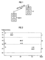
- Figure 1 shows schematically a base station NodeB, which transmits a symbol SYM to a subscriber station UE via a radio link.
- the transmitting symbol SYM is composed of three signals S1, S2, S3, each sent on a subcarrier, i. each be modulated onto a carrier frequency.
- the user station UE reconstructs the symbol SYM transmitted by the base station NodeB from the demodulated signals S1, S2, S3.
- the base station NodeB has a transmitting and receiving unit SE, which is controlled by a processor P.
- the subscriber station UE likewise has a transmitting and receiving unit SE 'and a processor P' for controlling its transmitting and receiving unit SE '.
- the base station NodeB is aware of Channel State Information (CSI) for each of the three subcarriers.
- CSI Channel State Information
- the channel state information is either measured by the subscriber station UE and signaled to the base station NodeB or determined by the base station NodeB itself.
- the base station NodeB sets a value for the transmission power of the signals S1, S2, S3.
- the abscissa shows the three signals S1, S2 and S3, while at the ordinate the receive power estimated for the three signals S1, S2, S3 for each two values of the transmit power and the values of three predetermined receive power intervals I1, 12, I3 are readable.
- the position of the signals S1, S2, S3 on the abscissa is given for example by the carrier frequency of the corresponding subcarrier.
- the first predetermined reception power interval I1 has a reception power value G1 as an upper limit and a reception power value G2 as a lower limit.
- the lower limit of the first receiving power interval I1 is simultaneously the upper limit of the second receiving power interval I2.
- the lower limit of the second reception power interval I2 has the value G3 which is simultaneously the upper limit of the third reception power interval 13.
- the lower limit of the third reception power interval 13 is G4.
- the base station NodeB estimates a first value P1 of the first subcarrier, which is determined by a first cross K1, for a first value of the transmission power which is predetermined for the first subcarrier Receiving power of the first signal S1.
- the first estimated value P1 of the received power is in the first receiving power interval I1 and is near the upper limit G1 of the first receiving power interval I1.
- the base station NodeB selects a second value of the transmission power actually used for transmitting the first signal S1, such that a second value P1 'of the received power of the first signal estimated by the second value of the transmission power, represented by a first cross in the circle K1' in the middle of the first receiving power interval I1.
- the estimated second value P1 'of the received power of the first signal S1 is thus at (G2-G1) / 2.
- the base station NodeB likewise estimates a first value P2, P3 of the received power for each of a predetermined first value of the transmission power of the signals S2, S3.
- P2 results as the first estimated value of the received power
- P3 P3 results as the first estimated value of the received power.
- the first estimated values P2, P3 of the received power of the second and third signals S2, S3 are shown in the diagram by a second and a third cross K2, K3.
- the respective predetermined first value of the transmission power has the same numerical value for all subcarriers.
- an individual predetermined first value of the transmission power can also be used for each subcarrier.
- the base station NodeB uses for transmitting the second and third signals S2, S3 each have a second value of the transmission power, so that for the respective second value of the transmission power estimated second values P2 ', P3' of the received power of the second and third signals S2, S3 respectively in of the Lie mid of the receive power intervals, in which the previously estimated for the respective predetermined first values of the transmission power values P2, P3 of the reception power were.
- the second values P2 'P3' of the received power estimated for the respective second value of the transmission power are represented by a second and third cross in the circle K2 ', K3'.
- the second estimated value P2 'of the reception power of the second signal S2 is in the middle of the second reception power interval I2, and the second estimated value P3' of the reception power of the third signal S3 is in the third reception power interval 13.
- the base station NodeB In the base station NodeB and the subscriber station UE, an assignment of the three reception power intervals I1, 12, 13 to one modulation type, for example in the form of a table, is known.
- the base station NodeB selects for transmission for the three signals S1, S2 and S3 in each case that type of modulation which is associated with the reception power interval in which the respectively first estimated values P1, P2, P3 of the received power lie.
- the base station NodeB uses the respective second value of the transmission power.
- the values of the received power of the signals S1, S2, S3 actually measured by the user station UE also have a greater probability within the corresponding reception power intervals I1, I2, I3 than would be the case when using the respectively predetermined first value of the transmission power.
- the user station UE determines the modulation method assigned to the respective reception power interval and demodulates the signals S1, S2, S3 by reversing the corresponding modulation method.
- the signals S 1, S 2, S 3 transmitted on the subcarriers may, for example, be pilot signals which the Subscriber station UE - in addition to determining modulation methods used for subcarrier signals - also serve to estimate the transmission channel of the corresponding subcarrier.
- a new receiver-side determination of the respective modulation method omitted for subsequently transmitted to the subcarrier, which serve for example for transmitting user data such as image and / or voice data, a new receiver-side determination of the respective modulation method omitted, provided that the receiver side can be assumed that the transmission conditions since the reception of the pilot signals have not changed significantly.
- the base station NodeB therefore transmits the pilot signals at a repetition rate which is the greater the faster the transmission characteristics for subcarrier signals change.
- the third reception power interval I3 there are smaller values of the reception power than in the first and second reception power intervals 12, 13. With a poor signal-to-noise ratio, it may therefore happen that the user station UE measures a value of the received power which deviates substantially from the value of the received power previously estimated by the base station NodeB. In order to prevent the actually measured value of the received power from being outside the third receiving power interval I3 in such a case and thus from the user station UE determining a modulation method other than that previously selected by the base station NodeB, the third receiving power interval I3 is wider than the second Receiving power interval 12, since the second receiving power interval I2 has greater values of the received power, as the third receiving power interval I3.
- the second reception power interval 12 is wider than the first reception power interval I1, since the first reception power interval I1 has greater values of the reception power than the second reception power interval 12.
- the width of the Receiving power intervals I1, 12, I3 can be selected, for example, such that, statistically speaking, the probability for the subscriber station UE to select a wrong modulation method on the basis of the received power interval determined by it has approximately the same value for all receiving power intervals.
- the transmission power actually used for transmitting signals of individual subcarriers is not fixed, but adapted to the transmission characteristics of the transmission channel at the frequency of the respective subcarrier such that the estimated values of the received power are each in the middle of a reception power interval ensures that the user station UE is more likely to determine the correct modulation type than would be the case if, according to known methods, all signals of the subcarriers were transmitted by the base station NodeB with the same transmission power.
- inventive method can also be used advantageously if only signals of a subcarrier are present, or if a substantially larger number of subcarriers is used than shown in Figure 2.
- the method according to the invention can also be used for transmissions from the subscriber station UE to the base station NodeB.
- the difference between the second and first values of the received power estimated for the three signals S1, S2, S3, ie P1'-P1, P2'-P2 and P3'-P3, is for example proportional to the corresponding difference of the respective second and first values of Transmission power of the base station NodeB.
- the same first predetermined value of the transmission power is obtained is used for all three signals S1, S2, S3, it can be read directly from Figure 2 that the second values of the transmission power of the first and third signals S1, S3 are smaller than the first predetermined value of the transmission power, while for the second signal S2 of second value of the transmission power is greater than the first predetermined value of the transmission power.
- the second transmission power value used for the signals S1, S2, S3 is continuously adjusted by the base station NodeB in consideration of current channel characteristics determined on the transmitter side so that further signals transmitted on the subcarriers with the adjusted transmission power likewise correspond to those for the signals S1, S2, S3 estimated second value of the received power are received by the subscriber station UE.
- a receiver-side channel estimation ie a channel estimation by the user station UE, is only required if the base station NodeB selects a value of the transmission power for signals of at least one subcarrier, for which a changed estimated value of the receiver power results in a different reception power interval.
- the base station selects, for example, a value of the transmission power, for which a changed estimated value of the received power in another receive power interval results when the channel characteristics have changed so much that, for example, it is more energetically favorable to select a new value of the transmit power and a new modulation type according to the changed receive power interval.
- the base station can keep an estimated value of the received power constant even if it is not in the middle of the reception power interval by continuously adjusting its transmission power.
Landscapes
- Engineering & Computer Science (AREA)
- Computer Networks & Wireless Communication (AREA)
- Signal Processing (AREA)
- Quality & Reliability (AREA)
- Mobile Radio Communication Systems (AREA)
- Cable Transmission Systems, Equalization Of Radio And Reduction Of Echo (AREA)
- Radar Systems Or Details Thereof (AREA)
- Transmitters (AREA)
- Radio Relay Systems (AREA)
Claims (8)
- Procédé pour déterminer une valeur de la puissance d'émission pour un signal (S1) à envoyer d'une station émettrice (NodeB) à une station réceptrice (UE), dans lequel- la position d'une première valeur (P1) probable de la puissance de réception de la station réceptrice (UE) est évaluée dans un intervalle de puissance de réception (I1) prédéfini côté émetteur pour une première valeur de la puissance d'émission- et une seconde valeur, à utiliser pour l'envoi, de la puissance de l'émission est déterminée côté émetteur de telle sorte que, lors de son utilisation, une seconde valeur (P1') probable de la puissance de réception se situe plus près du milieu de l'intervalle de puissance de réception (I1) prédéfini que la première valeur (P1) probable de la puissance de réception.
- Procédé selon la revendication 1,
caractérisé en ce qu'un type de modulation utilisé pour l'envoi du signal (S1) est choisi côté émetteur en fonction de l'intervalle de puissance de réception d'au moins deux intervalles de puissance de réception prédéfinis (I1, 12, 13) dans lequel se situe la première valeur (P1) probable, évaluée côté émetteur pour la première valeur de la première puissance d'émission, de la puissance de réception. - Procédé selon l'une quelconque des revendications précédentes,
caractérisé en ce que
la seconde valeur à utiliser pour l'émission de la puissance d'émission est déterminée côté émetteur de telle sorte que, lors de son utilisation, la seconde valeur (P1') probable de la puissance de réception se situe essentiellement au centre de l'intervalle de puissance de réception (I1) prédéfini. - Procédé selon l'une quelconque des revendications précédentes,
caractérisé en ce que
les étapes du procédé sont réalisées de façon appropriée pour d'autres signaux (S2, S3) qui sont envoyés en même temps que le signal (S1) de la station émettrice (NodeB) à la station réceptrice (UE), un signal (SYM) à transmettre par la station émettrice (NodeB) étant composé de tous ces signaux (S1, S2, S3) et les signaux (S1, S2, S3) étant envoyés au moyen de différentes fréquences porteuses. - Procédé selon l'une quelconque des revendications précédentes,
caractérisé en ce que des signaux pilotes sont utilisés comme signal (S1) et comme autres signaux (S2, S3). - Procédé selon l'une quelconque des revendications précédentes,
caractérisé en ce que
un premier intervalle de puissance de réception (I1, 12) prédéfini est plus large qu'un second intervalle de puissance de réception (12, 13) prédéfini, et en ce que les puissances de réception du premier intervalle de puissance de réception (I1, 12) prédéfini sont inférieures aux puissances de réception du second intervalle de puissance de réception (I2, 13) prédéfini. - Procédé selon l'une quelconque des revendications précédentes,
caractérisé en ce que
une valeur prédéfinie est utilisée comme première valeur de la puissance d'émission. - Dispositif (P) pour déterminer une valeur de la puissance d'émission pour un signal (S1, S2, S3) à envoyer d'une station émettrice (NodeB) à une station réceptrice (UE),- avec des moyens (P) pour l'estimation de la position d'une première valeur (P1, P2, P3) probable de la puissance d'émission de la station réceptrice (UE) dans un intervalle de puissance de réception (I1, I2, I3) prédéfini pour une première valeur de la puissance d'émission,- avec des moyens (P) pour la détermination, d'une seconde valeur, à utiliser pour l'envoi, de la puissance d'émission de telle sorte que, lors de son utilisation, une seconde valeur (P1', P2', P3') probable de la puissance de réception est située plus près du centre de l'intervalle de puissance de réception (I1, I2, I3) prédéfini que la première valeur (P1, P2, P3) probable de la puissance de réception.
Priority Applications (1)
| Application Number | Priority Date | Filing Date | Title |
|---|---|---|---|
| EP05731640A EP1762016B1 (fr) | 2004-06-28 | 2005-04-20 | Procede et dispositif de determination d'une valeur de la puissance d'emission d'un signal a emettre entre une station emettrice et une station receptrice |
Applications Claiming Priority (3)
| Application Number | Priority Date | Filing Date | Title |
|---|---|---|---|
| EP04015137A EP1612964A1 (fr) | 2004-06-28 | 2004-06-28 | Apparéil et procédé pour calculer la puissance de transmission d'un signal d'une station emettrice à une station receptrice |
| PCT/EP2005/051752 WO2006000485A1 (fr) | 2004-06-28 | 2005-04-20 | Procede et dispositif de determination d'une valeur de la puissance d'emission d'un signal a emettre entre une station emettrice et une station receptrice |
| EP05731640A EP1762016B1 (fr) | 2004-06-28 | 2005-04-20 | Procede et dispositif de determination d'une valeur de la puissance d'emission d'un signal a emettre entre une station emettrice et une station receptrice |
Publications (2)
| Publication Number | Publication Date |
|---|---|
| EP1762016A1 EP1762016A1 (fr) | 2007-03-14 |
| EP1762016B1 true EP1762016B1 (fr) | 2008-01-23 |
Family
ID=34925514
Family Applications (2)
| Application Number | Title | Priority Date | Filing Date |
|---|---|---|---|
| EP04015137A Withdrawn EP1612964A1 (fr) | 2004-06-28 | 2004-06-28 | Apparéil et procédé pour calculer la puissance de transmission d'un signal d'une station emettrice à une station receptrice |
| EP05731640A Expired - Lifetime EP1762016B1 (fr) | 2004-06-28 | 2005-04-20 | Procede et dispositif de determination d'une valeur de la puissance d'emission d'un signal a emettre entre une station emettrice et une station receptrice |
Family Applications Before (1)
| Application Number | Title | Priority Date | Filing Date |
|---|---|---|---|
| EP04015137A Withdrawn EP1612964A1 (fr) | 2004-06-28 | 2004-06-28 | Apparéil et procédé pour calculer la puissance de transmission d'un signal d'une station emettrice à une station receptrice |
Country Status (8)
| Country | Link |
|---|---|
| US (1) | US20070202820A1 (fr) |
| EP (2) | EP1612964A1 (fr) |
| CN (1) | CN1977470B (fr) |
| AT (1) | ATE385081T1 (fr) |
| BR (1) | BRPI0512733A (fr) |
| DE (1) | DE502005002677D1 (fr) |
| RU (1) | RU2350012C2 (fr) |
| WO (1) | WO2006000485A1 (fr) |
Families Citing this family (3)
| Publication number | Priority date | Publication date | Assignee | Title |
|---|---|---|---|---|
| EP1717965A1 (fr) * | 2005-04-27 | 2006-11-02 | Alcatel Alsthom Compagnie Generale D'electricite | Commande de puissance de transmission pour des liaisons HSDPA |
| US9198098B2 (en) * | 2012-11-27 | 2015-11-24 | Qualcomm Incorporated | Inter radio access technology (IRAT) measurement to improve user equipment (UE) battery performance |
| JP5726934B2 (ja) * | 2013-03-14 | 2015-06-03 | 株式会社東芝 | 制御装置、代表基地局、無線通信システム及び基地局制御方法 |
Family Cites Families (17)
| Publication number | Priority date | Publication date | Assignee | Title |
|---|---|---|---|---|
| US5893035A (en) * | 1996-09-16 | 1999-04-06 | Qualcomm Incorporated | Centralized forward link power control |
| JP3001040B2 (ja) * | 1996-09-20 | 2000-01-17 | 日本電気株式会社 | Cdmaセルラーシステム用閉ループ送信機電力制御ユニット |
| KR100306286B1 (ko) * | 1998-08-04 | 2001-09-29 | 윤종용 | 부호분할 다중접속 통신시스템의 채널 통신 장치 및 방법 |
| US6208873B1 (en) * | 1998-11-23 | 2001-03-27 | Qualcomm Incorporated | Method and apparatus for transmitting reverse link power control signals based on the probability that the power control command is in error |
| US6295289B1 (en) * | 1998-11-30 | 2001-09-25 | Nokia Mobile Phones, Ltd. | Power control in a transmitter |
| US6542558B1 (en) * | 1999-05-28 | 2003-04-01 | Telefonaktiebolaget Lm Ericsson (Publ) | Optimum turbo decoding architecture and method using a constant or quasi-constant signal-to-noise ratio |
| EP1578028B1 (fr) * | 1999-07-13 | 2009-03-25 | Alcatel Lucent | Méthode pour ameliore les performances d' un système mobile de radiocommunication en utilisant un algorithme de commande de puissance |
| US6621804B1 (en) * | 1999-10-07 | 2003-09-16 | Qualcomm Incorporated | Method and apparatus for predicting favored supplemental channel transmission slots using transmission power measurements of a fundamental channel |
| US6487420B1 (en) * | 1999-10-15 | 2002-11-26 | Telefonaktiebolaget Lm Ericsson (Publ) | Adaptive rach power determination for mobile telecommunications user equipment unit |
| US6411817B1 (en) * | 2000-01-21 | 2002-06-25 | Lucent Technologies Inc. | Method and system for dynamic downlink power control in a time-division, multiplex wireless system |
| CN100456660C (zh) * | 2000-11-17 | 2009-01-28 | Lg电子株式会社 | 在自动重发请求系统中使用确认的盲型链路适配方法 |
| US7106709B2 (en) * | 2000-11-29 | 2006-09-12 | Telefonaktiebologet Lm Ericsson (Publ) | Timing drift compensation in wireless packet-based systems |
| KR100493091B1 (ko) * | 2002-01-21 | 2005-06-02 | 삼성전자주식회사 | 고속 패킷 데이터 전송시스템에서의 전력 분배장치 및 방법 |
| US7412212B2 (en) * | 2002-10-07 | 2008-08-12 | Nokia Corporation | Communication system |
| KR100517237B1 (ko) * | 2002-12-09 | 2005-09-27 | 한국전자통신연구원 | 직교 주파수 분할 다중화 무선 통신 시스템에서의채널품질 추정과 링크적응 방법 및 그 장치 |
| US7924935B2 (en) * | 2004-09-30 | 2011-04-12 | Nortel Networks Limited | Channel sounding in OFDMA system |
| US20080002733A1 (en) * | 2006-06-30 | 2008-01-03 | Ilan Sutskover | Method and apparatus for scheduling transmissions in multiple access wireless networks |
-
2004
- 2004-06-28 EP EP04015137A patent/EP1612964A1/fr not_active Withdrawn
-
2005
- 2005-04-20 DE DE502005002677T patent/DE502005002677D1/de not_active Expired - Lifetime
- 2005-04-20 AT AT05731640T patent/ATE385081T1/de not_active IP Right Cessation
- 2005-04-20 EP EP05731640A patent/EP1762016B1/fr not_active Expired - Lifetime
- 2005-04-20 CN CN2005800218072A patent/CN1977470B/zh not_active Expired - Fee Related
- 2005-04-20 RU RU2007103183/09A patent/RU2350012C2/ru not_active IP Right Cessation
- 2005-04-20 BR BRPI0512733-5A patent/BRPI0512733A/pt not_active IP Right Cessation
- 2005-04-20 US US11/630,885 patent/US20070202820A1/en not_active Abandoned
- 2005-04-20 WO PCT/EP2005/051752 patent/WO2006000485A1/fr not_active Ceased
Also Published As
| Publication number | Publication date |
|---|---|
| CN1977470B (zh) | 2012-07-11 |
| DE502005002677D1 (de) | 2008-03-13 |
| EP1612964A1 (fr) | 2006-01-04 |
| RU2007103183A (ru) | 2008-08-10 |
| US20070202820A1 (en) | 2007-08-30 |
| RU2350012C2 (ru) | 2009-03-20 |
| WO2006000485A1 (fr) | 2006-01-05 |
| ATE385081T1 (de) | 2008-02-15 |
| CN1977470A (zh) | 2007-06-06 |
| BRPI0512733A (pt) | 2008-04-08 |
| EP1762016A1 (fr) | 2007-03-14 |
Similar Documents
| Publication | Publication Date | Title |
|---|---|---|
| DE60300227T2 (de) | Leistungsregelung in der Aufwärtsverbindung während sanften weiterreichens in einem HSDPA-System | |
| DE602004007454T2 (de) | Mobilkommunikationsgerät und Verfahren zur Sendeleistungsregelung für ein Multiplex-Funkkommunikationssystem | |
| DE69935131T2 (de) | Senderleistungssteuerung für Netzwerkgeräte in einem drahtlosen Netzwerk | |
| DE69903110T2 (de) | Funkübertragungsgerät und verfahren zur kontrolle der übertragungsrate | |
| DE60126041T2 (de) | Vorrichtung und Verfahren zur Sendeleistungsregelung in der Abwärtsrichtung (DSCH) in einem W-CDMA drahtlosen Übertragungssystem | |
| DE102005041273B4 (de) | Verfahren zum rechnergestützten Bilden von Systeminformations-Medium-Zugriffs-Steuerungs-Protokollnachrichten, Medium-Zugriffs-Steuerungs-Einheit und Computerprogrammelement | |
| DE69929504T2 (de) | Verfahren und Gerät zur Herstellung kurzer Zugriffsrahmen für schnelle Latenz | |
| DE69935396T2 (de) | Verfahren und Vorrichtung zur Leistungsregelung über Mehrschwellendetektion | |
| DE60212961T2 (de) | Prozeduren zur physischen kanalkonfigurationszeichengabe | |
| DE202005012727U1 (de) | Mobilfunkkanalmessung zur Verbesserung der Systemleistung | |
| EP1593222A1 (fr) | Procede de transmission de donnees | |
| DE202007001556U1 (de) | Dienstqualitätsbasierte Ressourcenbestimmungs- und Zuweisungsvorrichtung in Hochgeschwindigkeitspaketzugriffsevolutions- und langfristigen Evolutionssystemen | |
| DE112013003165T5 (de) | Verfahren und Systeme für adaptives Kanalbewertungs/-Vorhersage-Filterdesign | |
| EP2041938B1 (fr) | Réglage de filtre dépendant de l'occupation de la bande adjacente | |
| DE602004002883T2 (de) | Verfahren zur Verbesserung der Kapazität eines Rückverbindungskanals in einem drahtlosen Netzwerk | |
| EP1380124B1 (fr) | Procede et dispositif pour transmettre les donnees d'un canal de commande specifique a un abonne dans un systeme radio | |
| DE60225906T2 (de) | Verfahren zur Leistungssteuerung des TFCI-Datenfeldes | |
| EP1762016B1 (fr) | Procede et dispositif de determination d'une valeur de la puissance d'emission d'un signal a emettre entre une station emettrice et une station receptrice | |
| DE10046655B4 (de) | Anpassungsfähige Leistungsregelung in CDMA-Breitbandfunksystemen (WCDMA) und Verfahren zu ihrem Betrieb | |
| EP1698201B1 (fr) | Procédé permettant de faire fonctionner une station de radiodiffusion et un poste d'abonné d'un système de radiocommunication, et station de radiodiffusion et poste d'abonné correspondants | |
| EP1415411B1 (fr) | Procede, dispositifs et produit-programme informatique pour adapter la signalisation dans la liaison montante lors de la multi-diffusion | |
| WO2008043757A1 (fr) | Système de communication ofdm avec sauts de fréquence rapides | |
| DE19959179A1 (de) | Verfahren zur dynamischen Änderung von Ratenanpassungsfaktoren in einem Funk-Kommunikationssystem | |
| DE10315058A1 (de) | Datenübertragungsverfahren | |
| EP1741249B1 (fr) | Procédé, station d'abonné et dispositif de réseau pour la communication radio, en particulier dans le contexte de services HSDPA |
Legal Events
| Date | Code | Title | Description |
|---|---|---|---|
| PUAI | Public reference made under article 153(3) epc to a published international application that has entered the european phase |
Free format text: ORIGINAL CODE: 0009012 |
|
| 17P | Request for examination filed |
Effective date: 20061103 |
|
| AK | Designated contracting states |
Kind code of ref document: A1 Designated state(s): AT BE BG CH CY CZ DE DK EE ES FI FR GB GR HU IE IS IT LI LT LU MC NL PL PT RO SE SI SK TR |
|
| GRAP | Despatch of communication of intention to grant a patent |
Free format text: ORIGINAL CODE: EPIDOSNIGR1 |
|
| DAX | Request for extension of the european patent (deleted) | ||
| GRAS | Grant fee paid |
Free format text: ORIGINAL CODE: EPIDOSNIGR3 |
|
| GRAA | (expected) grant |
Free format text: ORIGINAL CODE: 0009210 |
|
| AK | Designated contracting states |
Kind code of ref document: B1 Designated state(s): AT BE BG CH CY CZ DE DK EE ES FI FR GB GR HU IE IS IT LI LT LU MC NL PL PT RO SE SI SK TR |
|
| REG | Reference to a national code |
Ref country code: GB Ref legal event code: FG4D Free format text: NOT ENGLISH |
|
| REG | Reference to a national code |
Ref country code: CH Ref legal event code: NV Representative=s name: SIEMENS SCHWEIZ AG Ref country code: CH Ref legal event code: EP |
|
| GBT | Gb: translation of ep patent filed (gb section 77(6)(a)/1977) |
Effective date: 20080128 |
|
| REG | Reference to a national code |
Ref country code: IE Ref legal event code: FG4D Free format text: LANGUAGE OF EP DOCUMENT: GERMAN |
|
| REF | Corresponds to: |
Ref document number: 502005002677 Country of ref document: DE Date of ref document: 20080313 Kind code of ref document: P |
|
| REG | Reference to a national code |
Ref country code: RO Ref legal event code: EPE |
|
| NLV1 | Nl: lapsed or annulled due to failure to fulfill the requirements of art. 29p and 29m of the patents act | ||
| PG25 | Lapsed in a contracting state [announced via postgrant information from national office to epo] |
Ref country code: ES Free format text: LAPSE BECAUSE OF FAILURE TO SUBMIT A TRANSLATION OF THE DESCRIPTION OR TO PAY THE FEE WITHIN THE PRESCRIBED TIME-LIMIT Effective date: 20080504 Ref country code: FI Free format text: LAPSE BECAUSE OF FAILURE TO SUBMIT A TRANSLATION OF THE DESCRIPTION OR TO PAY THE FEE WITHIN THE PRESCRIBED TIME-LIMIT Effective date: 20080123 Ref country code: IS Free format text: LAPSE BECAUSE OF FAILURE TO SUBMIT A TRANSLATION OF THE DESCRIPTION OR TO PAY THE FEE WITHIN THE PRESCRIBED TIME-LIMIT Effective date: 20080523 |
|
| PG25 | Lapsed in a contracting state [announced via postgrant information from national office to epo] |
Ref country code: BG Free format text: LAPSE BECAUSE OF FAILURE TO SUBMIT A TRANSLATION OF THE DESCRIPTION OR TO PAY THE FEE WITHIN THE PRESCRIBED TIME-LIMIT Effective date: 20080423 |
|
| PG25 | Lapsed in a contracting state [announced via postgrant information from national office to epo] |
Ref country code: SI Free format text: LAPSE BECAUSE OF FAILURE TO SUBMIT A TRANSLATION OF THE DESCRIPTION OR TO PAY THE FEE WITHIN THE PRESCRIBED TIME-LIMIT Effective date: 20080123 Ref country code: PT Free format text: LAPSE BECAUSE OF FAILURE TO SUBMIT A TRANSLATION OF THE DESCRIPTION OR TO PAY THE FEE WITHIN THE PRESCRIBED TIME-LIMIT Effective date: 20080623 Ref country code: PL Free format text: LAPSE BECAUSE OF FAILURE TO SUBMIT A TRANSLATION OF THE DESCRIPTION OR TO PAY THE FEE WITHIN THE PRESCRIBED TIME-LIMIT Effective date: 20080123 |
|
| BERE | Be: lapsed |
Owner name: IEMENS A.G. Effective date: 20080430 |
|
| PG25 | Lapsed in a contracting state [announced via postgrant information from national office to epo] |
Ref country code: CZ Free format text: LAPSE BECAUSE OF FAILURE TO SUBMIT A TRANSLATION OF THE DESCRIPTION OR TO PAY THE FEE WITHIN THE PRESCRIBED TIME-LIMIT Effective date: 20080123 Ref country code: DK Free format text: LAPSE BECAUSE OF FAILURE TO SUBMIT A TRANSLATION OF THE DESCRIPTION OR TO PAY THE FEE WITHIN THE PRESCRIBED TIME-LIMIT Effective date: 20080123 Ref country code: NL Free format text: LAPSE BECAUSE OF FAILURE TO SUBMIT A TRANSLATION OF THE DESCRIPTION OR TO PAY THE FEE WITHIN THE PRESCRIBED TIME-LIMIT Effective date: 20080123 Ref country code: SK Free format text: LAPSE BECAUSE OF FAILURE TO SUBMIT A TRANSLATION OF THE DESCRIPTION OR TO PAY THE FEE WITHIN THE PRESCRIBED TIME-LIMIT Effective date: 20080123 Ref country code: SE Free format text: LAPSE BECAUSE OF FAILURE TO SUBMIT A TRANSLATION OF THE DESCRIPTION OR TO PAY THE FEE WITHIN THE PRESCRIBED TIME-LIMIT Effective date: 20080423 |
|
| EN | Fr: translation not filed | ||
| PG25 | Lapsed in a contracting state [announced via postgrant information from national office to epo] |
Ref country code: MC Free format text: LAPSE BECAUSE OF NON-PAYMENT OF DUE FEES Effective date: 20080430 |
|
| PLBE | No opposition filed within time limit |
Free format text: ORIGINAL CODE: 0009261 |
|
| STAA | Information on the status of an ep patent application or granted ep patent |
Free format text: STATUS: NO OPPOSITION FILED WITHIN TIME LIMIT |
|
| 26N | No opposition filed |
Effective date: 20081024 |
|
| PG25 | Lapsed in a contracting state [announced via postgrant information from national office to epo] |
Ref country code: LT Free format text: LAPSE BECAUSE OF FAILURE TO SUBMIT A TRANSLATION OF THE DESCRIPTION OR TO PAY THE FEE WITHIN THE PRESCRIBED TIME-LIMIT Effective date: 20080123 Ref country code: EE Free format text: LAPSE BECAUSE OF FAILURE TO SUBMIT A TRANSLATION OF THE DESCRIPTION OR TO PAY THE FEE WITHIN THE PRESCRIBED TIME-LIMIT Effective date: 20080123 |
|
| PG25 | Lapsed in a contracting state [announced via postgrant information from national office to epo] |
Ref country code: BE Free format text: LAPSE BECAUSE OF NON-PAYMENT OF DUE FEES Effective date: 20080430 |
|
| REG | Reference to a national code |
Ref country code: CH Ref legal event code: PCAR Free format text: SIEMENS SCHWEIZ AG;INTELLECTUAL PROPERTY FREILAGERSTRASSE 40;8047 ZUERICH (CH) |
|
| PG25 | Lapsed in a contracting state [announced via postgrant information from national office to epo] |
Ref country code: FR Free format text: LAPSE BECAUSE OF FAILURE TO SUBMIT A TRANSLATION OF THE DESCRIPTION OR TO PAY THE FEE WITHIN THE PRESCRIBED TIME-LIMIT Effective date: 20081114 |
|
| PG25 | Lapsed in a contracting state [announced via postgrant information from national office to epo] |
Ref country code: CY Free format text: LAPSE BECAUSE OF FAILURE TO SUBMIT A TRANSLATION OF THE DESCRIPTION OR TO PAY THE FEE WITHIN THE PRESCRIBED TIME-LIMIT Effective date: 20080123 |
|
| PG25 | Lapsed in a contracting state [announced via postgrant information from national office to epo] |
Ref country code: IT Free format text: LAPSE BECAUSE OF FAILURE TO SUBMIT A TRANSLATION OF THE DESCRIPTION OR TO PAY THE FEE WITHIN THE PRESCRIBED TIME-LIMIT Effective date: 20080123 Ref country code: AT Free format text: LAPSE BECAUSE OF NON-PAYMENT OF DUE FEES Effective date: 20080420 |
|
| PG25 | Lapsed in a contracting state [announced via postgrant information from national office to epo] |
Ref country code: LU Free format text: LAPSE BECAUSE OF NON-PAYMENT OF DUE FEES Effective date: 20080420 Ref country code: HU Free format text: LAPSE BECAUSE OF FAILURE TO SUBMIT A TRANSLATION OF THE DESCRIPTION OR TO PAY THE FEE WITHIN THE PRESCRIBED TIME-LIMIT Effective date: 20080724 |
|
| PG25 | Lapsed in a contracting state [announced via postgrant information from national office to epo] |
Ref country code: TR Free format text: LAPSE BECAUSE OF FAILURE TO SUBMIT A TRANSLATION OF THE DESCRIPTION OR TO PAY THE FEE WITHIN THE PRESCRIBED TIME-LIMIT Effective date: 20080123 |
|
| PG25 | Lapsed in a contracting state [announced via postgrant information from national office to epo] |
Ref country code: GR Free format text: LAPSE BECAUSE OF FAILURE TO SUBMIT A TRANSLATION OF THE DESCRIPTION OR TO PAY THE FEE WITHIN THE PRESCRIBED TIME-LIMIT Effective date: 20080424 |
|
| PGFP | Annual fee paid to national office [announced via postgrant information from national office to epo] |
Ref country code: RO Payment date: 20150323 Year of fee payment: 11 |
|
| PGFP | Annual fee paid to national office [announced via postgrant information from national office to epo] |
Ref country code: GB Payment date: 20150414 Year of fee payment: 11 Ref country code: DE Payment date: 20150619 Year of fee payment: 11 |
|
| PGFP | Annual fee paid to national office [announced via postgrant information from national office to epo] |
Ref country code: IE Payment date: 20150427 Year of fee payment: 11 |
|
| PGFP | Annual fee paid to national office [announced via postgrant information from national office to epo] |
Ref country code: CH Payment date: 20150702 Year of fee payment: 11 |
|
| REG | Reference to a national code |
Ref country code: DE Ref legal event code: R119 Ref document number: 502005002677 Country of ref document: DE |
|
| REG | Reference to a national code |
Ref country code: CH Ref legal event code: PL |
|
| GBPC | Gb: european patent ceased through non-payment of renewal fee |
Effective date: 20160420 |
|
| REG | Reference to a national code |
Ref country code: IE Ref legal event code: MM4A |
|
| PG25 | Lapsed in a contracting state [announced via postgrant information from national office to epo] |
Ref country code: RO Free format text: LAPSE BECAUSE OF NON-PAYMENT OF DUE FEES Effective date: 20160420 Ref country code: CH Free format text: LAPSE BECAUSE OF NON-PAYMENT OF DUE FEES Effective date: 20160430 Ref country code: DE Free format text: LAPSE BECAUSE OF NON-PAYMENT OF DUE FEES Effective date: 20161101 Ref country code: LI Free format text: LAPSE BECAUSE OF NON-PAYMENT OF DUE FEES Effective date: 20160430 Ref country code: GB Free format text: LAPSE BECAUSE OF NON-PAYMENT OF DUE FEES Effective date: 20160420 |
|
| PG25 | Lapsed in a contracting state [announced via postgrant information from national office to epo] |
Ref country code: IE Free format text: LAPSE BECAUSE OF NON-PAYMENT OF DUE FEES Effective date: 20160420 |