EP1762049B1 - Verfahren zur schnellen bestimmung von verbindungswegen in virtuellen privaten netzwerken mit mehreren domänen - Google Patents
Verfahren zur schnellen bestimmung von verbindungswegen in virtuellen privaten netzwerken mit mehreren domänen Download PDFInfo
- Publication number
- EP1762049B1 EP1762049B1 EP05753842.3A EP05753842A EP1762049B1 EP 1762049 B1 EP1762049 B1 EP 1762049B1 EP 05753842 A EP05753842 A EP 05753842A EP 1762049 B1 EP1762049 B1 EP 1762049B1
- Authority
- EP
- European Patent Office
- Prior art keywords
- domain
- information
- vpn
- connection path
- connection
- Prior art date
- Legal status (The legal status is an assumption and is not a legal conclusion. Google has not performed a legal analysis and makes no representation as to the accuracy of the status listed.)
- Expired - Lifetime
Links
Images




Classifications
-
- H—ELECTRICITY
- H04—ELECTRIC COMMUNICATION TECHNIQUE
- H04L—TRANSMISSION OF DIGITAL INFORMATION, e.g. TELEGRAPHIC COMMUNICATION
- H04L12/00—Data switching networks
- H04L12/28—Data switching networks characterised by path configuration, e.g. LAN [Local Area Networks] or WAN [Wide Area Networks]
-
- H—ELECTRICITY
- H04—ELECTRIC COMMUNICATION TECHNIQUE
- H04L—TRANSMISSION OF DIGITAL INFORMATION, e.g. TELEGRAPHIC COMMUNICATION
- H04L63/00—Network architectures or network communication protocols for network security
- H04L63/02—Network architectures or network communication protocols for network security for separating internal from external traffic, e.g. firewalls
- H04L63/0272—Virtual private networks
-
- H—ELECTRICITY
- H04—ELECTRIC COMMUNICATION TECHNIQUE
- H04L—TRANSMISSION OF DIGITAL INFORMATION, e.g. TELEGRAPHIC COMMUNICATION
- H04L12/00—Data switching networks
- H04L12/28—Data switching networks characterised by path configuration, e.g. LAN [Local Area Networks] or WAN [Wide Area Networks]
- H04L12/46—Interconnection of networks
- H04L12/4641—Virtual LANs, VLANs, e.g. virtual private networks [VPN]
Definitions
- the present invention relates in general to virtual private networks in communications systems and in particular to determination of connection paths of virtual private networks in multi-domain communications systems.
- VPN Virtual Private Network
- a company or other customer that wanted to build a wide-area network had to provide for its own dedicated lines between each node to provide the connectivity.
- Such solutions are, however, generally expensive and inflexible.
- VPNs offer a solution, where a communications network is shared between many customers, but where the communication of each customer is virtually separated.
- VPN technology is often based on the idea of tunnelling.
- Network tunnelling involves establishing and maintaining a logical network connection. On this connection, packets are encapsulated within some other base or carrier protocol. They are then transmitted between VPN client and server and eventually de-encapsulated on the receiver side. Authentication and encryption assists in providing security.
- a tendency is that the number of network nodes that form a VPN grows fast, which results in large complex network structures and topology. This is caused, partly because of the increasing traffic on VPNs and partly on that the VPNs are requested to cover larger and larger geographical areas. Communication networks providing VPNs having nodes at all continents are present today. However, the more nodes and the more traffic that is to be transmitted, the more complex the configuration of VPNs becomes.
- a VPN is created according to an agreement between a network operator and a customer.
- the location of the nodes, the quality of service and other conditions are agreed on and a programmer at the operator sets up the configuration manually or by consulting configuration aid tools.
- configuration becomes more and more complex and time consuming.
- a customer wants to modify its VPN the entire procedure has to be repeated.
- a general problem of prior-art solutions is thus that communications networks providing virtual private networks having a large geographical coverage and/or having large traffic become very complex.
- a further problem is that configuration of new VPNs or modifications of already existing VPNs become complex and time consuming, in particular in networks having large topology dynamics.
- a further problem is that communication resources of network operators covering smaller geographical areas cannot be generally utilised for wide-area VPNs.
- a general object of the present invention is thus to improve methods for determining connection paths of VPNs as well as providing systems and devices suitable therefore.
- a further object of the present invention is to provide methods for finding connection paths of VPNs utilising more than one network domain.
- Another further object of the present invention is make methods and arrangements for determining useable connection paths in multi-domain networks faster.
- an information request about a certain VPN is sent from a first domain to an adjacent domain. If the adjacent domain has information available about how to reach the VPN in question, such connection path information is returned to the requesting domain. If the suitable connection path information is not available in the domain, the request is forwarded to further adjacent domains, whereby the information request is propagated through the communication network in a cascaded manner. When the appropriate VPN or connection path information thereof is found, this information is returned to the originally requesting domain, preferably along the same path as the request has been forwarded, but in opposite direction. The connection path is thereby achieved by a cascaded information pull mechanism.
- the method and arrangements comprises means for prohibiting endless loops of information requests among the network domains.
- the connection path information could in the simplest form be just an acknowledgement that the requested VPN is reachable through the domain in question.
- information about the links to use is comprised in the connection path information.
- forwarding of the information request is performed also when there is information about the requested VPN available in the domain. This enables findings of alternative or additional paths to the requested VPN, whereby reconfiguring or additional configuring can be performed at a later stage.
- the domain VPN information is made available for supporting VPN configuration in essentially all domains of a multi-domain system in a fast manner, which is essential in networks having a dynamic topology.
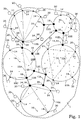
- FIG. 1 An embodiment of a general VPN provider architecture 1 is illustrated in Fig. 1 .
- this VPN Provider Architecture there are five VPN Provider Domains 10A-E present, which are attached to each other by interdomain data connections 12A-G.
- One operator may control one or more of these domains 10A-E, or they can all be controlled by separate operators.
- the relation between the domains 10A-E, i.e. the control of the interdomain data connections 12A-G are typically regulated according to agreements between the involved operators, e.g. a VPN Service Level Agreement (SLA).
- SLA VPN Service Level Agreement
- Each VPN provider domain 10A comprises VPN edge nodes 14 and core nodes 16, which can be VPN aware or VPN unaware, of which only a few are provided with reference numbers.
- the VPN edge nodes 14 are nodes through which customer sites 20 of different customers are connected to different VPN's in the architecture 1.
- VPN unaware nodes 16 are just intermediate nodes within a domain and is only used for forwarding messages and data between VPN edge nodes 14. The customers are unaware of which VPN unaware nodes that are used for the communication. The only important matter is the starting and ending VPN edge node 14.
- a VPN connected in a domain can thus be represented by a direct line between VPN edge nodes 14, even if the actual communication may take place via one or several VPN unaware nodes 16.
- the existence of VPN unaware nodes will in general be neglected, since the basic procedural steps according to the present invention are not directly dependent on the existence of any VPN unaware nodes 16 or not. In the practical implementation, it is, however, likely that VPN unaware nodes 16 are used for providing the actual connectivity.
- the VPN provider domains 10A-E are connected in a data plane via VPN border nodes 18, i.e. the interdomain data connections 12A-G start and end in a VPN border node 18.
- the VPN border node 18 may or may not at the same time also act as a VPN edge node 14.
- a customer site 20 is connected to one of the VPN edge nodes 14.
- Customer sites 20 of the same customer may then be connected through the VPN provider domains 10A-E by a VPN 22A-C.
- One customer may have customer sites 20 connected to different VPN's 22A-C.
- more than one customer site 20 can be connected to the same VPN edge node 14, but will be unaware of the existence of the other customer site 20 as well as of the VPN to which the other customer site 20 is connected.
- VPN's 22A-C are illustrated. However, anyone skilled in the art realises that the number of VPN's in a real system typically is much higher.
- a first VPN 22A illustrated by broken lines, is extended over three domains 10A, 10C, 10D and connects customer sites 20 in all of these domains.
- a second VPN 22B illustrated by dotted lines, is extended over all domains 10A-E of the present embodiment.
- a third VPN 22C illustrated by a dash-dotted line, connects customer sites 20 only within the domain 10B.
- Each customer site 20 is unaware of the existence of customer sites 20 of other customers as well as of the existence of any VPN's except the one it is connected to. In such a manner, the privacy character of the VPN's is preserved, although they all share the same basic communications resources. This is the scenario in which the present invention preferably operates.
- connections are discussed - interdomain, intradomain, user plane connections, control plane connections, overlay control connections, connections between nodes and user terminals etc. It is assumed throughout the entire description that these connections can be of any kind. The basic idea of the present invention is not dependent on the actual connection technology. This means that both wired and wireless technologies can be used for any of these connections.
- the user terminals can be mobile relative to the edge nodes. The nodes within a domain can be mobile relative to the other nodes. Even the domains may be mobile relative to each other.
- a path to the requested VPN 22A or 22C can be found.
- a network having a dynamic topology i.e. where the number of domains and/or connections between domains and/or connections within the domains are changing quite often, the efforts to keep all parties informed about the present topology may become quite extensive. For instance, information about a change may e.g. be on its way, when a connection path is decided on according to old topology information. In most practical cases, a connection path according to prevailing topology situation has to be found.
- One basic idea of the present invention is to find a first sufficient connection path to the requested VPN as fast as possible. Any reconfiguring or additional configuring can then be performed at a later occasion.
- An information request about the requested VPN has to be spread through the communication network domains, and path information should be returned as fast as possible.
- the information request is forwarded to adjacent domains, at least when no adequate information is available in the domain. Any replies are then returned basically along the same path as the request was sent.
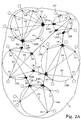
- Fig. 2A illustrates an embodiment of an initial phase of providing domain VPN information.
- Each VPN edge node 14 has stored information reflecting its own present VPN configuration regarding at least which VPN's that have connected customer sites at that particular VPN edge node 14.
- the VPN edge node 14 has information also about which customers that are connected to the VPN edge node 14 and associations between the present VPN's and customer sites 20.
- information such as VPN address space and address type (local or global), VPN quality of service classes, specified by requirements such as bandwidth, delay and jitter, and/or VPN set-up, i.e. use of tunnels or filters is provided.
- information such as encryption properties, transparency layer properties, tunnelling properties and topology properties can be included.
- the VPN border nodes 18 have stored information about the identity of the VPN provider domain it belongs to.
- the domain VPN information stored in each VPN edge node 14, or at least parts thereof is collected by each border node 18 in the same domain 10A-E.
- This is visualised in Fig. 2A as arrows, of which some are provided with reference number 24.
- the collective domain node information for the own domain is available in each VPN border node 18 of each domain 10A-E.
- One alternative for the communication is to use a communication protocol similar to BGP (Border Gateway Protocol), spreading the information all over the domain without any particular knowledge about where the need for information is.
- the border nodes may then pick up all necessary information. This is an example of a push mechanism for distributing domain VPN information.
- Fig. 2B illustrates another embodiment for providing domain VPN information, now concentrated to one domain 10C.
- the VPN border nodes 18 can simply request 23 any VPN edge node 14 to return its domain node information 24.
- the request itself could be a question if the VPN edge node 14 is associated to a certain VPN or not, e.g. received by the domain interconnection 12F.
- An acknowledgement message will in such a case not comprise any information as such, but will implicitly transfer information of this particular VPN at that particular VPN edge node. This is an example of a pull mechanism for distributing domain VPN information.
- the domain VPN information can also be collected with different timing.
- One alternative is to continuously or at least regularly collect such information to the border nodes in order to assure that the available information always is updated.
- the information is preferably stored in the border nodes or in any other node where it is retrievable from the border node, see embodiments described further below.
- Another alternative is that the information collection is triggered by some event. This event could e.g. be a broadcasting message from an edge node that there is a change of some kind or, as being described above, a request for finding a particular VPN. If all edge nodes have knowledge about which border nodes that are available in the domain, the information could also be sent directly to all border nodes when such a change occurs. In case the information is searched as triggered by a request to find a certain VPN, the collected information may be restricted to that VPN and may not even necessarily be stored for later use.
- Fig. 2C illustrates an embodiment, where the domain VPN information is collected in a centralised manner.
- a storage 54 is provided to store all domain VPN information 24 provided by the different edge nodes 14. Any functionalities using such domain VPN information can the retrieve this information from the central storage 54.
- Fig. 2D illustrates another embodiment based on a centralised collection of domain VPN data.
- a request 23 or other external signal can initialise the provision of VPN data 24 to the storage 54.
- This request 23 does not necessarily have to come from the storage itself 54.
- the domain VPN information may instead be provided by retrieving data from a data storage.
- This stored data could e.g. be the result of a previous collection of data according to the procedures above, or could be provided from elsewhere.
- the border nodes 18 are responsible for the data traffic to and from other domains by the data connections 12A and 12B.
- the border nodes 18 comprise in this particular embodiment means 41 for collecting domain VPN information, in the form of e.g. software functionality in the processors of the border node 18.
- the domain VPN information can be stored in a storage 54.
- a VPN control node 43 for handling domain VPN information regarding the domain as a whole is thus in this particular embodiment implemented as a distribution of local means 41 at every border node 18.
- a distributed VPN control node 43 comprises in this particular embodiment means 41 for providing domain VPN information situated in or in connection with the border nodes 18 and a central database 54.
- the central database 54 the actual updated and preferably also historical VPN information is stored.
- the VPN control node 43 is centralised and comprises the means 41 for providing domain VPN information and the central database 54 basically provided at the same location.
- the border nodes 18 are in this particular embodiment merely used for handling communications 45 between the VPN control node and neighbouring domains. Functionalities in the border nodes 18 regarding control signalling associated with the actual data traffic can in such a way be utilised also to signal control messages concerning VPN configuration.
- Fig. 3D an embodiment having a VPN control node 43 that is virtually separated from the border nodes in the system is illustrated.
- the VPN control node 43 is in such an embodiment connected to VPN control nodes in other domains by dedicated VPN control signal connections 47, creating a high-level network of its own.
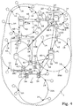
- FIG. 4 A particular embodiment of the present invention is illustrated in Fig. 4 .
- the first step is provision of VPN information within each domain. This is performed by a VPN control node 43 in each domain.
- the configuration of the VPN control nodes 43 may differ between the different domains.
- domain 10A has a VPN control node 43 similar to the example shown in Fig. 3A
- domain 10C has a VPN control node 43 similar to the example shown in Fig. 3B
- domains 10B, 10D and 10E have VPN control nodes 43 similar to the example shown in Fig. 3C .
- the VPN control nodes 43 now only have information about its own domain VPN's.
- the VPN control node 43 When the VPN control node 43 initiates a connect request of the VPN control node 43 of its own domain 10E, it does only have the information about VPNs in the own domain readily available in its own databases. However, the VPN control node 43 knows what domains it is connected to and sends instead an information request over the interdomain connection 12A-G to the neighbouring, adjacent domains, concerning information about any existence of the requested VPN. This is illustrated by the arrows 32. A VPN control node 43 receiving such information request over an interdomain connection investigates its own databases of domain VPN information to see if there are any data of interest. If the comparison finds any connection path information for the requested VPN, such connection path information is returned to the domain sending the request.
- connection path information follows preferably the same path as the information request was delivered, but in the opposite direction.
- the returning of connection path information can be performed in a similar manner as the request, i.e. the connection path information is returned to adjacent domains. If these domains are not the domain issuing the request, the connection path information is forwarded to further adjacent domains in a cascaded manner until it reaches the original domain.
- This particular embodiment has the advantage that not the entire system 1 has to be updated in every single VPN control node 43.
- the VPN SLA (c.f. description about Fig. 1 ) may comprise agreements about how much of the available information that should be made available for the neighbouring domain.
- the VPN control node processes available intradomain VPN information into compiled or processed VPN information that is suitable to return as connection path information to neighbouring domains. If the domains are closely related, e.g. belonging to the same operator, the SLA could involve a total transparency in exchanging domain VPN information.
- the processed information 28 that is transferred between the VPN control nodes 43 may be compiled VPN information, only revealing very basic fact about the individual domain VPNs.
- the minimum information that has to be sent over the interdomain connections 12A-G in the present embodiment is if the requested VPN is available somewhere beyond the border node or domain that returns the information.
- the information 28 returned on the interdomain connections 12A-G causes an update or extension of the total available VPN information situation at the VPN control node receiving this reply.
- the VPN information is thereby extended by connection path information returned by the further adjacent domain.
- This VPN control node now also has information e.g. of what VPN's that are available via the interdomain connections. If more thorough information is available, the VPN control node may also determine e.g. edge node identities at which these different VPN's are available, VPN quality of service etc.
- the so achieved VPN information is now a property of the neighbour or adjacent domain and can, if allowed by the SLA, be used for activities in that domain.
- the information stored in the storage 54 of the VPN control node 43 could be identical to the information received from the neighbouring domain or a processed version thereof, adding, removing or modifying the received information. For instance, the information could be labelled with an indication from what domain it originated from.
- a communications network 1 comprises five domains 10A-E.
- domain 10E a VPN 22A is available.
- Domain 10A has no internal information about that VPN and creates and sends an information request to both its adjacent domains 10B and 10E.
- a reply is achieved, giving necessary information for initiating a configuring of a connection to the VPN 22A.
- domain 10B no information about VPN 22A is available.
- the information request is therefore forwarded to the further adjacent domains 10C and 10D. None of these domains have any information about VPN 22A, and another forwarding of the information request is performed.
- Domain 10C sends the request to the domain 10D and the domain 10D sends the request to the domain 10C.
- the procedure continues, and an endless loop of information requests will circulate between domains 10B-D.
- means for prohibiting the information requests to be forwarded in endless loops are provided.
- Such means for prohibiting looping of information requests are preferably provided in connection with sending or receiving of such information requests, i.e. they are arranged either to prohibit the actual forwarding to a new adjacent domain or to prohibit the acceptance of a received information request.
- each original information request is provided with an identity.
- This identity could e.g. be a separate field having a certain unique identity number.
- Identities of information requests received and accepted by a domain are stored in a storage. When a new information request arrives, a comparison is made with the stored data to reveal if the information request already has been received before. In such a case, the request is neglected. Otherwise the request is accepted and the identity is added to the storage.
- the identity of the request could also be composed by the identity of the originally requesting domain and the identity of the requested VPN. In such a case, no separate request identity is necessary. However, in such a case, the storage of received information requests should be associated with a certain life-time, so that new requests for the same domain-VPN pair can be allowed after a certain time.
- the comparison could also be performed in connection with the actual forwarding of the request.
- the request identity could be stored in the storage and an extra condition for forwarding the request could be that there should not be two identical request identities within the database.
- Another embodiment for loop prohibiting is based on information about forwarding paths.
- a receiving domain can easily search for its own identity among this information. If the own identity is present, the request is neglected. Otherwise, the own identity is added and the request can be forwarded.
- the comparison can also be made at the sending side. Before forwarding a request to a domain, the sending domain searches the forwarding path information for the identities of its adjacent domains. For domains which already are present in the forwarding path, forwarding is prohibited.
- Yet another embodiment is based on life-time.
- a certain life-time can be set when creating the original information request, e.g. by fixing a validity expiration time. When receiving and/or forwarding a request, this validity expiration time is checked against e.g. a system time, and when the validity is expired, no more forwarding is performed.
- a variation of the lime-time concept is to set a remaining life-time, which then is reduced in connection to each forwarding. When the remaining life-time vanishes, no more forwardings are performed.
- This approach can then also be used, utilising the number of forwardings as a measure of "time", i.e. it is stated from the initialisation that a maximum number of forwardings is allowed. For each forwarding, the remaining number is reduced by one unit.
- the process of finding a connection path to a certain VPN is typically used for configuring a new connection to the VPN.
- the returned information is typically used for during this configuration. If the returned connection path information comprises full information about the path, the configuration can be performed straightforward. If the connection path information just reveals the mere existence of a VPN beyond a certain adjacent domain, also the configuration has to be performed in one domain at a time.
- FIG. 7 An example, illustrated in Fig. 7 , shows how the configuration of an interdomain VPN can be performed.
- a new customer site 20' in the domain 10E shall be connected to VPN 22A. It is assumed that VPN tunnels are used for VPN connections both inside domains and between domains. The following steps are taken.
- the VPN control node in domain 10E gets connection path information that a connection can be set up to the VPN via the "nexthop" 10B. No further information is available.
- the VPN control node in domain 10E sets up a VPN tunnel 71 for VPN 22A from the edge node 14' where the customer site 20' is connected, to the border node 18:1, which is connected to domain 10B via link 12D.
- the VPN control node in domain 10E initiates communication with the VPN control node in domain 10B and sets up a VPN tunnel 72 for VPN 22A over the link 12D to border node 18:2. Since VPN 22A is not present in domain 10B, the VPN control node in domain 10B checks its VPN database and sees that VPN 22A can be found at "nexthop" 10A and 10C.
- the VPN control node in domain 10B chooses to set up the VPN via the "nexthop" 10A only. It sets up a VPN transit tunnel 73 for VPN 22A from the border node 18:2, which is connected to domain 10B via link 12D, to the border node 18:3, which is connected to domain 10A via link 12A.
- the VPN control node in domain 10B initiates communication with the control node in domain 10A and sets up a VPN tunnel 74 over the link 12A to border node 18:4. Since VPN 22A is present in domain 10A, the control node in domain 10A can set up an internal tunnel 75 from the border node, which is connected to domain 10B via link 12A, to the border node 18:5, which is connected to the VPN 22A.
- the present invention provides a fast determination of a possible connection path to a VPN.
- this path may not be the optimum one, at least not for all possible situations. In such cases, a later revision of the connection path could be beneficial. If there are alternative paths available, it is likely that subsequent replies defining such alternative paths are provided to the original domain. Furthermore, by letting the information request be forwarded, not only from domains lacking information about the requested VPN, but from all domains, virtually all possible paths will be found and returned to the originating domain.
- the originating domain can thereby evaluate this further information about alternative paths, preferably in terms of any connection quality, and can perform any actions based on this. If a better connection path is found, one alternative is to reconfigure the VPN and switch over to the new path instead, leaving the first temporary connection path. Another alternative would be to configure an additional connection.
- the functionalities according to the present invention are provided in the different domains.
- Functionalities for receiving, comparing, returning replies and forwarding are preferably available in all domains that may be subject of a request.
- Functionalities for creating and sending the original request as well as for performing actual configurations are preferably available in all domains where new nodes could appear.
- the domain arrangements are typically implemented in VPN control nodes 43 of the domains.
- Fig. 6 illustrates a block scheme of a particular embodiment of a relatively general VPN control node 43 according to the present invention providing the connection path finding assistance arrangement.
- the VPN control node 43 comprises means 52 for providing domain VPN information. This information may be provided by other nodes in the domain by connections 62.
- a main control communication interface 40 is provided for communication with other domains. This interface 40 may be arranged in combination with the intra-domain connections 62.
- a receiver 41 is connected to the main control communication interface 40 and is arranged to handle any incoming information requests. The receiver 41 is further arranged to receive any connection path information sent from any further adjacent domain.
- a matching unit 49 investigating if an identity of a requested VPN matches with domain VPN information is provided, as means for comparing.
- a transmitter 42 is also connected to the main control communication interface 40 for returning information about any matched connection path information from the matching unit 49 to adjacent domains. This unit is also responsible to forward any reply received from any further adjacent domain backwards in the request chain.
- a forwarding unit 44 is also provided, which forwards any non-matching request to further adjacent domains. In the present embodiment, also loop-prohibiting functionalities are comprised in this forwarding unit 44.
- the transmitter 42 and the forwarding unit 44 are preferably implemented in together in one common unit.
- an information request unit 45 is provided for the VPN control node 43 also to function as a request initiating node.
- the forwarding unit 44 is then utilised for sending the information request to an adjacent domain.
- a configuring machine 46 is provided and arranged to use the received connection path information for initialising a configuration of the VPN connection. This configuring machine 46 preferably comprises means for performing evaluations and configurations of alternative connection paths according to the discussions further above.
- step 200 an information request about any existence of a certain VPN is created. This request concerns connecting a first node in a first domain to a VPN not presently available in the first domain.
- step 212 the information request is sent to an adjacent domain.
- step 214 the information request is compared with domain VPN information available in the adjacent domain.
- step 216 it is decided whether or not suitable connection path information is available or not. If suitable connection path information is available, the process continues to step 218, where connection path information is returned to the domain sending the information request. The procedure ends in step 299. If suitable connection path information is not available, the process continues to step 220, where the information request is forwarded to further adjacent domains. If the forwarding step succedes the procedure returns to step 214, as illustrated by the arrow 250, otherwise the procedure ends in step 299.
Landscapes
- Engineering & Computer Science (AREA)
- Computer Networks & Wireless Communication (AREA)
- Signal Processing (AREA)
- Computer Security & Cryptography (AREA)
- Computer Hardware Design (AREA)
- Computing Systems (AREA)
- General Engineering & Computer Science (AREA)
- Data Exchanges In Wide-Area Networks (AREA)
- Telephonic Communication Services (AREA)
- Small-Scale Networks (AREA)
- Communication Control (AREA)
- Mobile Radio Communication Systems (AREA)
Claims (25)
- Verfahren zum Bestimmen eines Verbindungswegs zu einem virtuellen privaten Netzwerk (22 A-C) - VPN - innerhalb eines Kommunikationsnetzwerks mit mindestens zwei miteinander verbundenen Domains (10 A-E), und zwar von einem ersten Knoten in einer ersten Domain zu einem zweiten Knoten, der einem Ziel-VPN zugeordnet ist, das ursprünglich in der ersten Domain nicht verfügbar ist, wobei das Verfahren die Schritte umfasst:von einem VPN-Steuerungsknoten der ersten Domain an einen VPN-Steuerungsknoten einer benachbarten Domain erfolgendes Senden (212) einer Informationsanfrage über eine Existenz des Ziel-VPN in der benachbarten Domain, worin die Informationsanfrage eine Identität des Ziel-VPN umfasst;durch den VPN-Steuerungsknoten der benachbarten Domain erfolgendes Vergleichen (214) der empfangenen Informationsanfrage mit der VPN-Information der benachbarten Domain, die im VPN-Steuerungsknoten der benachbarten Domain verfügbar ist;durch den VPN-Steuerungsknoten der benachbarten Domain zum VPN-Steuerungsknoten der ersten Domain erfolgendes Zurücksenden (218) von Verbindungsweginformation von der benachbarten Domain zur ersten Domain, wenn in der Domain-VPN-Information, die in der benachbarten Domain verfügbar ist, Information über einen Verbindungsweg zum Ziel-VPN vorliegt; unddurch den VPN-Steuerungsknoten der benachbarten Domain zu einem VPN-Steuerungsknoten einer weiteren benachbarten Domain erfolgendes Weiterleiten (220) der Informationsanfrage über die Existenz des Ziel-VPN in der weiteren benachbarten Domain, wenn in der Domain-VPN-Information, die im VPN-Steuerungsknoten der benachbarten Domain verfügbar ist, keine Information über einen Verbindungsweg zum Ziel-VPN vorliegt.
- Verfahren zum Bestimmen eines Verbindungswegs nach Anspruch 1, worin die Vergleichs-, Zurücksende- und Weiterleitungsschritte in weiteren benachbarten Domains auf kaskadierte Weise wiederholt werden, wobei der Weiterleitungsschritt in den weiteren benachbarten Domains weiteren Bedingungen unterliegt.
- Verfahren zum Bestimmen eines Verbindungswegs nach Anspruch 2, worin die Verbindungsweginformation entlang des gleichen Wegs zur ersten Domain zurückgesendet wird, wie die Informationsanfrage weitergeleitet wurde, aber in entgegengesetzter Richtung.
- Verfahren zum Bestimmen eines Verbindungswegs nach Anspruch 3, worin die in einer vorliegenden Domain verfügbare Domain-VPN-Information mit Verbindungsweginformation erweitert wird, die durch eine weitere benachbarte Domain zurückgesendet wurde, wodurch erweiterte Verbindungsweginformation aus der vorliegenden Domain wiederum zu einer Domain zurückgesendet wird, welche die Informationsanfrage an die vorliegende Domain liefert.
- Verfahren zum Bestimmen eines Verbindungswegs nach Anspruch 2, worin die Verbindungsweginformation durch Kaskadieren der Verbindungsweginformation zu benachbarten Domains zur ersten Domain zurückgesendet wird.
- Verfahren zum Bestimmen eines Verbindungswegs nach einem der Ansprüche 1 bis 5, worin der Schritt des Weiterleitens auch durchgeführt werden kann, wenn in der Domain-VPN-Information, die in der benachbarten Domain verfügbar ist, Information über einen Verbindungsweg zum Ziel-VPN vorliegt.
- Verfahren zum Bestimmen eines Verbindungswegs nach einem der Ansprüche 1 bis 6, worin die Verbindungsweginformation Information umfasst, die eine Existenz eines möglichen Wegs zwischen dem ersten Knoten und dem Ziel-VPN bestätigt.
- Verfahren zum Bestimmen eines Verbindungswegs nach einem der Ansprüche 1 bis 6, worin die Verbindungsweginformation Information über alle Verbindungsstrecken eines möglichen Wegs zwischen dem ersten Knoten und dem Ziel-VPN umfasst.
- Verfahren zum Bestimmen eines Verbindungswegs nach einem der Ansprüche 1 bis 8, den weiteren Schritt umfassend: Unterbinden, dass die Informationsanfragen innerhalb des Kommunikationsnetzwerks in Endlosschleifen weitergeleitet werden.
- Verfahren zum Bestimmen eines Verbindungswegs nach Anspruch 9, worin der Schritt des Unterbindens vor dem Weiterleiten einer Informationsanfrage zu einer weiteren benachbarten Domain durchgeführt wird.
- Verfahren zum Bestimmen eines Verbindungswegs nach Anspruch 9, worin der Schritt des Unterbindens vor dem Entgegennehmen einer empfangenen Informationsanfrage von einer anderen Domain durchgeführt wird.
- Verfahren zum Bestimmen eines Verbindungswegs nach einem der Ansprüche 9 bis 11, worin der Schritt des Unterbindens auf einem Vergleich zwischen der vorliegenden Informationsanfrage und einem Speicher von Daten, die frühere Informationsanfragen darstellen, beruht.
- Verfahren zum Bestimmen eines Verbindungswegs nach einem der Ansprüche 9 bis 11, worin der Schritt des Unterbindens auf einem Vergleich zwischen Domain-Identitäten und in der Informationsanfrage enthaltenen Daten beruht, die Domains darstellen, welche die empfangene Informationsanfrage durchlaufen hat.
- Verfahren zum Bestimmen eines Verbindungswegs nach einem der Ansprüche 9 bis 11, worin der Schritt des Unterbindens auf einer Lebensdauer der Informationsanfrage beruht.
- Verfahren zum Konfigurieren eines virtuellen privaten Netzwerks über mehrere Domains, die Schritte umfassend:Bestimmen eines Verbindungswegs nach einem der Ansprüche 1 bis 14; undKonfigurieren einer Verbindung vom ersten Knoten zum Ziel-VPN entlang des Verbindungswegs der zur ersten Domain zurückgesendeten Information.
- Verfahren zum Konfigurieren nach Anspruch 15, ferner die Schritte umfassend:Erlangen weiterer Information über einen alternativen Verbindungsweg von der benachbarten Domain, nachdem der Konfigurationsschritt durchgeführt wird;Bewerten einer Verbindungsqualität des alternativen Verbindungswegs in Bezug auf eine Verbindungsqualität des konfigurierten Verbindungswegs;Umkonfigurieren der Verbindung des ersten Knotens zum Ziel-VPN entlang des alternativen Verbindungswegs, wenn die Verbindungsqualität des alternativen Verbindungswegs höher als die Verbindungsqualität des ursprünglich konfigurierten Verbindungswegs ist.
- Verfahren zum Konfigurieren nach Anspruch 15, ferner die Schritte umfassend:Erlangen weiterer Information über einen alternativen Verbindungsweg von der benachbarten Domain, nachdem der Konfigurationsschritt durchgeführt wird;Konfigurieren einer zusätzlichen Verbindung des ersten Knotens zum Ziel-VPN entlang des alternativen Verbindungswegs.
- Kommunikationsnetzwerkdomain-Anordnung zur Unterstützung beim Bereitstellen eines Verbindungswegs zu einem virtuellen privaten Netzwerk (22 A-C)-VPN - innerhalb eines Kommunikationsnetzwerks mit mindestens zwei miteinander verbundenen Domains (10 A-E), von denen eine die Kommunikationsnetzwerkdomain ist, und zwar von einem ersten Knoten in einer ersten Domain zu einem zweiten Knoten, der einem Ziel-VPN zugeordnet ist, das ursprünglich in der ersten Domain nicht verfügbar ist, umfassend:Mittel (41) zum Empfangen einer Informationsanfrage über eine Existenz des Ziel-VPN von einem VPN-Steuerungsknoten der ersten Domain;Mittel (49) zum Vergleichen der Informationsanfrage mit Domain-VPN-Information, die in der Kommunikationsnetzwerkdomain verfügbar ist;Mittel (42) zum Zurücksenden von Verbindungsweginformation zur VPN-Steuerungsknoten der ersten Domain, wenn in der Domain-VPN-Information, die in der Kommunikationsnetzwerkdomain verfügbar ist, Information über einen Verbindungsweg zum Ziel-VPN vorliegt; undMittel (44) zum Weiterleiten der Informationsanfrage über die Existenz des Ziel-VPN von der Kommunikationsnetzwerkdomain zum VPN-Steuerungsknoten einer weiteren Domain, wenn in der Domain-VPN-Information, die in der Kommunikationsnetzwerkdomain verfügbar ist, keine Information über einen Verbindungsweg zum Ziel-VPN vorliegt.
- Kommunikationsnetzwerkdomain-Anordnung nach Anspruch 18, worin die Mittel zum Weiterleiten dafür eingerichtet sind, das Weiterleiten auch durchzuführen, wenn in der Domain-VPN-Information, die in der Kommunikationsnetzwerkdomain verfügbar ist, Information über einen Verbindungsweg zum Ziel-VPN vorliegt.
- Kommunikationsnetzwerkdomain-Anordnung nach einem der Ansprüche 18 oder 19, ferner umfassend:Mittel zum Empfangen von Verbindungsweginformation von der weiteren Domain; undMittel zum Erweitern der empfangenen Verbindungsweginformation mit Information über die Kommunikationsnetzwerkdomain;wodurch die Mittel zum Zurücksenden von Verbindungsweginformation ferner zum Weiterleiten der erweiterten Verbindungsweginformation zu ersten Domain eingerichtet sind.
- Kommunikationsnetzwerkdomain-Anordnung nach einem der Ansprüche 18 bis 20, worin die Verbindungsweginformation Information über alle Verbindungsstrecken eines möglichen Wegs zwischen dem ersten Knoten und dem Ziel-VPN umfasst.
- Kommunikationsnetzwerkdomain-Anordnung nach einem der Ansprüche 18 bis 21, ferner Mittel zum Unterbinden, dass die Informationsanfragen innerhalb des Kommunikationsnetzwerks in Endlosschleifen weitergeleitet werden.
- Kommunikationsnetzwerk (1), umfassend:mindestens eine Kommunikationsnetzwerkdomain-Anordnung nach einem der Ansprüche 18 bis 22; undmindestens eine Netzwerkdomain, umfassend:Mittel zum Erzeugen einer Informationsanfrage über eine Existenz des Ziel-VPN;Mittel zum Senden der Informationsanfrage an eine benachbarte Domain der Kommunikationsnetzwerkdomain, welche die Kommunikationsnetzwerkdomain-Anordnung nach einem der Ansprüche 18 bis 22 hat;Mittel zum Empfangen zurückgesendeter Verbindungsweginformation zum Ziel-VPN von der benachbarten Domain; undMittel zum Konfigurieren einer Verbindung des erstens Knotens zum Ziel-VPN entlang des Verbindungswegs der von der benachbarten Domain zurückgesendeten Information.
- Kommunikationsnetzwerk nach Anspruch 23, worin die Mittel zum Empfangen zurückgesendeter Verbindungsweginformation ferner zum Erlangen weiterer Information über einen alternativen Verbindungsweg von der benachbarten Domain eingerichtet sind, wobei die Kommunikationsnetzwerkdomain-Anordnung ferner umfasst:Mittel zum Bewerten einer Verbindungsqualität des alternativen Verbindungswegs in Bezug auf eine Verbindungsqualität eines konfigurierten Verbindungswegs;wobei die Mittel zum Konfigurieren ferner zum Umkonfigurieren der Verbindung des ersten Knotens zum Ziel-VPN entlang des alternativen Verbindungswegs, wenn die Verbindungsqualität des alternativen Verbindungswegs höher als die Verbindungsqualität des ursprünglich konfigurierten Verbindungswegs ist, eingerichtet sind.
- Kommunikationsnetzwerk nach Anspruch 23, worin:die Mittel zum Empfangen zurückgesendeter Verbindungsweginformation ferner zum Erlangen weiterer Information über einen alternativen Verbindungsweg von der benachbarten Domain eingerichtet sind;wodurch die Mittel zum Konfigurieren ferner zum Konfigurieren einer zusätzlichen Verbindung des ersten Knotens zum Ziel-VPN entlang des alternativen Verbindungswegs eingerichtet sind.
Applications Claiming Priority (2)
| Application Number | Priority Date | Filing Date | Title |
|---|---|---|---|
| PCT/SE2004/001065 WO2006004461A1 (en) | 2004-06-30 | 2004-06-30 | Method and system for multi-domain virtual private network configuration |
| PCT/SE2005/001004 WO2006004500A1 (en) | 2004-06-30 | 2005-06-23 | Method for fast determining of connection paths in multi-domain virtual private networks |
Publications (2)
| Publication Number | Publication Date |
|---|---|
| EP1762049A1 EP1762049A1 (de) | 2007-03-14 |
| EP1762049B1 true EP1762049B1 (de) | 2016-10-12 |
Family
ID=35783161
Family Applications (3)
| Application Number | Title | Priority Date | Filing Date |
|---|---|---|---|
| EP04749103A Expired - Lifetime EP1762048B1 (de) | 2004-06-30 | 2004-06-30 | Verfahren und system zur konfiguration eines virtuellen privaten netzwerks mit mehreren domänen |
| EP05753842.3A Expired - Lifetime EP1762049B1 (de) | 2004-06-30 | 2005-06-23 | Verfahren zur schnellen bestimmung von verbindungswegen in virtuellen privaten netzwerken mit mehreren domänen |
| EP05754831.5A Expired - Lifetime EP1762050B1 (de) | 2004-06-30 | 2005-06-23 | Verfahren und anordnungen zur verbindungsbestimmung in einem virtuellen privaten netzwerk mit mehreren domänen |
Family Applications Before (1)
| Application Number | Title | Priority Date | Filing Date |
|---|---|---|---|
| EP04749103A Expired - Lifetime EP1762048B1 (de) | 2004-06-30 | 2004-06-30 | Verfahren und system zur konfiguration eines virtuellen privaten netzwerks mit mehreren domänen |
Family Applications After (1)
| Application Number | Title | Priority Date | Filing Date |
|---|---|---|---|
| EP05754831.5A Expired - Lifetime EP1762050B1 (de) | 2004-06-30 | 2005-06-23 | Verfahren und anordnungen zur verbindungsbestimmung in einem virtuellen privaten netzwerk mit mehreren domänen |
Country Status (13)
| Country | Link |
|---|---|
| US (1) | US7869447B2 (de) |
| EP (3) | EP1762048B1 (de) |
| JP (3) | JP4584998B2 (de) |
| KR (2) | KR101063049B1 (de) |
| CN (3) | CN100583798C (de) |
| AT (1) | ATE528886T1 (de) |
| AU (3) | AU2004321282B2 (de) |
| BR (3) | BRPI0418936B1 (de) |
| CA (1) | CA2565896A1 (de) |
| ES (1) | ES2372389T3 (de) |
| TW (1) | TWI372537B (de) |
| WO (3) | WO2006004461A1 (de) |
| ZA (1) | ZA200700803B (de) |
Families Citing this family (22)
| Publication number | Priority date | Publication date | Assignee | Title |
|---|---|---|---|---|
| US7593478B2 (en) * | 2004-04-26 | 2009-09-22 | Qualcomm Incorporated | Low peak to average ratio search algorithm |
| US7483996B2 (en) * | 2004-11-29 | 2009-01-27 | Cisco Technology, Inc. | Techniques for migrating a point to point protocol to a protocol for an access network |
| US7535856B2 (en) * | 2005-02-19 | 2009-05-19 | Cisco Technology, Inc. | Techniques for zero touch provisioning of edge nodes for a virtual private network |
| US7769037B2 (en) * | 2005-02-19 | 2010-08-03 | Cisco Technology, Inc. | Techniques for using first sign of life at edge nodes for a virtual private network |
| US7420933B2 (en) * | 2005-02-19 | 2008-09-02 | Cisco Technology, Inc. | Techniques for zero touch provisioning of edge nodes for a virtual private network by pushing configuration from a server |
| WO2006089214A1 (en) * | 2005-02-19 | 2006-08-24 | Cisco Technology, Inc. | Techniques for oversubscribing edge nodes for virtual private networks |
| US8059527B2 (en) * | 2005-02-19 | 2011-11-15 | Cisco Technology, Inc. | Techniques for oversubscribing edge nodes for virtual private networks |
| US7778199B2 (en) * | 2005-02-19 | 2010-08-17 | Cisco Technology, Inc. | Techniques for customer self-provisioning of edge nodes for a virtual private network |
| KR100789425B1 (ko) * | 2006-04-10 | 2007-12-28 | 삼성전자주식회사 | 디.엘.엔.에이 네트워크를 이용한 컨텐츠 공유 방법 |
| CN101047636B (zh) | 2006-06-07 | 2010-11-10 | 华为技术有限公司 | 端到端伪线仿真虚拟租用线接入虚拟专用网的方法及系统 |
| US7773557B2 (en) | 2006-06-08 | 2010-08-10 | Telefonaktiebolaget Lm Ericsson (Publ) | Downlink signaling of transmitter configuration for CQI estimation |
| JP4602950B2 (ja) * | 2006-08-08 | 2010-12-22 | 日本電信電話株式会社 | Vpnサービス管理方法 |
| US8625504B2 (en) | 2006-12-28 | 2014-01-07 | Sharp Kabushiki Kaisha | Radio transmission device, control device, radio communication system, and communication method |
| US8713669B2 (en) * | 2007-03-02 | 2014-04-29 | Cisco Technology, Inc. | Multi-domain dynamic group virtual private networks |
| EP3104561A4 (de) | 2014-02-05 | 2017-10-18 | Nec Corporation | Kommunikationssteuerungssystem, kommunikationssteuerungsverfahren und kommunikationssteuerungsprogramm |
| FR3018213B1 (fr) | 2014-03-06 | 2016-10-21 | Constellium France | Tole de brasage a placages multiples |
| US9918346B2 (en) * | 2015-04-17 | 2018-03-13 | Barracuda Networks, Inc. | System for connecting, securing and managing network devices with a dedicated private virtual network |
| CN111130980B (zh) * | 2016-06-29 | 2021-06-29 | 华为技术有限公司 | 用于实现组合虚拟专用网vpn的方法与装置 |
| WO2019186445A1 (en) | 2018-03-30 | 2019-10-03 | Vibrant Ltd. | Gastrointestinal treatment system including a vibrating capsule, and method of use thereof |
| US10476836B1 (en) * | 2017-04-12 | 2019-11-12 | Verisign, Inc. | Systems, devices, and methods for providing improved RDAP operations |
| US10659255B1 (en) * | 2018-11-06 | 2020-05-19 | At&T Intellectual Property I, L.P. | Identity-based virtual private network tunneling |
| US11979284B2 (en) | 2021-08-31 | 2024-05-07 | Cisco Technology, Inc. | Orchestrated reconnect for client-unaware rolling of network nodes |
Family Cites Families (15)
| Publication number | Priority date | Publication date | Assignee | Title |
|---|---|---|---|---|
| US6609153B1 (en) * | 1998-12-24 | 2003-08-19 | Redback Networks Inc. | Domain isolation through virtual network machines |
| CN100399763C (zh) * | 1999-02-23 | 2008-07-02 | 阿尔卡塔尔互联网运行公司 | 具有自动保护交换的多业务网络交换机及其保护交换方法 |
| JP4110671B2 (ja) * | 1999-05-27 | 2008-07-02 | 株式会社日立製作所 | データ転送装置 |
| JP2001326692A (ja) * | 2000-05-16 | 2001-11-22 | Hitachi Ltd | 相互接続装置及びこれを用いたネットワークシステム |
| JP2001326693A (ja) * | 2000-05-17 | 2001-11-22 | Nec Corp | 通信装置及び通信制御方法並びに制御プログラム記録媒体 |
| US7403980B2 (en) * | 2000-11-08 | 2008-07-22 | Sri International | Methods and apparatus for scalable, distributed management of virtual private networks |
| JP2002335274A (ja) * | 2001-03-06 | 2002-11-22 | Fujitsu Ltd | パケット中継装置およびパケット中継方法 |
| EP1331766A1 (de) * | 2001-12-20 | 2003-07-30 | Alcatel | Système de télécommunications utilisant l'architecture d'un réseau de service virtuel |
| CN1125545C (zh) * | 2001-12-31 | 2003-10-22 | 刘军民 | 实现局域网虚通道传送的数据转发方法 |
| JP3868815B2 (ja) * | 2002-01-10 | 2007-01-17 | 富士通株式会社 | 通信システム |
| US20040034702A1 (en) * | 2002-08-16 | 2004-02-19 | Nortel Networks Limited | Method and apparatus for exchanging intra-domain routing information between VPN sites |
| JP3878106B2 (ja) * | 2002-11-05 | 2007-02-07 | 日本電信電話株式会社 | Vpnシステムおよびエッジノードおよびvpn構成方法 |
| CN100502343C (zh) * | 2003-05-22 | 2009-06-17 | 华为技术有限公司 | 多协议标签交换虚拟专用网相互通信的方法 |
| US7389534B1 (en) * | 2003-06-27 | 2008-06-17 | Nortel Networks Ltd | Method and apparatus for establishing virtual private network tunnels in a wireless network |
| US7561586B2 (en) * | 2003-09-19 | 2009-07-14 | Nortel Networks Limited | Method and apparatus for providing network VPN services on demand |
-
2004
- 2004-06-30 ES ES04749103T patent/ES2372389T3/es not_active Expired - Lifetime
- 2004-06-30 AT AT04749103T patent/ATE528886T1/de not_active IP Right Cessation
- 2004-06-30 AU AU2004321282A patent/AU2004321282B2/en not_active Ceased
- 2004-06-30 CA CA002565896A patent/CA2565896A1/en not_active Abandoned
- 2004-06-30 WO PCT/SE2004/001065 patent/WO2006004461A1/en not_active Ceased
- 2004-06-30 JP JP2007519144A patent/JP4584998B2/ja not_active Expired - Lifetime
- 2004-06-30 CN CN200480043507A patent/CN100583798C/zh not_active Expired - Lifetime
- 2004-06-30 EP EP04749103A patent/EP1762048B1/de not_active Expired - Lifetime
- 2004-06-30 BR BRPI0418936-1A patent/BRPI0418936B1/pt active IP Right Grant
- 2004-06-30 KR KR1020067026304A patent/KR101063049B1/ko not_active Expired - Lifetime
-
2005
- 2005-06-15 TW TW094119826A patent/TWI372537B/zh not_active IP Right Cessation
- 2005-06-23 WO PCT/SE2005/001006 patent/WO2006004501A1/en not_active Ceased
- 2005-06-23 CN CNB2005800221817A patent/CN100544301C/zh not_active Expired - Fee Related
- 2005-06-23 AU AU2005260197A patent/AU2005260197B2/en not_active Ceased
- 2005-06-23 BR BRPI0512909-5A patent/BRPI0512909B1/pt not_active IP Right Cessation
- 2005-06-23 EP EP05753842.3A patent/EP1762049B1/de not_active Expired - Lifetime
- 2005-06-23 AU AU2005260198A patent/AU2005260198B2/en not_active Ceased
- 2005-06-23 WO PCT/SE2005/001004 patent/WO2006004500A1/en not_active Ceased
- 2005-06-23 EP EP05754831.5A patent/EP1762050B1/de not_active Expired - Lifetime
- 2005-06-23 JP JP2007519159A patent/JP4564057B2/ja not_active Expired - Fee Related
- 2005-06-23 JP JP2007519160A patent/JP4555337B2/ja not_active Expired - Fee Related
- 2005-06-23 CN CN2005800223386A patent/CN1981488B/zh not_active Expired - Lifetime
- 2005-06-23 BR BRPI0512851-0A patent/BRPI0512851A/pt not_active IP Right Cessation
- 2005-06-23 KR KR1020067027078A patent/KR101145587B1/ko not_active Expired - Fee Related
- 2005-06-23 ZA ZA200700803A patent/ZA200700803B/en unknown
- 2005-06-30 US US11/170,185 patent/US7869447B2/en active Active
Also Published As
Similar Documents
| Publication | Publication Date | Title |
|---|---|---|
| AU2005260197B2 (en) | Method for fast determining of connection paths in multi-domain virtual private networks | |
| CN102422602B (zh) | 用于数据传输的跨越资源域的流量工程连接建立 | |
| CN1957568B (zh) | 用于配置跨域电信服务的开放式服务发现和路由选择机制 | |
| US12501252B2 (en) | Roaming hub 5G interconnect for public line mobile networks | |
| US9124586B2 (en) | Confidential or protected access to a network of nodes distributed over a communication architecture with the aid of a topology server | |
| KR101145575B1 (ko) | 멀티도메인 가상 사설 네트워크에서 접속 결정을 위한 방법및 장치 | |
| HK1107204B (en) | Methods and arrangements for connection determination in multi-domain virtual private network | |
| CN120303965A (zh) | 用于建立用户装备与电信网络的多个网络功能或服务中的一者之间的非接入阶层通信链路的方法、用户装备、系统或电信网络、用户装备引导功能或服务、程序及计算机程序产品 |
Legal Events
| Date | Code | Title | Description |
|---|---|---|---|
| PUAI | Public reference made under article 153(3) epc to a published international application that has entered the european phase |
Free format text: ORIGINAL CODE: 0009012 |
|
| 17P | Request for examination filed |
Effective date: 20061208 |
|
| AK | Designated contracting states |
Kind code of ref document: A1 Designated state(s): AT BE BG CH CY CZ DE DK EE ES FI FR GB GR HU IE IS IT LI LT LU MC NL PL PT RO SE SI SK TR |
|
| DAX | Request for extension of the european patent (deleted) | ||
| 17Q | First examination report despatched |
Effective date: 20130927 |
|
| REG | Reference to a national code |
Ref country code: DE Ref legal event code: R079 Ref document number: 602005050427 Country of ref document: DE Free format text: PREVIOUS MAIN CLASS: H04L0012460000 Ipc: H04L0029060000 |
|
| GRAP | Despatch of communication of intention to grant a patent |
Free format text: ORIGINAL CODE: EPIDOSNIGR1 |
|
| RIC1 | Information provided on ipc code assigned before grant |
Ipc: H04L 29/06 20060101AFI20160413BHEP Ipc: H04L 12/46 20060101ALI20160413BHEP |
|
| INTG | Intention to grant announced |
Effective date: 20160509 |
|
| GRAS | Grant fee paid |
Free format text: ORIGINAL CODE: EPIDOSNIGR3 |
|
| GRAA | (expected) grant |
Free format text: ORIGINAL CODE: 0009210 |
|
| AK | Designated contracting states |
Kind code of ref document: B1 Designated state(s): AT BE BG CH CY CZ DE DK EE ES FI FR GB GR HU IE IS IT LI LT LU MC NL PL PT RO SE SI SK TR |
|
| REG | Reference to a national code |
Ref country code: GB Ref legal event code: FG4D |
|
| REG | Reference to a national code |
Ref country code: CH Ref legal event code: EP |
|
| REG | Reference to a national code |
Ref country code: AT Ref legal event code: REF Ref document number: 837367 Country of ref document: AT Kind code of ref document: T Effective date: 20161015 |
|
| REG | Reference to a national code |
Ref country code: IE Ref legal event code: FG4D |
|
| REG | Reference to a national code |
Ref country code: DE Ref legal event code: R096 Ref document number: 602005050427 Country of ref document: DE |
|
| REG | Reference to a national code |
Ref country code: NL Ref legal event code: FP |
|
| REG | Reference to a national code |
Ref country code: LT Ref legal event code: MG4D |
|
| REG | Reference to a national code |
Ref country code: AT Ref legal event code: MK05 Ref document number: 837367 Country of ref document: AT Kind code of ref document: T Effective date: 20161012 |
|
| PG25 | Lapsed in a contracting state [announced via postgrant information from national office to epo] |
Ref country code: SE Free format text: LAPSE BECAUSE OF FAILURE TO SUBMIT A TRANSLATION OF THE DESCRIPTION OR TO PAY THE FEE WITHIN THE PRESCRIBED TIME-LIMIT Effective date: 20161012 Ref country code: LT Free format text: LAPSE BECAUSE OF FAILURE TO SUBMIT A TRANSLATION OF THE DESCRIPTION OR TO PAY THE FEE WITHIN THE PRESCRIBED TIME-LIMIT Effective date: 20161012 Ref country code: GR Free format text: LAPSE BECAUSE OF FAILURE TO SUBMIT A TRANSLATION OF THE DESCRIPTION OR TO PAY THE FEE WITHIN THE PRESCRIBED TIME-LIMIT Effective date: 20170113 |
|
| PG25 | Lapsed in a contracting state [announced via postgrant information from national office to epo] |
Ref country code: ES Free format text: LAPSE BECAUSE OF FAILURE TO SUBMIT A TRANSLATION OF THE DESCRIPTION OR TO PAY THE FEE WITHIN THE PRESCRIBED TIME-LIMIT Effective date: 20161012 Ref country code: PL Free format text: LAPSE BECAUSE OF FAILURE TO SUBMIT A TRANSLATION OF THE DESCRIPTION OR TO PAY THE FEE WITHIN THE PRESCRIBED TIME-LIMIT Effective date: 20161012 Ref country code: BE Free format text: LAPSE BECAUSE OF FAILURE TO SUBMIT A TRANSLATION OF THE DESCRIPTION OR TO PAY THE FEE WITHIN THE PRESCRIBED TIME-LIMIT Effective date: 20161012 Ref country code: AT Free format text: LAPSE BECAUSE OF FAILURE TO SUBMIT A TRANSLATION OF THE DESCRIPTION OR TO PAY THE FEE WITHIN THE PRESCRIBED TIME-LIMIT Effective date: 20161012 Ref country code: FI Free format text: LAPSE BECAUSE OF FAILURE TO SUBMIT A TRANSLATION OF THE DESCRIPTION OR TO PAY THE FEE WITHIN THE PRESCRIBED TIME-LIMIT Effective date: 20161012 Ref country code: IS Free format text: LAPSE BECAUSE OF FAILURE TO SUBMIT A TRANSLATION OF THE DESCRIPTION OR TO PAY THE FEE WITHIN THE PRESCRIBED TIME-LIMIT Effective date: 20170212 Ref country code: PT Free format text: LAPSE BECAUSE OF FAILURE TO SUBMIT A TRANSLATION OF THE DESCRIPTION OR TO PAY THE FEE WITHIN THE PRESCRIBED TIME-LIMIT Effective date: 20170213 |
|
| REG | Reference to a national code |
Ref country code: DE Ref legal event code: R097 Ref document number: 602005050427 Country of ref document: DE |
|
| PG25 | Lapsed in a contracting state [announced via postgrant information from national office to epo] |
Ref country code: CZ Free format text: LAPSE BECAUSE OF FAILURE TO SUBMIT A TRANSLATION OF THE DESCRIPTION OR TO PAY THE FEE WITHIN THE PRESCRIBED TIME-LIMIT Effective date: 20161012 Ref country code: EE Free format text: LAPSE BECAUSE OF FAILURE TO SUBMIT A TRANSLATION OF THE DESCRIPTION OR TO PAY THE FEE WITHIN THE PRESCRIBED TIME-LIMIT Effective date: 20161012 Ref country code: DK Free format text: LAPSE BECAUSE OF FAILURE TO SUBMIT A TRANSLATION OF THE DESCRIPTION OR TO PAY THE FEE WITHIN THE PRESCRIBED TIME-LIMIT Effective date: 20161012 Ref country code: SK Free format text: LAPSE BECAUSE OF FAILURE TO SUBMIT A TRANSLATION OF THE DESCRIPTION OR TO PAY THE FEE WITHIN THE PRESCRIBED TIME-LIMIT Effective date: 20161012 Ref country code: RO Free format text: LAPSE BECAUSE OF FAILURE TO SUBMIT A TRANSLATION OF THE DESCRIPTION OR TO PAY THE FEE WITHIN THE PRESCRIBED TIME-LIMIT Effective date: 20161012 |
|
| PLBE | No opposition filed within time limit |
Free format text: ORIGINAL CODE: 0009261 |
|
| STAA | Information on the status of an ep patent application or granted ep patent |
Free format text: STATUS: NO OPPOSITION FILED WITHIN TIME LIMIT |
|
| PG25 | Lapsed in a contracting state [announced via postgrant information from national office to epo] |
Ref country code: BG Free format text: LAPSE BECAUSE OF FAILURE TO SUBMIT A TRANSLATION OF THE DESCRIPTION OR TO PAY THE FEE WITHIN THE PRESCRIBED TIME-LIMIT Effective date: 20170112 Ref country code: IT Free format text: LAPSE BECAUSE OF FAILURE TO SUBMIT A TRANSLATION OF THE DESCRIPTION OR TO PAY THE FEE WITHIN THE PRESCRIBED TIME-LIMIT Effective date: 20161012 |
|
| 26N | No opposition filed |
Effective date: 20170713 |
|
| PG25 | Lapsed in a contracting state [announced via postgrant information from national office to epo] |
Ref country code: SI Free format text: LAPSE BECAUSE OF FAILURE TO SUBMIT A TRANSLATION OF THE DESCRIPTION OR TO PAY THE FEE WITHIN THE PRESCRIBED TIME-LIMIT Effective date: 20161012 |
|
| PG25 | Lapsed in a contracting state [announced via postgrant information from national office to epo] |
Ref country code: MC Free format text: LAPSE BECAUSE OF FAILURE TO SUBMIT A TRANSLATION OF THE DESCRIPTION OR TO PAY THE FEE WITHIN THE PRESCRIBED TIME-LIMIT Effective date: 20161012 |
|
| REG | Reference to a national code |
Ref country code: CH Ref legal event code: PL |
|
| REG | Reference to a national code |
Ref country code: IE Ref legal event code: MM4A |
|
| REG | Reference to a national code |
Ref country code: FR Ref legal event code: ST Effective date: 20180228 |
|
| PG25 | Lapsed in a contracting state [announced via postgrant information from national office to epo] |
Ref country code: IE Free format text: LAPSE BECAUSE OF NON-PAYMENT OF DUE FEES Effective date: 20170623 Ref country code: LI Free format text: LAPSE BECAUSE OF NON-PAYMENT OF DUE FEES Effective date: 20170630 Ref country code: LU Free format text: LAPSE BECAUSE OF NON-PAYMENT OF DUE FEES Effective date: 20170623 Ref country code: CH Free format text: LAPSE BECAUSE OF NON-PAYMENT OF DUE FEES Effective date: 20170630 |
|
| PG25 | Lapsed in a contracting state [announced via postgrant information from national office to epo] |
Ref country code: FR Free format text: LAPSE BECAUSE OF NON-PAYMENT OF DUE FEES Effective date: 20170630 |
|
| PGFP | Annual fee paid to national office [announced via postgrant information from national office to epo] |
Ref country code: NL Payment date: 20180626 Year of fee payment: 14 |
|
| PGFP | Annual fee paid to national office [announced via postgrant information from national office to epo] |
Ref country code: DE Payment date: 20180627 Year of fee payment: 14 Ref country code: GB Payment date: 20180627 Year of fee payment: 14 |
|
| PG25 | Lapsed in a contracting state [announced via postgrant information from national office to epo] |
Ref country code: HU Free format text: LAPSE BECAUSE OF FAILURE TO SUBMIT A TRANSLATION OF THE DESCRIPTION OR TO PAY THE FEE WITHIN THE PRESCRIBED TIME-LIMIT; INVALID AB INITIO Effective date: 20050623 |
|
| PG25 | Lapsed in a contracting state [announced via postgrant information from national office to epo] |
Ref country code: CY Free format text: LAPSE BECAUSE OF NON-PAYMENT OF DUE FEES Effective date: 20161012 |
|
| REG | Reference to a national code |
Ref country code: DE Ref legal event code: R119 Ref document number: 602005050427 Country of ref document: DE |
|
| REG | Reference to a national code |
Ref country code: NL Ref legal event code: MM Effective date: 20190701 |
|
| GBPC | Gb: european patent ceased through non-payment of renewal fee |
Effective date: 20190623 |
|
| PG25 | Lapsed in a contracting state [announced via postgrant information from national office to epo] |
Ref country code: TR Free format text: LAPSE BECAUSE OF FAILURE TO SUBMIT A TRANSLATION OF THE DESCRIPTION OR TO PAY THE FEE WITHIN THE PRESCRIBED TIME-LIMIT Effective date: 20161012 |
|
| PG25 | Lapsed in a contracting state [announced via postgrant information from national office to epo] |
Ref country code: NL Free format text: LAPSE BECAUSE OF NON-PAYMENT OF DUE FEES Effective date: 20190701 Ref country code: DE Free format text: LAPSE BECAUSE OF NON-PAYMENT OF DUE FEES Effective date: 20200101 Ref country code: GB Free format text: LAPSE BECAUSE OF NON-PAYMENT OF DUE FEES Effective date: 20190623 |