EP1762132A1 - Appareil à faucher et/ou couper - Google Patents
Appareil à faucher et/ou couper Download PDFInfo
- Publication number
- EP1762132A1 EP1762132A1 EP06007679A EP06007679A EP1762132A1 EP 1762132 A1 EP1762132 A1 EP 1762132A1 EP 06007679 A EP06007679 A EP 06007679A EP 06007679 A EP06007679 A EP 06007679A EP 1762132 A1 EP1762132 A1 EP 1762132A1
- Authority
- EP
- European Patent Office
- Prior art keywords
- mowing
- cutting device
- vehicle
- boom
- axis
- Prior art date
- Legal status (The legal status is an assumption and is not a legal conclusion. Google has not performed a legal analysis and makes no representation as to the accuracy of the status listed.)
- Granted
Links
Images






Classifications
-
- A—HUMAN NECESSITIES
- A01—AGRICULTURE; FORESTRY; ANIMAL HUSBANDRY; HUNTING; TRAPPING; FISHING
- A01D—HARVESTING; MOWING
- A01D34/00—Mowers; Mowing apparatus of harvesters
- A01D34/835—Mowers; Mowing apparatus of harvesters specially adapted for particular purposes
- A01D34/86—Mowers; Mowing apparatus of harvesters specially adapted for particular purposes for use on sloping ground, e.g. on embankments or in ditches
- A01D34/866—Mounting means
Definitions
- the invention relates to a mowing and / or cutting device with at least one front and / or rear side halterbaren on a vehicle and with respect to this at least a nearly vertical deflection axis pivotable boom, which carries at least one working head, according to the preamble of claim 1.
- two spaced apart and superimposed circular tubes made of steel are used as guide aids, the upper of which is overlapped by an upper half-shell of a rotor of the boom and the lower of which is engaged by a lower half-shell of the rotor.
- the invention is based on the problem to improve a rotary actuator for a boom of a device of the type mentioned. enable.
- the invention solves this problem by a cutting and / or cutting device with the features of claim 1 and by a mowing and / or cutting device with the features of claim 14, which can be implemented individually or advantageously in combination with those of claim 1.
- a cutting and / or cutting device with the features of claim 1 and by a mowing and / or cutting device with the features of claim 14, which can be implemented individually or advantageously in combination with those of claim 1.
- the drive unit is a hydraulic drive unit, a simple control without electronic components can be used.
- At least two hydraulic cylinders which can be acted upon by the boom can be provided for the introduction of force from different directions, which on the one hand can be realized with little control effort and on the other hand enables favorable angles of attack for the introduction of force.
- the force action directions are arranged symmetrically to a vehicle longitudinal plane intersecting the deflection axis, whereby the same conditions result for both pivoting directions of the boom from this position.
- the boom can also reach laterally from the vehicle. At an angle of up to 110 ° and a Schrägverschwenken with an example, forward facing the vehicle component is possible. The driver can keep an eye on the working head very well.
- pivoting movement about the deflection axis is executable free of outer attacks. These can then be saved. A corresponding wear due to contact with stops is eliminated.
- hydraulic cylinders each comprise an outer cylinder, the piston rod like a telescope an inner cylinder with an extendable and at the Anlenkungsachse on the lever Deflection axis attacking inner piston rod forms.
- both the piston rod of the outer and the piston rod of the inner cylinder can be retracted, so that the drive unit can be arranged very compact and space-saving behind the actual deflection axis.
- the mower and / or cutting device shown in Figure 1 and generally designated 1 comprises a here self-propelled vehicle 2, which is not mandatory, a multi-part boom 3 and at least one working head 4, for example, as a mowing, cutting or milling head or as Reaming or cleaning head may be formed. It can be provided with cutting and / or impact means. In addition to grass mowing heads with one or more vertically or horizontally rotating cutting or impact rollers, for example, a pure hedge trimmer or the like can be mounted.
- the boom 3 comes in addition or alternatively, a mounting on the bed or a rear mounting a boom 3 into consideration.
- the boom 3 is mounted on a vehicle-fixed support 5, which comprises a transverse guide device 6 with two spaced apart and extending transversely to the vehicle 2 extending guide rails 7, 8, here horizontal profiles, and at least transversely to the vehicle 2 slidable runner 9.
- the rotor 9 carries for the boom 3 an upstanding bracket 10 with a covered by this and here vertical pivot axis 11, around which the boom 3 is swinging in and out and which is referred to below as the deflection axis.
- the vehicle 2 may be designed as a narrow-track tractor in order to enable flexible use even in narrow areas. Even larger, truck-like vehicles are possible.
- the working position of the working head 4 can be varied from right to left.
- the boom 3 comprises here by way of example three sections 12, 13, 14, of which the central section 13 is the shortest, so that an obstacle, as shown in Fig. 1, can be overlapped by a portal-like position of the boom 3.
- the angular positions between the first 12 and the second portion 13 on the one hand and between the second 13 and the third portion 14 on the other hand can be adjusted via a common control and loading of the two associated drive members with only one control knob and a common line.
- the third section 14 is variable in length here in the manner of a telescope.
- the boom 3 is transversely before - or behind (not shown) - the vehicle 2 halterbar such that the first portion 12 as the uppermost part of the boom 3 is approximately at the lower edge of a windshield transverse to the vehicle 2 the second portion 13 at least almost vertically downwards, which is possible because of its small length, and the third portion 14 extends in the retracted position obliquely upward with a first portion opposite to the transverse component.
- the pack size is therefore minimized, the width low.
- the working head 4 can thus be kept horizontal and far down, the driver thus remains an optimized field of view. It is understood, however, that a wide variety of cantilever types can be supported by the transversely displaceable with a component 2 to runner 9.
- a rearwardly facing longitudinal (transport) position of the boom 3 is shown, in which the boom 17 is overlapped by the boom 3 and the working head 4 is stored on a loading area 18.
- the rearward facing position may represent a static or dynamic zero position, from which the boom 3 may be pivotable on both sides.
- such a zero position may also be provided as a purely dynamic position in the vehicle longitudinal direction pointing forward.
- the guide aids 7, 8 of the transverse guide device 6 are here each formed as box sections of a tempered steel and comprise a plurality of parallel and along the extension of the profiles 7, 8 extending edges, including the edges K1, K2. Between these edges K1 and K2, an inclined surface 19 pointing in each case with a component in the direction of travel F is formed on the upper 7 as well as on the lower guide profile 8, whereas the direction of travel F is opposite Side each having a vertical surface 20 is formed (Fig. 4).
- the upper and lower guide profile 7, 8 are the same extent formed, but this is not mandatory.
- the vertical support surface 20 fulfills primarily on the upper guide profile 7, a tensile component of the weight of the boom 3, provided that it is in the direction of travel F in front of the carrier 5, counteracting function.
- the rotor 9 is formed as a carriage, so slidable along the guide rails 7, 8. Also a movement over rollers would be possible in principle.
- the rotor 9 carries with this transversely to the vehicle 2 movable bracket 10 of the boom 3, which is pivotable about the deflection axis 11 encompassed by the holder.
- the rotor 9 for this purpose comprises a protective cage 15, in which a here hydraulic drive unit 16 for the pivoting of the boom 3 about the pivot axis 11 of the holder 10 may be located protected (not shown in Fig. 4).
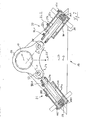
- the drive unit 16 here comprises two hydraulic cylinder units 21, 22, which in the following, despite their complicated structure (see below) are referred to collectively as hydraulic cylinders. They are horizontal and thus located perpendicular to the deflection axis 11. In the neutral position (FIGS. 3, 7), the hydraulic cylinders 21, 22 are arranged symmetrically with respect to one another and symmetrically with respect to a vehicle longitudinal plane 23 intersecting the deflection axis 11.
- the drive unit 16 is movable with the rotor 9 and thus together with the boom 3 transversely to the vehicle 2.
- a responsible for this additional cylinder may be parallel to the guide rail 8 and be provided with a fuse circuit such that the transverse displacement only at angular positions of the boom between Fig. 5 and Fig. 6 is possible to avoid a collision with the cab 17.
- the hydraulic cylinders 21, 22 engage from different directions on levers 24, 25, which are associated with the holder 10.
- the levers 24, 25 are part of a common plate 26, At this the hydraulic cylinders 21, 22 engage in each case via a parallel to the deflection axis 11 Anlenkungsachse 27, 28 with their piston rods 21c, 22c.
- the cylinders 21, 22 At their piston bottom side ends, the cylinders 21, 22 via support axes 29, 30, which are also parallel to the axis 11, pivotally supported on a support 31 within the protective cage 15.
- the connecting lines of the support shafts 29, 30 with the deflection axis 11 form an isosceles triangle (FIG. 7).
- the possibility of movement of the arm 3 about the axis 11 to the right and left is completely symmetrical, so as to allow without modification both editing the right and the left roadside.
- the rearwardly facing position of the boom 3 forms a dynamic or static zero position.
- the working head 4 can be deposited on the loading area 18 in this position. But it is also possible that this represents only a passage position without storage possibility and thus a purely geometric zero position.
- the boom on both sides by at least 90 ° about the axis 11 is pivotable. 1 or the transverse transporting device according to FIG. 2.
- the extension arm 3 can still be pivoted further forward by at least 20 °, ie by at least 110 relative to the zero position °, whereby he then comes in the direction indicated in Fig. 5 and slightly before the front end of the vehicle cross position.
- All swivel positions can be achieved only by appropriate action on the hydraulic cylinders 21, 22 whose end positions limit the swivel angle. Thus, other external stops to limit the swing angle are completely unnecessary.
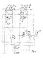
- each hydraulic cylinder 21, 22 consists of two nested cylinders; nevertheless, only three external connections must be provided:
- the holding on the support axes 29, 30 pivotally supported on the carrier 31 outer piston housing 21a and 22a is provided on the piston crown side with a pressure medium connection AR2 and AL2.
- the piston rod 21b or 22b which can be moved in the piston housing 21a, 22a of the outer cylinder at the same time forms the piston housing for an inner piston rod 21c or 22c, which can then act on the articulation axes 27, 28 of the levers 24, 25 of the holder 10.
- the passage channel AR1 or AL1 which connects the piston head of the inner cylinder with that of the outer cylinder.
- This connection is not mandatory, but simplistic. A further external connection could alternatively be provided.
- the force action line 29-27 of the cylinder 21 driving here by pressure during the transition from FIG. 7 to FIG. 5 remains on the vehicle side of the axle 11 during this entire movement and does not cut it.
- a passage through the axis takes place only in the line of action of here passively taken cylinder 22 and is therefore harmless to the high efficiency of power transmission.
- an additional drive 32 for example a hydraulic cylinder, which causes lifting of the boom 3 with the working head 4 manually or automatically upon contact with an obstacle, thereby avoiding damage.
Landscapes
- Life Sciences & Earth Sciences (AREA)
- Environmental Sciences (AREA)
- Harvester Elements (AREA)
- Shovels (AREA)
- Working Measures On Existing Buildindgs (AREA)
Priority Applications (1)
| Application Number | Priority Date | Filing Date | Title |
|---|---|---|---|
| PL06007679T PL1762132T3 (pl) | 2005-04-22 | 2006-04-12 | Urządzenie koszące i/lub tnące |
Applications Claiming Priority (5)
| Application Number | Priority Date | Filing Date | Title |
|---|---|---|---|
| DE200520006541 DE202005006541U1 (de) | 2005-04-22 | 2005-04-22 | Mäh- und/oder Schneidgerät |
| DE200520006539 DE202005006539U1 (de) | 2005-04-22 | 2005-04-22 | Mäh- und/oder Schneidgerät |
| DE102005018987.3A DE102005018987B4 (de) | 2005-04-22 | 2005-04-22 | Mäh- und/oder Schneidgerät |
| DE200520006540 DE202005006540U1 (de) | 2005-04-22 | 2005-04-22 | Mäh- und/oder Schneidgerät |
| DE200520006542 DE202005006542U1 (de) | 2005-04-22 | 2005-04-22 | Mäh- und/oder Schneidgerät |
Publications (2)
| Publication Number | Publication Date |
|---|---|
| EP1762132A1 true EP1762132A1 (fr) | 2007-03-14 |
| EP1762132B1 EP1762132B1 (fr) | 2008-11-12 |
Family
ID=36642786
Family Applications (6)
| Application Number | Title | Priority Date | Filing Date |
|---|---|---|---|
| EP06007680A Expired - Lifetime EP1759572B1 (fr) | 2005-04-22 | 2006-04-12 | Appareil à faucher et/ou couper |
| EP06007677A Expired - Lifetime EP1759571B1 (fr) | 2005-04-22 | 2006-04-12 | Appareil à faucher et/ou couper |
| EP06007679A Expired - Lifetime EP1762132B1 (fr) | 2005-04-22 | 2006-04-12 | Appareil à faucher et/ou couper |
| EP10003552A Expired - Lifetime EP2213156B1 (fr) | 2005-04-22 | 2006-04-12 | Appareil à faucher et/ou couper |
| EP06007689A Expired - Lifetime EP1759573B1 (fr) | 2005-04-22 | 2006-04-12 | Appareil à faucher et/ou couper |
| EP06007678A Expired - Lifetime EP1762131B1 (fr) | 2005-04-22 | 2006-04-12 | Appareil à faucher et/ou couper |
Family Applications Before (2)
| Application Number | Title | Priority Date | Filing Date |
|---|---|---|---|
| EP06007680A Expired - Lifetime EP1759572B1 (fr) | 2005-04-22 | 2006-04-12 | Appareil à faucher et/ou couper |
| EP06007677A Expired - Lifetime EP1759571B1 (fr) | 2005-04-22 | 2006-04-12 | Appareil à faucher et/ou couper |
Family Applications After (3)
| Application Number | Title | Priority Date | Filing Date |
|---|---|---|---|
| EP10003552A Expired - Lifetime EP2213156B1 (fr) | 2005-04-22 | 2006-04-12 | Appareil à faucher et/ou couper |
| EP06007689A Expired - Lifetime EP1759573B1 (fr) | 2005-04-22 | 2006-04-12 | Appareil à faucher et/ou couper |
| EP06007678A Expired - Lifetime EP1762131B1 (fr) | 2005-04-22 | 2006-04-12 | Appareil à faucher et/ou couper |
Country Status (5)
| Country | Link |
|---|---|
| EP (6) | EP1759572B1 (fr) |
| AT (5) | ATE405143T1 (fr) |
| DE (5) | DE502006001368D1 (fr) |
| DK (6) | DK1759572T3 (fr) |
| PL (5) | PL1759573T3 (fr) |
Families Citing this family (6)
| Publication number | Priority date | Publication date | Assignee | Title |
|---|---|---|---|---|
| SE534290C2 (sv) * | 2009-09-15 | 2011-06-28 | Bertil Karlsson | Vertikal redskapsbärare avsedd för motorfordon vid väg- och gatuvägunderhåll |
| FR2966693A1 (fr) * | 2010-10-29 | 2012-05-04 | Calvet | Potence porte-outils pour vehicules notamment agricole. |
| DE202014106218U1 (de) | 2014-12-22 | 2016-03-23 | Herder B.V. | Straßenfahrzeug, das mit einem Mähersystem ausgerüstet ist |
| DE102016122229B4 (de) | 2016-11-18 | 2023-06-01 | MULAG FAHRZEUGWERK Heinz Wössner GmbH & Co. KG | Auslegerarm sowie mit einem solchen Auslegerarm ausgestattetes Ausleger-Arbeitsgerät |
| NL2026977B1 (en) | 2020-11-25 | 2022-07-04 | Herder Bv | Boom system, vehicle and method for cutting vegetation |
| EP4230797B1 (fr) * | 2022-02-18 | 2025-05-21 | Jürgen Stehr | Accessoire pour le brochage et l'épandage de surfaces et appareil de brochage doté d'un tel accessoire |
Citations (3)
| Publication number | Priority date | Publication date | Assignee | Title |
|---|---|---|---|---|
| US3087296A (en) * | 1962-05-15 | 1963-04-30 | John T Cowles | Brush cutter |
| NL9401826A (nl) * | 1994-11-03 | 1996-06-03 | Conver Machines B V | Inrichting voor het dragen van een gereedschap. |
| DE19623391A1 (de) * | 1995-06-12 | 1997-01-16 | Odoardo Guerrieri Gonzaga | Landwirtschaftliches Fahrzeug mit angebautem Huborgan |
Family Cites Families (11)
| Publication number | Priority date | Publication date | Assignee | Title |
|---|---|---|---|---|
| DE3218525C2 (de) * | 1982-05-17 | 1986-01-16 | Gerhard Dücker KG Landmaschinenfabrik, 4424 Stadtlohn | Böschungsmähgerät |
| EP0150975A3 (fr) * | 1984-01-28 | 1987-10-21 | Turner International (Engineering) Limited | Faucheuses |
| DE3709681A1 (de) * | 1986-12-18 | 1988-10-06 | Strautmann & Soehne | Schneidwerk fuer flachsilo-entnahmegeraet |
| DE69912671T2 (de) * | 1998-04-24 | 2004-09-30 | Binger France S.A.R.L. | Geräteunterstützungsvorrichtung insbesondere für Landwirtschaft, Weinbau und Baumgärtnerei |
| US6047531A (en) * | 1999-01-08 | 2000-04-11 | Bryan, Iii; William | Apparatus for cutting brush |
| DE10027133B4 (de) * | 2000-05-31 | 2005-03-03 | Mulag Fahrzeugwerk Heinz Wössner GmbH u. Co KG | Mähgerät mit zwei Mähköpfen |
| ITBO20010595A1 (it) * | 2001-09-27 | 2003-03-27 | Ferri Srl | Dispositivo a braccio idraulico articolato particolarmente per un utensile agricolo |
| DE60205226T2 (de) * | 2002-05-15 | 2006-06-01 | Laserjet S.R.L., Poiana Maggiore | Buschmäherfahrzeug |
| DE10227261B4 (de) * | 2002-06-19 | 2016-02-18 | Gerhard Dücker GmbH & Co. KG Landmaschinenfabrik | Mäh- und/oder Schneidgerät |
| DE20211861U1 (de) * | 2002-08-01 | 2002-11-14 | Gerhard Dücker GmbH & Co. KG Landmaschinenfabrik, 48703 Stadtlohn | Mähgerät |
| DE102004032573A1 (de) | 2004-07-05 | 2006-02-23 | GÖDDE Maschinenbau GmbH | Trägerfahrzeug mit Mähgerät |
-
2006
- 2006-04-12 AT AT06007678T patent/ATE405143T1/de not_active IP Right Cessation
- 2006-04-12 EP EP06007680A patent/EP1759572B1/fr not_active Expired - Lifetime
- 2006-04-12 PL PL06007689T patent/PL1759573T3/pl unknown
- 2006-04-12 DK DK06007680T patent/DK1759572T3/da active
- 2006-04-12 AT AT06007679T patent/ATE413801T1/de active
- 2006-04-12 PL PL06007678T patent/PL1762131T3/pl unknown
- 2006-04-12 PL PL10003552T patent/PL2213156T3/pl unknown
- 2006-04-12 PL PL06007680T patent/PL1759572T3/pl unknown
- 2006-04-12 EP EP06007677A patent/EP1759571B1/fr not_active Expired - Lifetime
- 2006-04-12 DE DE502006001368T patent/DE502006001368D1/de not_active Expired - Lifetime
- 2006-04-12 DE DE502006002048T patent/DE502006002048D1/de not_active Expired - Lifetime
- 2006-04-12 DE DE502006002793T patent/DE502006002793D1/de not_active Expired - Lifetime
- 2006-04-12 EP EP06007679A patent/EP1762132B1/fr not_active Expired - Lifetime
- 2006-04-12 DK DK06007679T patent/DK1762132T3/da active
- 2006-04-12 EP EP10003552A patent/EP2213156B1/fr not_active Expired - Lifetime
- 2006-04-12 DK DK06007689T patent/DK1759573T3/da active
- 2006-04-12 AT AT06007689T patent/ATE397376T1/de active
- 2006-04-12 AT AT06007680T patent/ATE422286T1/de active
- 2006-04-12 DE DE502006000872T patent/DE502006000872D1/de not_active Expired - Lifetime
- 2006-04-12 DK DK06007678T patent/DK1762131T3/da active
- 2006-04-12 EP EP06007689A patent/EP1759573B1/fr not_active Expired - Lifetime
- 2006-04-12 DK DK10003552.6T patent/DK2213156T3/da active
- 2006-04-12 DE DE502006007952T patent/DE502006007952D1/de not_active Expired - Lifetime
- 2006-04-12 EP EP06007678A patent/EP1762131B1/fr not_active Expired - Lifetime
- 2006-04-12 PL PL06007679T patent/PL1762132T3/pl unknown
- 2006-04-12 DK DK06007677.5T patent/DK1759571T3/da active
- 2006-04-12 AT AT06007677T patent/ATE482612T1/de active
Patent Citations (3)
| Publication number | Priority date | Publication date | Assignee | Title |
|---|---|---|---|---|
| US3087296A (en) * | 1962-05-15 | 1963-04-30 | John T Cowles | Brush cutter |
| NL9401826A (nl) * | 1994-11-03 | 1996-06-03 | Conver Machines B V | Inrichting voor het dragen van een gereedschap. |
| DE19623391A1 (de) * | 1995-06-12 | 1997-01-16 | Odoardo Guerrieri Gonzaga | Landwirtschaftliches Fahrzeug mit angebautem Huborgan |
Also Published As
| Publication number | Publication date |
|---|---|
| ATE397376T1 (de) | 2008-06-15 |
| DK1759572T3 (da) | 2009-05-25 |
| DE502006002793D1 (de) | 2009-03-26 |
| DE502006001368D1 (de) | 2008-10-02 |
| EP1762131B1 (fr) | 2008-08-20 |
| EP1759572A1 (fr) | 2007-03-07 |
| ATE482612T1 (de) | 2010-10-15 |
| DK1762132T3 (da) | 2009-02-23 |
| EP2213156A2 (fr) | 2010-08-04 |
| PL1759573T3 (pl) | 2009-04-30 |
| PL1759572T3 (pl) | 2009-09-30 |
| DE502006000872D1 (de) | 2008-07-17 |
| EP1759573B1 (fr) | 2008-06-04 |
| DK2213156T3 (da) | 2013-07-08 |
| PL1762132T3 (pl) | 2009-06-30 |
| DK1759573T3 (da) | 2008-10-13 |
| EP1762131A1 (fr) | 2007-03-14 |
| PL1762131T3 (pl) | 2009-02-27 |
| EP1759571A1 (fr) | 2007-03-07 |
| ATE422286T1 (de) | 2009-02-15 |
| EP2213156B1 (fr) | 2013-04-03 |
| ATE413801T1 (de) | 2008-11-15 |
| EP2213156A3 (fr) | 2011-10-05 |
| EP1759573A1 (fr) | 2007-03-07 |
| DK1759571T3 (da) | 2011-01-24 |
| DE502006002048D1 (de) | 2008-12-24 |
| DE502006007952D1 (de) | 2010-11-11 |
| EP1759571B1 (fr) | 2010-09-29 |
| DK1762131T3 (da) | 2008-12-08 |
| EP1762132B1 (fr) | 2008-11-12 |
| PL2213156T3 (pl) | 2013-11-29 |
| EP1759572B1 (fr) | 2009-02-11 |
| ATE405143T1 (de) | 2008-09-15 |
Similar Documents
| Publication | Publication Date | Title |
|---|---|---|
| EP1813730A2 (fr) | Chargeur frontal et cabine pour tracteur | |
| EP0073360B1 (fr) | Faucheuse | |
| DE3439048A1 (de) | Kraftheber fuer ein hubgeraet | |
| DE19534695C2 (de) | An einem Schlepper ansetzbares Heckmähwerk | |
| DE202004011990U1 (de) | Umschlaggerät | |
| EP1762132B1 (fr) | Appareil à faucher et/ou couper | |
| EP1932414A1 (fr) | Faucheuse destinée à l'agencement frontal sur un véhicule agricole | |
| EP4028599B1 (fr) | Élément de préhension | |
| DE102005018987B4 (de) | Mäh- und/oder Schneidgerät | |
| EP1378157B1 (fr) | Dispositif pour faucher et/ou couper | |
| EP3266292B1 (fr) | Outil agricole tracté et agricole et attelage comprenant un tel outil tracté | |
| EP0545351B1 (fr) | Appareil porteur pour un outil de travail | |
| DE3106929C2 (de) | Anbau-Frontmäher mit hin- und hergehenden Mähmessern | |
| EP3005853B1 (fr) | Outil agricole et procédé de fonctionnement d'un outil agricole | |
| EP3323283A1 (fr) | Bras ainsi qu'un appareil de travail à bras muni d'un tel bras | |
| DE202005006541U1 (de) | Mäh- und/oder Schneidgerät | |
| EP0846411A1 (fr) | Véhicule agricole pour distribuer de l'ensilage aux animaux | |
| EP4491806B1 (fr) | Chargeur frontal, véhicule de travail et système de véhicule de travail | |
| DE9414597U1 (de) | Gezogene Mähmaschine | |
| EP4252503B1 (fr) | Faucheuse agricole pouvant fonctionner en poussée | |
| EP3598882A1 (fr) | Accessoire agricole | |
| DE202012004683U1 (de) | Landmaschine | |
| EP3669630B1 (fr) | Unité de roue de support pour un engin d'abattage-façonnage agricole | |
| DE2447921A1 (de) | Vorrichtung zum raeumen von flaechen, insbesondere forstflaechen | |
| DE202023002870U1 (de) | Frontlader, Arbeitsfahrzeug und Arbeitsfahrzeugsystem |
Legal Events
| Date | Code | Title | Description |
|---|---|---|---|
| PUAI | Public reference made under article 153(3) epc to a published international application that has entered the european phase |
Free format text: ORIGINAL CODE: 0009012 |
|
| AK | Designated contracting states |
Kind code of ref document: A1 Designated state(s): AT BE BG CH CY CZ DE DK EE ES FI FR GB GR HU IE IS IT LI LT LU LV MC NL PL PT RO SE SI SK TR |
|
| AX | Request for extension of the european patent |
Extension state: AL BA HR MK YU |
|
| 17P | Request for examination filed |
Effective date: 20070510 |
|
| 17Q | First examination report despatched |
Effective date: 20070611 |
|
| AKX | Designation fees paid |
Designated state(s): AT BE BG CH CY CZ DE DK EE ES FI FR GB GR HU IE IS IT LI LT LU LV MC NL PL PT RO SE SI SK TR |
|
| GRAP | Despatch of communication of intention to grant a patent |
Free format text: ORIGINAL CODE: EPIDOSNIGR1 |
|
| GRAS | Grant fee paid |
Free format text: ORIGINAL CODE: EPIDOSNIGR3 |
|
| GRAA | (expected) grant |
Free format text: ORIGINAL CODE: 0009210 |
|
| AK | Designated contracting states |
Kind code of ref document: B1 Designated state(s): AT BE BG CH CY CZ DE DK EE ES FI FR GB GR HU IE IS IT LI LT LU LV MC NL PL PT RO SE SI SK TR |
|
| REG | Reference to a national code |
Ref country code: GB Ref legal event code: FG4D Free format text: NOT ENGLISH |
|
| REG | Reference to a national code |
Ref country code: CH Ref legal event code: EP |
|
| REG | Reference to a national code |
Ref country code: IE Ref legal event code: FG4D Free format text: LANGUAGE OF EP DOCUMENT: GERMAN |
|
| REF | Corresponds to: |
Ref document number: 502006002048 Country of ref document: DE Date of ref document: 20081224 Kind code of ref document: P |
|
| REG | Reference to a national code |
Ref country code: DK Ref legal event code: T3 |
|
| LTIE | Lt: invalidation of european patent or patent extension |
Effective date: 20081112 |
|
| PG25 | Lapsed in a contracting state [announced via postgrant information from national office to epo] |
Ref country code: ES Free format text: LAPSE BECAUSE OF FAILURE TO SUBMIT A TRANSLATION OF THE DESCRIPTION OR TO PAY THE FEE WITHIN THE PRESCRIBED TIME-LIMIT Effective date: 20090223 Ref country code: LT Free format text: LAPSE BECAUSE OF FAILURE TO SUBMIT A TRANSLATION OF THE DESCRIPTION OR TO PAY THE FEE WITHIN THE PRESCRIBED TIME-LIMIT Effective date: 20081112 |
|
| PG25 | Lapsed in a contracting state [announced via postgrant information from national office to epo] |
Ref country code: SI Free format text: LAPSE BECAUSE OF FAILURE TO SUBMIT A TRANSLATION OF THE DESCRIPTION OR TO PAY THE FEE WITHIN THE PRESCRIBED TIME-LIMIT Effective date: 20081112 Ref country code: LV Free format text: LAPSE BECAUSE OF FAILURE TO SUBMIT A TRANSLATION OF THE DESCRIPTION OR TO PAY THE FEE WITHIN THE PRESCRIBED TIME-LIMIT Effective date: 20081112 Ref country code: IS Free format text: LAPSE BECAUSE OF FAILURE TO SUBMIT A TRANSLATION OF THE DESCRIPTION OR TO PAY THE FEE WITHIN THE PRESCRIBED TIME-LIMIT Effective date: 20090312 Ref country code: FI Free format text: LAPSE BECAUSE OF FAILURE TO SUBMIT A TRANSLATION OF THE DESCRIPTION OR TO PAY THE FEE WITHIN THE PRESCRIBED TIME-LIMIT Effective date: 20081112 |
|
| REG | Reference to a national code |
Ref country code: PL Ref legal event code: T3 |
|
| REG | Reference to a national code |
Ref country code: IE Ref legal event code: FD4D |
|
| PG25 | Lapsed in a contracting state [announced via postgrant information from national office to epo] |
Ref country code: IE Free format text: LAPSE BECAUSE OF FAILURE TO SUBMIT A TRANSLATION OF THE DESCRIPTION OR TO PAY THE FEE WITHIN THE PRESCRIBED TIME-LIMIT Effective date: 20081112 Ref country code: RO Free format text: LAPSE BECAUSE OF FAILURE TO SUBMIT A TRANSLATION OF THE DESCRIPTION OR TO PAY THE FEE WITHIN THE PRESCRIBED TIME-LIMIT Effective date: 20081112 Ref country code: EE Free format text: LAPSE BECAUSE OF FAILURE TO SUBMIT A TRANSLATION OF THE DESCRIPTION OR TO PAY THE FEE WITHIN THE PRESCRIBED TIME-LIMIT Effective date: 20081112 Ref country code: BG Free format text: LAPSE BECAUSE OF FAILURE TO SUBMIT A TRANSLATION OF THE DESCRIPTION OR TO PAY THE FEE WITHIN THE PRESCRIBED TIME-LIMIT Effective date: 20090212 |
|
| PG25 | Lapsed in a contracting state [announced via postgrant information from national office to epo] |
Ref country code: PT Free format text: LAPSE BECAUSE OF FAILURE TO SUBMIT A TRANSLATION OF THE DESCRIPTION OR TO PAY THE FEE WITHIN THE PRESCRIBED TIME-LIMIT Effective date: 20090413 Ref country code: CZ Free format text: LAPSE BECAUSE OF FAILURE TO SUBMIT A TRANSLATION OF THE DESCRIPTION OR TO PAY THE FEE WITHIN THE PRESCRIBED TIME-LIMIT Effective date: 20081112 Ref country code: SE Free format text: LAPSE BECAUSE OF FAILURE TO SUBMIT A TRANSLATION OF THE DESCRIPTION OR TO PAY THE FEE WITHIN THE PRESCRIBED TIME-LIMIT Effective date: 20090212 |
|
| PLBE | No opposition filed within time limit |
Free format text: ORIGINAL CODE: 0009261 |
|
| STAA | Information on the status of an ep patent application or granted ep patent |
Free format text: STATUS: NO OPPOSITION FILED WITHIN TIME LIMIT |
|
| PG25 | Lapsed in a contracting state [announced via postgrant information from national office to epo] |
Ref country code: SK Free format text: LAPSE BECAUSE OF FAILURE TO SUBMIT A TRANSLATION OF THE DESCRIPTION OR TO PAY THE FEE WITHIN THE PRESCRIBED TIME-LIMIT Effective date: 20081112 |
|
| 26N | No opposition filed |
Effective date: 20090813 |
|
| REG | Reference to a national code |
Ref country code: FR Ref legal event code: ST Effective date: 20091231 |
|
| PG25 | Lapsed in a contracting state [announced via postgrant information from national office to epo] |
Ref country code: MC Free format text: LAPSE BECAUSE OF NON-PAYMENT OF DUE FEES Effective date: 20090430 Ref country code: FR Free format text: LAPSE BECAUSE OF NON-PAYMENT OF DUE FEES Effective date: 20091222 |
|
| PG25 | Lapsed in a contracting state [announced via postgrant information from national office to epo] |
Ref country code: GR Free format text: LAPSE BECAUSE OF FAILURE TO SUBMIT A TRANSLATION OF THE DESCRIPTION OR TO PAY THE FEE WITHIN THE PRESCRIBED TIME-LIMIT Effective date: 20090213 |
|
| REG | Reference to a national code |
Ref country code: CH Ref legal event code: PL |
|
| GBPC | Gb: european patent ceased through non-payment of renewal fee |
Effective date: 20100412 |
|
| PG25 | Lapsed in a contracting state [announced via postgrant information from national office to epo] |
Ref country code: CH Free format text: LAPSE BECAUSE OF NON-PAYMENT OF DUE FEES Effective date: 20100430 Ref country code: LI Free format text: LAPSE BECAUSE OF NON-PAYMENT OF DUE FEES Effective date: 20100430 |
|
| PG25 | Lapsed in a contracting state [announced via postgrant information from national office to epo] |
Ref country code: GB Free format text: LAPSE BECAUSE OF NON-PAYMENT OF DUE FEES Effective date: 20100412 Ref country code: IT Free format text: LAPSE BECAUSE OF FAILURE TO SUBMIT A TRANSLATION OF THE DESCRIPTION OR TO PAY THE FEE WITHIN THE PRESCRIBED TIME-LIMIT Effective date: 20081112 |
|
| PG25 | Lapsed in a contracting state [announced via postgrant information from national office to epo] |
Ref country code: LU Free format text: LAPSE BECAUSE OF NON-PAYMENT OF DUE FEES Effective date: 20090412 |
|
| PG25 | Lapsed in a contracting state [announced via postgrant information from national office to epo] |
Ref country code: HU Free format text: LAPSE BECAUSE OF FAILURE TO SUBMIT A TRANSLATION OF THE DESCRIPTION OR TO PAY THE FEE WITHIN THE PRESCRIBED TIME-LIMIT Effective date: 20090513 |
|
| PG25 | Lapsed in a contracting state [announced via postgrant information from national office to epo] |
Ref country code: TR Free format text: LAPSE BECAUSE OF FAILURE TO SUBMIT A TRANSLATION OF THE DESCRIPTION OR TO PAY THE FEE WITHIN THE PRESCRIBED TIME-LIMIT Effective date: 20081112 |
|
| PG25 | Lapsed in a contracting state [announced via postgrant information from national office to epo] |
Ref country code: CY Free format text: LAPSE BECAUSE OF FAILURE TO SUBMIT A TRANSLATION OF THE DESCRIPTION OR TO PAY THE FEE WITHIN THE PRESCRIBED TIME-LIMIT Effective date: 20081112 |
|
| PGFP | Annual fee paid to national office [announced via postgrant information from national office to epo] |
Ref country code: DE Payment date: 20241023 Year of fee payment: 19 |
|
| PGFP | Annual fee paid to national office [announced via postgrant information from national office to epo] |
Ref country code: NL Payment date: 20250428 Year of fee payment: 20 |
|
| PGFP | Annual fee paid to national office [announced via postgrant information from national office to epo] |
Ref country code: DK Payment date: 20250428 Year of fee payment: 20 |
|
| PGFP | Annual fee paid to national office [announced via postgrant information from national office to epo] |
Ref country code: BE Payment date: 20250429 Year of fee payment: 20 |
|
| PGFP | Annual fee paid to national office [announced via postgrant information from national office to epo] |
Ref country code: AT Payment date: 20250422 Year of fee payment: 20 |
|
| PGFP | Annual fee paid to national office [announced via postgrant information from national office to epo] |
Ref country code: PL Payment date: 20250730 Year of fee payment: 20 |
|
| REG | Reference to a national code |
Ref country code: DE Ref legal event code: R119 Ref document number: 502006002048 Country of ref document: DE |
|
| PG25 | Lapsed in a contracting state [announced via postgrant information from national office to epo] |
Ref country code: DE Free format text: LAPSE BECAUSE OF NON-PAYMENT OF DUE FEES Effective date: 20251104 |
|
| REG | Reference to a national code |
Ref country code: DK Ref legal event code: EUP Expiry date: 20260412 |
|
| REG | Reference to a national code |
Ref country code: NL Ref legal event code: MK Effective date: 20260411 |