EP1762405B1 - Suspension de véhicule - Google Patents
Suspension de véhicule Download PDFInfo
- Publication number
- EP1762405B1 EP1762405B1 EP06018164A EP06018164A EP1762405B1 EP 1762405 B1 EP1762405 B1 EP 1762405B1 EP 06018164 A EP06018164 A EP 06018164A EP 06018164 A EP06018164 A EP 06018164A EP 1762405 B1 EP1762405 B1 EP 1762405B1
- Authority
- EP
- European Patent Office
- Prior art keywords
- seat
- axle
- recess
- insert
- trailing arm
- Prior art date
- Legal status (The legal status is an assumption and is not a legal conclusion. Google has not performed a legal analysis and makes no representation as to the accuracy of the status listed.)
- Active
Links
Images

Classifications
-
- B—PERFORMING OPERATIONS; TRANSPORTING
- B60—VEHICLES IN GENERAL
- B60G—VEHICLE SUSPENSION ARRANGEMENTS
- B60G11/00—Resilient suspensions characterised by arrangement, location or kind of springs
- B60G11/02—Resilient suspensions characterised by arrangement, location or kind of springs having leaf springs only
- B60G11/10—Resilient suspensions characterised by arrangement, location or kind of springs having leaf springs only characterised by means specially adapted for attaching the spring to axle or sprung part of the vehicle
- B60G11/113—Mountings on the axle
-
- B—PERFORMING OPERATIONS; TRANSPORTING
- B60—VEHICLES IN GENERAL
- B60G—VEHICLE SUSPENSION ARRANGEMENTS
- B60G11/00—Resilient suspensions characterised by arrangement, location or kind of springs
- B60G11/02—Resilient suspensions characterised by arrangement, location or kind of springs having leaf springs only
- B60G11/04—Resilient suspensions characterised by arrangement, location or kind of springs having leaf springs only arranged substantially parallel to the longitudinal axis of the vehicle
-
- B—PERFORMING OPERATIONS; TRANSPORTING
- B60—VEHICLES IN GENERAL
- B60G—VEHICLE SUSPENSION ARRANGEMENTS
- B60G9/00—Resilient suspensions of a rigid axle or axle housing for two or more wheels
- B60G9/003—Resilient suspensions of a rigid axle or axle housing for two or more wheels the axle being rigidly connected to a trailing guiding device
-
- B—PERFORMING OPERATIONS; TRANSPORTING
- B60—VEHICLES IN GENERAL
- B60G—VEHICLE SUSPENSION ARRANGEMENTS
- B60G2200/00—Indexing codes relating to suspension types
- B60G2200/30—Rigid axle suspensions
- B60G2200/31—Rigid axle suspensions with two trailing arms rigidly connected to the axle
-
- B—PERFORMING OPERATIONS; TRANSPORTING
- B60—VEHICLES IN GENERAL
- B60G—VEHICLE SUSPENSION ARRANGEMENTS
- B60G2202/00—Indexing codes relating to the type of spring, damper or actuator
- B60G2202/10—Type of spring
- B60G2202/11—Leaf spring
- B60G2202/112—Leaf spring longitudinally arranged
-
- B—PERFORMING OPERATIONS; TRANSPORTING
- B60—VEHICLES IN GENERAL
- B60G—VEHICLE SUSPENSION ARRANGEMENTS
- B60G2204/00—Indexing codes related to suspensions per se or to auxiliary parts
- B60G2204/10—Mounting of suspension elements
- B60G2204/12—Mounting of springs or dampers
- B60G2204/122—Mounting of torsion springs
-
- B—PERFORMING OPERATIONS; TRANSPORTING
- B60—VEHICLES IN GENERAL
- B60G—VEHICLE SUSPENSION ARRANGEMENTS
- B60G2204/00—Indexing codes related to suspensions per se or to auxiliary parts
- B60G2204/40—Auxiliary suspension parts; Adjustment of suspensions
- B60G2204/43—Fittings, brackets or knuckles
- B60G2204/4306—Bracket or knuckle for rigid axles, e.g. for clamping
-
- B—PERFORMING OPERATIONS; TRANSPORTING
- B60—VEHICLES IN GENERAL
- B60G—VEHICLE SUSPENSION ARRANGEMENTS
- B60G2206/00—Indexing codes related to the manufacturing of suspensions: constructional features, the materials used, procedures or tools
- B60G2206/01—Constructional features of suspension elements, e.g. arms, dampers, springs
- B60G2206/80—Manufacturing procedures
- B60G2206/81—Shaping
- B60G2206/8101—Shaping by casting
-
- B—PERFORMING OPERATIONS; TRANSPORTING
- B60—VEHICLES IN GENERAL
- B60G—VEHICLE SUSPENSION ARRANGEMENTS
- B60G2206/00—Indexing codes related to the manufacturing of suspensions: constructional features, the materials used, procedures or tools
- B60G2206/01—Constructional features of suspension elements, e.g. arms, dampers, springs
- B60G2206/80—Manufacturing procedures
- B60G2206/82—Joining
- B60G2206/8201—Joining by welding
Definitions
- This invention relates to vehicle suspensions, and is particularly, but not necessarily exclusively, concerned with medium weight lorries with an intended maximum axle weight of 9.5 tonnes.
- Lorries of the type referred to frequently employ air spring suspension systems where an air spring is positioned on a trailing arm attached to an axle, and where, ordinarily, the axle is of pressed steel construction to form a casing.
- Another problem with a welded seat is that a considerable difficulty is encountered in positioning it on the axle to hold a trailing arm in the correct alignment, particularly when, as is currently so, the trailing arms taper in both the horizontal and vertical planes.
- US 2 280 347 discloses a seat for trailling arm having a secess to secure the axle and a second one to secure the trailing arm.
- the object of the present invention is to provide a vehicle suspension that avoids those disadvantages mentioned above.
- a vehicle suspension comprises an axle and at least one trailing arm, there being a seat for the or each trailing arm, the or each seat having a primary recess in which the axle is located, the primary recess having a transverse secondary recess in which an insert is located, the insert being positively secured in the primary recess, and having end sections extending beyond the edges of the primary recess, that are positively secured to the adjacent walls of the axle.
- a seat suitable for use in a vehicle suspension system comprises a primary recess in one (lower) surface of the seat, a secondary transverse recess in the primary recess, and an insert bent into generally U-shaped configuration, said insert being fitted into the secondary recess and there secured by welding, with end sections of the insert extending beyond the edges of the primary recess.
- the seat is a solid cast or machined weldable steel component, and is formed with a longitudinal recess to create an inner face with dependent side walls across which the secondary recess extends.
- the insert is formed from relatively thin sheet weldable material to be flexible or resilient that is bent into the generally U-shape to fit in the transverse recess.
- top and bottom clamp members can be provided with U-bolts extending around the top member, with the legs of the U-bolts extending through co-operating holes in the trailing arm seat and the bottom clamp member with securing nuts engaging threaded end sections of the arms of the U-bolts.
- Figure 1 shows part of a vehicle axle and suspension system where the axle casing 1 supports a trailing arm 2 that supports an air spring (not shown) of an air spring suspension, or to which is attached a hydraulic strut (not shown) of a hydraulic suspension system.
- a seat 3 is fitted to the axle casing 1 and the trailing arm 2 held secure to the seat by U-bolts 4 bolted to a bottom clamp member 5 lying below the axle casing 1 and extending over a top clamp 6 sat on the axle casing 1.
- stud-like location means can be provided on the under surface of the trailing arm 2 to engage in a strategically located recess in the upper face of the seat.
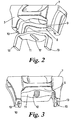
- the seat 3 is formed as a cast or machined component of weldable steel.
- the seat has a flat upper surface 7, and the lower surface 8 shaped into a primary longitudinal (in the direction of the vehicle longitudinal axis) recess 9 to allow the seat to fit on to the upper surface of the axle casing 1.
- a primary longitudinal recess is a secondary transverse recess 10, to receive an insert 11 in the form of a thin sheet of weldable metal, suitably bent into a U-shape to fit in the second recess 10.
- the insert 11 is relatively flexible or resilient to ensure that it is a reasonably close fit in the second recess.
- the insert is provided with a through hole 12 which, and as is illustrated in Figure 3 , is filled with weld metal, the length of the insert being such that when secured to the seat, end sections 13 of the insert protrude beyond the lower faces 14 of the sides 15 of the seat.
- the insert 11, and particularly the protruding sections 13, lie in close, if not abutting, proximity to the sides of the axle casing, and the seat 3 is secured in place by welding the protruding sections 13 of the insert 11 to the axle casing sides.
- the invention ensures a substantial elimination of fitting problems associated with conventional trailing arms of vehicle suspension systems, and by welding an insert into a recess in the seat for the trailing arm, and welding the insert to the casing, there is the substantial elimination of stressing of the welds during use, as a consequence of the insert being relatively resilient or flexible, allowing a limited movement between the trailing arm seat and the axle casing.
Landscapes
- Engineering & Computer Science (AREA)
- Mechanical Engineering (AREA)
- Vehicle Body Suspensions (AREA)
- Transition And Organic Metals Composition Catalysts For Addition Polymerization (AREA)
Claims (7)
- Suspension de véhicule comprenant un essieu (1) et au moins un bras tiré (2), où il y a un siège (3) pour le ou chaque bras tiré, le ou chaque siège (3) ayant un évidement primaire dans lequel se trouve l'essieu, l'évidement primaire ayant un évidement secondaire transversal dans lequel se trouve un insert, l'insert étant positivement fixé dans l'évidement primaire, et ayant des parties d'extrémité s'étendant au-delà des bords de l'évidement primaire, qui sont positivement fixées aux parois adjacentes de l'essieu.
- Siège (3) destiné à être utilisé dans un système de suspension de véhicule comprenant un évidement primaire dans une surface inférieure du siège, un évidement transversal secondaire (10) dans l'évidement primaire, et un insert (11) plié dans une configuration généralement en forme de U, ledit insert étant monté dans l'évidement secondaire (10) et y étant fixé par soudure, avec des parties d'extrémité de l'insert s'étendant au-delà des bords de l'évidement primaire.
- Siège selon la revendication 2, dans lequel il s'agit d'un composant en acier soudable moulé solide ou usiné constitué d'un évidement primaire longitudinal pour former une face intérieure avec des parois latérales dépendantes sur lesquelles l'évidement secondaire s'étend.
- Siège selon la revendication 3, dans lequel l'insert est formé de tôles d'acier soudables relativement fines pour être élastique ou flexible, et plié dans une forme généralement en U pour entrer dans l'évidement secondaire, avec des parties d'extrémité s'étendant au-delà des bords de l'évidement primaire.
- Siège selon l'une quelconque des revendications 2 à 4, dans lequel, pour fixer l'insert dans l'évidement secondaire, une soudure est fournie entre l'insert et le fond de l'évidement primaire.
- Suspension de véhicule selon la revendication 1, ayant un siège selon l'une quelconque des revendications 2 à 5, dans laquelle le siège est fixé au carter d'essieu par des soudures fournies entre les parties d'extrémité de l'insert et le carter d'essieu.
- Suspension de véhicule et siège, sensiblement comme cela a été décrit ci-avant en référence respectivement à la figure 1 et aux figures 2 et 3 des dessins annexés.
Applications Claiming Priority (1)
| Application Number | Priority Date | Filing Date | Title |
|---|---|---|---|
| GBGB0518300.9A GB0518300D0 (en) | 2005-09-08 | 2005-09-08 | Vehicle suspensions |
Publications (2)
| Publication Number | Publication Date |
|---|---|
| EP1762405A1 EP1762405A1 (fr) | 2007-03-14 |
| EP1762405B1 true EP1762405B1 (fr) | 2010-08-11 |
Family
ID=35221090
Family Applications (1)
| Application Number | Title | Priority Date | Filing Date |
|---|---|---|---|
| EP06018164A Active EP1762405B1 (fr) | 2005-09-08 | 2006-08-31 | Suspension de véhicule |
Country Status (9)
| Country | Link |
|---|---|
| US (1) | US7540514B2 (fr) |
| EP (1) | EP1762405B1 (fr) |
| AT (1) | ATE477135T1 (fr) |
| AU (1) | AU2006207872B2 (fr) |
| CA (1) | CA2559106C (fr) |
| DE (1) | DE602006016051D1 (fr) |
| ES (1) | ES2353241T3 (fr) |
| GB (1) | GB0518300D0 (fr) |
| MX (1) | MXPA06010158A (fr) |
Families Citing this family (7)
| Publication number | Priority date | Publication date | Assignee | Title |
|---|---|---|---|---|
| DE102010009304A1 (de) | 2010-02-25 | 2011-08-25 | MAN Truck & Bus AG, 80995 | Vorrichtung zur Anbindung eines Federelements an einer Nutzfahrzeugachse |
| US8322736B2 (en) * | 2011-02-18 | 2012-12-04 | Honda Motor Co., Ltd. | Swing arm assembly |
| US10237565B2 (en) | 2011-08-01 | 2019-03-19 | Qualcomm Incorporated | Coding parameter sets for various dimensions in video coding |
| US9050870B2 (en) | 2012-05-30 | 2015-06-09 | Hendrickson Usa, L.L.C. | Energy storing suspension components having retention recesses |
| US8827289B2 (en) * | 2012-08-06 | 2014-09-09 | Hendrickson Usa, L.L.C. | Reduced weight axle mounting assembly for vehicle suspension systems |
| US11273680B2 (en) | 2020-04-10 | 2022-03-15 | Dana Heavy Vehicle Systems Group, Llc | Suspension system |
| US12594801B2 (en) | 2023-09-22 | 2026-04-07 | Lippert Components, Inc. | Axle suspension system |
Family Cites Families (11)
| Publication number | Priority date | Publication date | Assignee | Title |
|---|---|---|---|---|
| GB530761A (en) * | 1939-07-03 | 1940-12-19 | Vauxhall Motors Ltd | Improvements relating to motor vehicle suspension systems |
| US2907579A (en) * | 1956-06-13 | 1959-10-06 | Neway Equipment Co | Axle mounting for running gear for automotive vehicles |
| US3751021A (en) * | 1971-10-12 | 1973-08-07 | Dayton Steel Foundry Co | Leaf spring clamp and support |
| US4371190A (en) * | 1980-01-28 | 1983-02-01 | Turner Quick-Lift Corporation | Axle suspension system |
| US4801129A (en) * | 1987-01-20 | 1989-01-31 | Ford Motor Company | Leaf spring clamp with attachment means |
| US4895350A (en) * | 1988-08-01 | 1990-01-23 | A. O. Smith Corporation | Axle mount construction for a fiber reinforced resin leaf spring |
| US5950971A (en) * | 1996-06-28 | 1999-09-14 | The Boler Company | Assembly for and method of mounting a suspension member to an axle housing |
| US5921570A (en) * | 1996-11-21 | 1999-07-13 | The Boler Company | Weld-on axle bracket with U-bolt connection |
| US20010052685A1 (en) * | 2000-06-16 | 2001-12-20 | Svartz Bjorn O. | Suspension |
| US6945548B2 (en) * | 2001-02-26 | 2005-09-20 | Hendrickson Usa, L.L.C. | Air spring and air spring mounting assembly |
| US6959932B2 (en) * | 2002-11-04 | 2005-11-01 | Volvo Trucks North America, Inc. | Electronic height control |
-
2005
- 2005-09-08 GB GBGB0518300.9A patent/GB0518300D0/en not_active Ceased
-
2006
- 2006-08-31 ES ES06018164T patent/ES2353241T3/es active Active
- 2006-08-31 EP EP06018164A patent/EP1762405B1/fr active Active
- 2006-08-31 DE DE602006016051T patent/DE602006016051D1/de active Active
- 2006-08-31 AT AT06018164T patent/ATE477135T1/de not_active IP Right Cessation
- 2006-09-05 CA CA2559106A patent/CA2559106C/fr active Active
- 2006-09-06 US US11/470,391 patent/US7540514B2/en active Active
- 2006-09-07 MX MXPA06010158A patent/MXPA06010158A/es active IP Right Grant
- 2006-09-07 AU AU2006207872A patent/AU2006207872B2/en not_active Ceased
Also Published As
| Publication number | Publication date |
|---|---|
| ATE477135T1 (de) | 2010-08-15 |
| CA2559106C (fr) | 2014-01-28 |
| US7540514B2 (en) | 2009-06-02 |
| MXPA06010158A (es) | 2007-04-19 |
| AU2006207872A1 (en) | 2007-03-22 |
| DE602006016051D1 (de) | 2010-09-23 |
| AU2006207872B2 (en) | 2011-04-07 |
| ES2353241T3 (es) | 2011-02-28 |
| EP1762405A1 (fr) | 2007-03-14 |
| CA2559106A1 (fr) | 2007-03-08 |
| US20070210549A1 (en) | 2007-09-13 |
| GB0518300D0 (en) | 2005-10-19 |
Similar Documents
| Publication | Publication Date | Title |
|---|---|---|
| CN1726139B (zh) | 铸造或锻造的悬架拖臂以及具有该悬架拖臂的悬架组件 | |
| CN1876413B (zh) | 悬架拖臂和重型车辆悬架组件 | |
| US9493048B2 (en) | Motor vehicle axle suspension with longitudinal leaf spring | |
| US9050875B2 (en) | Trailing arm yoke suspension with brake actuator clearance | |
| EP2525989B1 (fr) | Liaison robuste entre un essieu et une poutre | |
| EP0854057A2 (fr) | Essieu directeur | |
| CA1121998A (fr) | Mecanisme et methode d'alignement d'essieux rigides | |
| US4566719A (en) | Spaced axle-to-beam connection for suspension of the rigid beam type | |
| KR20110074723A (ko) | 구조적 i-빔 자동차 현가 암 | |
| US20050253351A1 (en) | Preloaded suspension bracket assembly for axle housing | |
| CN112566800A (zh) | 具有增强特征和连接节点的车辆悬架部件 | |
| US6733020B2 (en) | Suspension trailing arm | |
| CN113784854B (zh) | 悬架总成 | |
| EP1762405B1 (fr) | Suspension de véhicule | |
| EP0055761B1 (fr) | Bogie de chemin de fer adaptable pour recevoir une suspension primaire commune et des paliers variables | |
| US8006990B1 (en) | Spring hanger and method for attachment | |
| WO2010131949A1 (fr) | Support de montage de bras oscillant | |
| CN111278669A (zh) | 加工成形的车轴座组件 | |
| JPH09193640A (ja) | サスペンション | |
| CN107089110A (zh) | 一种汽车扭梁悬架后轴总成 | |
| CN120942381A (zh) | 抗蛇行减振器安装结构 | |
| CN111032381A (zh) | 具有用于横向引导连杆的插入件的机动车辆横梁系统 |
Legal Events
| Date | Code | Title | Description |
|---|---|---|---|
| PUAI | Public reference made under article 153(3) epc to a published international application that has entered the european phase |
Free format text: ORIGINAL CODE: 0009012 |
|
| AK | Designated contracting states |
Kind code of ref document: A1 Designated state(s): AT BE BG CH CY CZ DE DK EE ES FI FR GB GR HU IE IS IT LI LT LU LV MC NL PL PT RO SE SI SK TR |
|
| AX | Request for extension of the european patent |
Extension state: AL BA HR MK YU |
|
| 17P | Request for examination filed |
Effective date: 20070215 |
|
| AKX | Designation fees paid |
Designated state(s): AT BE BG CH CY CZ DE DK EE ES FI FR GB GR HU IE IS IT LI LT LU LV MC NL PL PT RO SE SI SK TR |
|
| GRAP | Despatch of communication of intention to grant a patent |
Free format text: ORIGINAL CODE: EPIDOSNIGR1 |
|
| GRAS | Grant fee paid |
Free format text: ORIGINAL CODE: EPIDOSNIGR3 |
|
| GRAA | (expected) grant |
Free format text: ORIGINAL CODE: 0009210 |
|
| AK | Designated contracting states |
Kind code of ref document: B1 Designated state(s): AT BE BG CH CY CZ DE DK EE ES FI FR GB GR HU IE IS IT LI LT LU LV MC NL PL PT RO SE SI SK TR |
|
| REG | Reference to a national code |
Ref country code: GB Ref legal event code: FG4D |
|
| REG | Reference to a national code |
Ref country code: CH Ref legal event code: EP |
|
| REG | Reference to a national code |
Ref country code: IE Ref legal event code: FG4D |
|
| REF | Corresponds to: |
Ref document number: 602006016051 Country of ref document: DE Date of ref document: 20100923 Kind code of ref document: P |
|
| REG | Reference to a national code |
Ref country code: NL Ref legal event code: VDEP Effective date: 20100811 |
|
| LTIE | Lt: invalidation of european patent or patent extension |
Effective date: 20100811 |
|
| PG25 | Lapsed in a contracting state [announced via postgrant information from national office to epo] |
Ref country code: AT Free format text: LAPSE BECAUSE OF FAILURE TO SUBMIT A TRANSLATION OF THE DESCRIPTION OR TO PAY THE FEE WITHIN THE PRESCRIBED TIME-LIMIT Effective date: 20100811 Ref country code: NL Free format text: LAPSE BECAUSE OF FAILURE TO SUBMIT A TRANSLATION OF THE DESCRIPTION OR TO PAY THE FEE WITHIN THE PRESCRIBED TIME-LIMIT Effective date: 20100811 Ref country code: FI Free format text: LAPSE BECAUSE OF FAILURE TO SUBMIT A TRANSLATION OF THE DESCRIPTION OR TO PAY THE FEE WITHIN THE PRESCRIBED TIME-LIMIT Effective date: 20100811 Ref country code: LT Free format text: LAPSE BECAUSE OF FAILURE TO SUBMIT A TRANSLATION OF THE DESCRIPTION OR TO PAY THE FEE WITHIN THE PRESCRIBED TIME-LIMIT Effective date: 20100811 |
|
| PG25 | Lapsed in a contracting state [announced via postgrant information from national office to epo] |
Ref country code: CY Free format text: LAPSE BECAUSE OF FAILURE TO SUBMIT A TRANSLATION OF THE DESCRIPTION OR TO PAY THE FEE WITHIN THE PRESCRIBED TIME-LIMIT Effective date: 20100811 Ref country code: SI Free format text: LAPSE BECAUSE OF FAILURE TO SUBMIT A TRANSLATION OF THE DESCRIPTION OR TO PAY THE FEE WITHIN THE PRESCRIBED TIME-LIMIT Effective date: 20100811 Ref country code: PT Free format text: LAPSE BECAUSE OF FAILURE TO SUBMIT A TRANSLATION OF THE DESCRIPTION OR TO PAY THE FEE WITHIN THE PRESCRIBED TIME-LIMIT Effective date: 20101213 Ref country code: PL Free format text: LAPSE BECAUSE OF FAILURE TO SUBMIT A TRANSLATION OF THE DESCRIPTION OR TO PAY THE FEE WITHIN THE PRESCRIBED TIME-LIMIT Effective date: 20100811 Ref country code: IS Free format text: LAPSE BECAUSE OF FAILURE TO SUBMIT A TRANSLATION OF THE DESCRIPTION OR TO PAY THE FEE WITHIN THE PRESCRIBED TIME-LIMIT Effective date: 20101211 Ref country code: BG Free format text: LAPSE BECAUSE OF FAILURE TO SUBMIT A TRANSLATION OF THE DESCRIPTION OR TO PAY THE FEE WITHIN THE PRESCRIBED TIME-LIMIT Effective date: 20101111 |
|
| REG | Reference to a national code |
Ref country code: ES Ref legal event code: FG2A Effective date: 20110216 |
|
| PG25 | Lapsed in a contracting state [announced via postgrant information from national office to epo] |
Ref country code: BE Free format text: LAPSE BECAUSE OF FAILURE TO SUBMIT A TRANSLATION OF THE DESCRIPTION OR TO PAY THE FEE WITHIN THE PRESCRIBED TIME-LIMIT Effective date: 20100811 Ref country code: LV Free format text: LAPSE BECAUSE OF FAILURE TO SUBMIT A TRANSLATION OF THE DESCRIPTION OR TO PAY THE FEE WITHIN THE PRESCRIBED TIME-LIMIT Effective date: 20100811 Ref country code: SE Free format text: LAPSE BECAUSE OF FAILURE TO SUBMIT A TRANSLATION OF THE DESCRIPTION OR TO PAY THE FEE WITHIN THE PRESCRIBED TIME-LIMIT Effective date: 20100811 Ref country code: MC Free format text: LAPSE BECAUSE OF NON-PAYMENT OF DUE FEES Effective date: 20100831 Ref country code: GR Free format text: LAPSE BECAUSE OF FAILURE TO SUBMIT A TRANSLATION OF THE DESCRIPTION OR TO PAY THE FEE WITHIN THE PRESCRIBED TIME-LIMIT Effective date: 20101112 |
|
| REG | Reference to a national code |
Ref country code: CH Ref legal event code: PL |
|
| PG25 | Lapsed in a contracting state [announced via postgrant information from national office to epo] |
Ref country code: DK Free format text: LAPSE BECAUSE OF FAILURE TO SUBMIT A TRANSLATION OF THE DESCRIPTION OR TO PAY THE FEE WITHIN THE PRESCRIBED TIME-LIMIT Effective date: 20100811 Ref country code: LI Free format text: LAPSE BECAUSE OF NON-PAYMENT OF DUE FEES Effective date: 20100831 Ref country code: CH Free format text: LAPSE BECAUSE OF NON-PAYMENT OF DUE FEES Effective date: 20100831 |
|
| PG25 | Lapsed in a contracting state [announced via postgrant information from national office to epo] |
Ref country code: SK Free format text: LAPSE BECAUSE OF FAILURE TO SUBMIT A TRANSLATION OF THE DESCRIPTION OR TO PAY THE FEE WITHIN THE PRESCRIBED TIME-LIMIT Effective date: 20100811 Ref country code: CZ Free format text: LAPSE BECAUSE OF FAILURE TO SUBMIT A TRANSLATION OF THE DESCRIPTION OR TO PAY THE FEE WITHIN THE PRESCRIBED TIME-LIMIT Effective date: 20100811 Ref country code: RO Free format text: LAPSE BECAUSE OF FAILURE TO SUBMIT A TRANSLATION OF THE DESCRIPTION OR TO PAY THE FEE WITHIN THE PRESCRIBED TIME-LIMIT Effective date: 20100811 Ref country code: EE Free format text: LAPSE BECAUSE OF FAILURE TO SUBMIT A TRANSLATION OF THE DESCRIPTION OR TO PAY THE FEE WITHIN THE PRESCRIBED TIME-LIMIT Effective date: 20100811 |
|
| PLBE | No opposition filed within time limit |
Free format text: ORIGINAL CODE: 0009261 |
|
| STAA | Information on the status of an ep patent application or granted ep patent |
Free format text: STATUS: NO OPPOSITION FILED WITHIN TIME LIMIT |
|
| 26N | No opposition filed |
Effective date: 20110512 |
|
| PG25 | Lapsed in a contracting state [announced via postgrant information from national office to epo] |
Ref country code: IE Free format text: LAPSE BECAUSE OF NON-PAYMENT OF DUE FEES Effective date: 20100831 |
|
| REG | Reference to a national code |
Ref country code: DE Ref legal event code: R097 Ref document number: 602006016051 Country of ref document: DE Effective date: 20110512 |
|
| PG25 | Lapsed in a contracting state [announced via postgrant information from national office to epo] |
Ref country code: HU Free format text: LAPSE BECAUSE OF FAILURE TO SUBMIT A TRANSLATION OF THE DESCRIPTION OR TO PAY THE FEE WITHIN THE PRESCRIBED TIME-LIMIT Effective date: 20110212 Ref country code: LU Free format text: LAPSE BECAUSE OF NON-PAYMENT OF DUE FEES Effective date: 20100831 |
|
| REG | Reference to a national code |
Ref country code: FR Ref legal event code: PLFP Year of fee payment: 11 |
|
| REG | Reference to a national code |
Ref country code: FR Ref legal event code: PLFP Year of fee payment: 12 |
|
| REG | Reference to a national code |
Ref country code: FR Ref legal event code: PLFP Year of fee payment: 13 |
|
| PGFP | Annual fee paid to national office [announced via postgrant information from national office to epo] |
Ref country code: DE Payment date: 20240828 Year of fee payment: 19 |
|
| PGFP | Annual fee paid to national office [announced via postgrant information from national office to epo] |
Ref country code: GB Payment date: 20240827 Year of fee payment: 19 |
|
| PGFP | Annual fee paid to national office [announced via postgrant information from national office to epo] |
Ref country code: FR Payment date: 20240827 Year of fee payment: 19 |
|
| PGFP | Annual fee paid to national office [announced via postgrant information from national office to epo] |
Ref country code: ES Payment date: 20240905 Year of fee payment: 19 |
|
| PGFP | Annual fee paid to national office [announced via postgrant information from national office to epo] |
Ref country code: IT Payment date: 20240829 Year of fee payment: 19 |
|
| PGFP | Annual fee paid to national office [announced via postgrant information from national office to epo] |
Ref country code: TR Payment date: 20240827 Year of fee payment: 19 |
|
| REG | Reference to a national code |
Ref country code: DE Ref legal event code: R119 Ref document number: 602006016051 Country of ref document: DE |