EP1762423B1 - Véhicule automobile avec un siège - Google Patents
Véhicule automobile avec un siège Download PDFInfo
- Publication number
- EP1762423B1 EP1762423B1 EP06016990A EP06016990A EP1762423B1 EP 1762423 B1 EP1762423 B1 EP 1762423B1 EP 06016990 A EP06016990 A EP 06016990A EP 06016990 A EP06016990 A EP 06016990A EP 1762423 B1 EP1762423 B1 EP 1762423B1
- Authority
- EP
- European Patent Office
- Prior art keywords
- motor vehicle
- seat
- vehicle according
- seat cushion
- frame
- Prior art date
- Legal status (The legal status is an assumption and is not a legal conclusion. Google has not performed a legal analysis and makes no representation as to the accuracy of the status listed.)
- Not-in-force
Links
- OKTJSMMVPCPJKN-UHFFFAOYSA-N Carbon Chemical compound [C] OKTJSMMVPCPJKN-UHFFFAOYSA-N 0.000 claims description 16
- 229910052799 carbon Inorganic materials 0.000 claims description 16
- NJPPVKZQTLUDBO-UHFFFAOYSA-N novaluron Chemical compound C1=C(Cl)C(OC(F)(F)C(OC(F)(F)F)F)=CC=C1NC(=O)NC(=O)C1=C(F)C=CC=C1F NJPPVKZQTLUDBO-UHFFFAOYSA-N 0.000 claims 13
- 238000007373 indentation Methods 0.000 claims 6
- 239000000725 suspension Substances 0.000 abstract 1
- 238000005253 cladding Methods 0.000 description 10
- 238000003860 storage Methods 0.000 description 9
- 230000002093 peripheral effect Effects 0.000 description 3
- 229920000049 Carbon (fiber) Polymers 0.000 description 2
- 239000004917 carbon fiber Substances 0.000 description 2
- 238000006073 displacement reaction Methods 0.000 description 2
- VNWKTOKETHGBQD-UHFFFAOYSA-N methane Chemical compound C VNWKTOKETHGBQD-UHFFFAOYSA-N 0.000 description 2
- 230000001133 acceleration Effects 0.000 description 1
- 238000004026 adhesive bonding Methods 0.000 description 1
- 230000002411 adverse Effects 0.000 description 1
- XAGFODPZIPBFFR-UHFFFAOYSA-N aluminium Chemical compound [Al] XAGFODPZIPBFFR-UHFFFAOYSA-N 0.000 description 1
- 229910052782 aluminium Inorganic materials 0.000 description 1
- 150000001721 carbon Chemical class 0.000 description 1
- 238000011161 development Methods 0.000 description 1
- 230000018109 developmental process Effects 0.000 description 1
- 238000000034 method Methods 0.000 description 1
- 230000003287 optical effect Effects 0.000 description 1
- 230000001681 protective effect Effects 0.000 description 1
- 125000006850 spacer group Chemical group 0.000 description 1
- 230000000007 visual effect Effects 0.000 description 1
- 239000013585 weight reducing agent Substances 0.000 description 1
- 238000003466 welding Methods 0.000 description 1
Images


Classifications
-
- B—PERFORMING OPERATIONS; TRANSPORTING
- B60—VEHICLES IN GENERAL
- B60N—SEATS SPECIALLY ADAPTED FOR VEHICLES; VEHICLE PASSENGER ACCOMMODATION NOT OTHERWISE PROVIDED FOR
- B60N2/00—Seats specially adapted for vehicles; Arrangement or mounting of seats in vehicles
- B60N2/68—Seat frames
-
- B—PERFORMING OPERATIONS; TRANSPORTING
- B60—VEHICLES IN GENERAL
- B60N—SEATS SPECIALLY ADAPTED FOR VEHICLES; VEHICLE PASSENGER ACCOMMODATION NOT OTHERWISE PROVIDED FOR
- B60N2/00—Seats specially adapted for vehicles; Arrangement or mounting of seats in vehicles
- B60N2/005—Arrangement or mounting of seats in vehicles, e.g. dismountable auxiliary seats
-
- B—PERFORMING OPERATIONS; TRANSPORTING
- B60—VEHICLES IN GENERAL
- B60N—SEATS SPECIALLY ADAPTED FOR VEHICLES; VEHICLE PASSENGER ACCOMMODATION NOT OTHERWISE PROVIDED FOR
- B60N2/00—Seats specially adapted for vehicles; Arrangement or mounting of seats in vehicles
- B60N2/02—Seats specially adapted for vehicles; Arrangement or mounting of seats in vehicles the seat or part thereof being movable, e.g. adjustable
- B60N2/04—Seats specially adapted for vehicles; Arrangement or mounting of seats in vehicles the seat or part thereof being movable, e.g. adjustable the whole seat being movable
- B60N2/06—Seats specially adapted for vehicles; Arrangement or mounting of seats in vehicles the seat or part thereof being movable, e.g. adjustable the whole seat being movable slidable
- B60N2/07—Slide construction
- B60N2/0702—Slide construction characterised by its cross-section
-
- B—PERFORMING OPERATIONS; TRANSPORTING
- B60—VEHICLES IN GENERAL
- B60N—SEATS SPECIALLY ADAPTED FOR VEHICLES; VEHICLE PASSENGER ACCOMMODATION NOT OTHERWISE PROVIDED FOR
- B60N2/00—Seats specially adapted for vehicles; Arrangement or mounting of seats in vehicles
- B60N2/02—Seats specially adapted for vehicles; Arrangement or mounting of seats in vehicles the seat or part thereof being movable, e.g. adjustable
- B60N2/04—Seats specially adapted for vehicles; Arrangement or mounting of seats in vehicles the seat or part thereof being movable, e.g. adjustable the whole seat being movable
- B60N2/06—Seats specially adapted for vehicles; Arrangement or mounting of seats in vehicles the seat or part thereof being movable, e.g. adjustable the whole seat being movable slidable
- B60N2/07—Slide construction
- B60N2/0722—Constructive details
- B60N2/0725—Closing members for covering the slide
-
- B—PERFORMING OPERATIONS; TRANSPORTING
- B60—VEHICLES IN GENERAL
- B60N—SEATS SPECIALLY ADAPTED FOR VEHICLES; VEHICLE PASSENGER ACCOMMODATION NOT OTHERWISE PROVIDED FOR
- B60N2/00—Seats specially adapted for vehicles; Arrangement or mounting of seats in vehicles
- B60N2/02—Seats specially adapted for vehicles; Arrangement or mounting of seats in vehicles the seat or part thereof being movable, e.g. adjustable
- B60N2/04—Seats specially adapted for vehicles; Arrangement or mounting of seats in vehicles the seat or part thereof being movable, e.g. adjustable the whole seat being movable
- B60N2/06—Seats specially adapted for vehicles; Arrangement or mounting of seats in vehicles the seat or part thereof being movable, e.g. adjustable the whole seat being movable slidable
- B60N2/07—Slide construction
- B60N2/0722—Constructive details
- B60N2/0732—Attachment of seat frame to the slide, e.g. eyelets
-
- B—PERFORMING OPERATIONS; TRANSPORTING
- B60—VEHICLES IN GENERAL
- B60N—SEATS SPECIALLY ADAPTED FOR VEHICLES; VEHICLE PASSENGER ACCOMMODATION NOT OTHERWISE PROVIDED FOR
- B60N2/00—Seats specially adapted for vehicles; Arrangement or mounting of seats in vehicles
- B60N2/58—Seat coverings
- B60N2/60—Removable protective coverings
- B60N2/6009—Removable protective coverings covering more than only the seat
Definitions
- the invention relates to a motor vehicle with a seat, in particular a passenger car with a front seat, wherein the seat is mounted in a rail and a seat cushion frame for receiving a seat cushion and a backrest frame for receiving a backrest, and the backrest frame in Seat cushion frame is mounted, and the seat has a foot formed by at least one support post, which is on the one hand connected to the seat cushion frame and on the other hand mounted in the arranged below the bottom of the vehicle interior rail, and the storage of the seat only about the foot is done.
- a motor vehicle with such a seat is from the NL-C2-1 012 287 known.
- passenger vehicles also find use, which are movably mounted in seat rails.
- seat rails On a level floor of the vehicle interior not only the front seats of the car, but also the seats of the rear row of seats or the rear rows of seats are movable.
- the respective seat is movably mounted in two rails oriented in the longitudinal direction of the vehicle and arranged parallel to one another, wherein the distance of the rails substantially corresponds to the width of the seat.
- the method of the seat is done manually or by electric motor.
- Object of the present invention is to provide a special storage and functionality of the seat in the vehicle and a specially designed seat in a motor vehicle of the type mentioned.
- the object is achieved in a motor vehicle of the type mentioned above in that a recess receives the rail, the foot is provided with a lining and means for covering the depression in that area, which is not occupied by the foot, are provided.
- only one rail is provided for supporting the seat.
- This may well consist in particular of two rails, which are arranged in a certain, based on the seat width, relatively small distance, and thus are suitable to take in the seat initiated lateral forces and thus lateral tilting moments safely.
- the seat is stored over the foot in the rail.
- Under foot is a component or a unit to understand that initiates the bearing force in the seat cushion frame via the rail centrally.
- the foot itself may well be formed by several components to ensure stable storage of the seat in the rail. It is intended in particular to a foot formed by two support posts. These two support posts are arranged at a certain distance and substantially parallel to each other.
- the seat cushion frame is in particular mounted centrally in the foot.
- the seat is movably mounted in the rail and it is the backrest frame pivotally mounted in the seat cushion frame.
- the foot is provided with a lining. It is considered particularly advantageous if the foot and the lower region of the seat cushion are provided with a common covering.
- This cladding is particularly associated with the seat cushion frame and is made of carbon.
- the cladding expediently has in the upper region a region-surrounding peripheral flange for fastening the seat cushion.
- the carbon fiber trim is used for additional stiffening of the seat cushion frame.
- the backrest is preferably provided at the rear with a panel.
- This cladding is preferably made of carbon.
- a handle for rear passengers is integrated.
- the cladding, especially carbon trim, contributes to stiffness and weight reduction.
- the bottom of the vehicle interior formed U-shaped recessed, in particular U-shaped embossed, wherein the recess receives the rail and an adjustment mechanism for the seat.
- means are provided for covering the recess in that area which is not occupied by the foot. These funds are in particular displaceable. This ensures that, relative to the longitudinal extent of the rail, in front of and behind the foot, the recess in the bottom of the vehicle interior is covered. On the one hand, this is advantageous under the optical aspect; on the other hand, the cover of the depression prevents dirt or the like from getting there, thus adversely affecting the functionality of the rail and the further components arranged in the recess.
- the means for covering the recess are in particular designed as blinds, which are arranged in the direction of displacement of the seat in front of and behind this.
- the means for covering the recess are stored in particular in bearing rails, which are arranged within the recess.
- the seat is movable in particular by means of an electric spindle drive.
- the adjustment of the inclination of the backrest is preferably carried out by means of an electric drive.
- the seat cushion frame has pipe sections, thus essentially designed as a pipe frame.
- the seat cushion frame has, in particular, a circumferential tube for receiving the seat cushion, struts attached to the pipe and a ground-parallel connection plate receiving this.
- the at least one support post is releasably secured to the connection plate and at least one support post is connected to a carriage of the guide rail, in particular detachably connected.
- the backrest frame preferably has pipe sections. He is thus also essentially designed as a tubular frame.
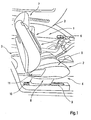
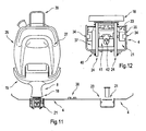
- FIG. 1 shows the first row of seats in a passenger car. Illustrated are in the vehicle interior 1 in particular the seats 2 for the driver and front passenger and the center console 3.
- the bottom 4 of the vehicle is flat.
- the respective seat 2 has a seat cushion 5 and a backrest 6, which receives a headrest 7 in the region of its upper end.
- the seat 2 is supported and guided only by a centrally located foot 8.
- a rail not shown in this figure is embedded in the bottom 4, which thus extends in the longitudinal direction of the vehicle.
- the recess formed in the bottom 4 in the region of the rail is covered by means of a front roller blind 9 and a rear roller blind 10.
- the seat 2 controls 11 for adjusting the seat 2 and the position of the backrest 6 and the seat cushion 5 to each other.
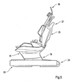
- the seat 2 has a seat cushion frame 12 and a seat back frame 13. These frames are essentially designed as a tubular frame.
- the seat back frame 13 is hinged to the seat cushion frame 12 and the seat back frame 13 is pivotable relative to the seat cushion frame 12. As a result, the backrest 6 is rotatable / inclinable to the seat cushion. 5
- the foot 8 of the seat 2 is on the one hand connected to the seat cushion frame 12 and on the other hand movable in the arranged below the bottom 4 of the vehicle rail 14.
- the foot 8 and also the lower region of the seat cushion 5 are surrounded by a carbon cladding 15, which is funnel-shaped in cross-section.
- a carbon cladding 15 which is funnel-shaped in cross-section.
- a plurality of flanges 16 are provided for attachment to the tubular frame portion 17 of the seat cushion frame 12 in the region of the seat cushion 5 facing peripheral edge.
- the carbon cladding 15 is used for additional stiffening of the seat cushion frame 12.
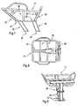
- the trained as shell carbon trim 15 and the aperture 18 are connected to each other via a stepped flange 19 by gluing or a press fit.
- a peripheral flange 20 forwards and on the sides is formed for fastening the seat cushion 5 (seat cushion padding).
- this Z-shaped so that a piping of the seat cushion 5 during assembly can engage behind an inwardly directed edge of the flange ( FIG. 6 ).
- the bottom 4 is U-shaped embossed in the longitudinal direction, so that there is a recess 21.
- an adjusting mechanism for the seat 2 is housed in the embossment / recess 21, an adjusting mechanism for the seat 2 is housed.
- the slot-shaped upper opening 23 of the recess 21 is covered on both sides of the foot by the front roller 9 and the rear roller 10. These roller blinds are guided in guide rails 24 arcuately (180 °).
- the backrest is electrically adjusted in its inclination by means of a belt drive, not shown.
- a belt drive not shown.
- protective covers are formed to cover the belt drive.
- a carbon trim 25 on the tubular frame portion 26 of the backrest frame 13 is attached by means of flange mounting.
- a handle 27 is integrated with rear passengers.
- Reference numeral 39 denotes a headrest mount.
- the carbon panels 15 and 25 contribute to increasing stiffness and reducing weight.
- the seat cushion frame 12 is adapted to receive the seat cushion 5 (seat cushion pad). It has the tube frame portion 17, which is formed as a circumferential tube, are attached to the cross braces 28 and braces 22 by welding. In the lower part of the struts 22 and 28 are connected to an approximately ground-parallel terminal plate 29, are attached to the two simultaneously substantially parallel support posts 30 of the seat 2 releasably secured. These support posts 30 form the foot 8.
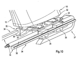
- the support posts 30 have for attachment of the seat 2 on a connection plate 31 which corresponds in contour to the connection plate 29 of the cross braces 28 and is connected thereto by screws ( FIGS. 7 to 9 ).
- the Support posts 30 have a connecting flange 32 which is connected to the carriage 33 of the guide rail 14 for supporting the seat 2.
- the guide rail 14 has two parallel rail sections 34 which guide the carriage 33 ( FIG. 10 ).
- the structure between the foot 8 and the guide rail 14 is as follows:
- the connecting flange 32 is connected by screws to the carriage 33.
- the guide rail 14 sliding shoes 35 are attached on both sides. This encompasses the rail portions 34 of the guide rail 14.
- an electrically operated spindle drive 36 By means of an electrically operated spindle drive 36, the seat 2 is adjusted in the longitudinal direction.
- a cable channel 37 is still provided for the electrical connections and controls of the seat 2.
- the two mutually parallel recesses 21 are provided for receiving the driver's seat and passenger seat and the seats located behind, also a rail 38 is arranged for slidably receiving the center console 3 between them.
- the reference numeral 40 the attachment of the guide rail 14 at the bottom 4 by the reference numeral 41 denotes the bearing for the spindle 42 of the spindle drive 36 ( FIG. 12 ).
- the guide rails 24 for the blinds 9 and 10 are on the one hand under the bottom 4 connected to the bottom 4 and the upper region, thus the opening 23 via a spacer 43 connected to each other.
- the guide rail 14 is connected to the bottom 4 in the region of the recess 21, for example by screws or rivets.
Landscapes
- Engineering & Computer Science (AREA)
- Aviation & Aerospace Engineering (AREA)
- Transportation (AREA)
- Mechanical Engineering (AREA)
- Seats For Vehicles (AREA)
Claims (24)
- Véhicule automobile comportant un siège (2), en particulier un véhicule léger comportant un siège avant, étant donné que le siège (2) est monté sur un rail (14) et présente un cadre de coussin de siège (12) pour l'accueil d'un coussin de siège (5), et un cadre de dossier de siège (13) pour l'accueil d'un dossier (6), et que le cadre de dossier de siège (13) repose dans le cadre de coussin de siège (12), et que le siège (2) présente un pied (8) qui est formé par au moins un support d'appui (30) et est attaché d'une part avec le cadre de coussin de siège (12) et d'autre part, il repose sur le rail (14) qui se trouve au dessous du fond (4) de l'intérieur (1) du véhicule automobile, et que le support du siège (2) ne s'effectue qu'au moyen du pied (8), caractérisé en ce que une enfonçure (21) incorpore le rail (14), en ce que le pied est muni d'un habillage (15) et que des moyens (9,10) sont prévus pour couvrir l'enfonçure (21) au niveau de la zone qui n'est pas occupée par le pied (8).
- Véhicule automobile selon revendication 1, caractérisé en ce que le cadre de coussin de siège (12) présente des sections tubulaires (17).
- Véhicule automobile selon revendication 1 ou 2, caractérisé en ce que le cadre de dossier de siège (13) présente des sections tubulaires (26).
- Véhicule automobile selon l'une des revendications 1 à 3, caractérisé en ce que le cadre de coussin de siège (12) est monté au centre du pied (8).
- Véhicule automobile selon l'une des revendications 1 à 4, caractérisé en ce que le pied (8) est constitué de deux supports d'appui (30) qui sont disposés pour l'essentiel parallèle l'un à l'autre.
- Véhicule automobile selon l'une des revendications 1 à 5, caractérisé en ce que le pied (8) et la zone inferieur du coussin de siège (5) sont munis d'un habillage (15) commun.
- Véhicule automobile selon l'une des revendications 1 à 6, caractérisé en ce que l'habillage (15) est fixé au cadre de coussin de siège (12).
- Véhicule automobile selon l'une des revendications 1 à 7, caractérisé en ce que l'habillage (15) est constituée en carbone.
- Véhicule automobile selon l'une des revendications 1 à 8, caractérisé en ce que l'habillage (15) présente dans la zone supérieure, un bride (18) rotatif en certaines parties pour la fixation du coussin de siège (5).
- Véhicule automobile selon l'une des revendications 1 à 9, caractérisé en ce que un habillage (25) est fixé à la face arrière du dossier (6), en particulier un habillage (25) constitué en carbone.
- Véhicule automobile selon revendication 10, caractérisé en ce que l'habillage (25) est fixé au cadre de dossier de siège (13).
- Véhicule automobile selon revendication 10 ou 11, caractérisé en ce que une poignée (27), pour le passager de véhicule prenant place derrière le siège (2), est intégrée dans l'habillage (25) du dossier (6).
- Véhicule automobile selon l'une des revendications 1 à 12, caractérisé en ce que le fond (4) de l'intérieur du véhicule (1) est réalisé approfondi, en forme de U, en particulier estampé en forme de U, étant donné que le rail (14) et un mécanisme de réglage (22) pour le siège (2) logent au sein de l'enfonçure (21).
- Véhicule automobile selon l'une des revendications 1 à 13, caractérisé en ce que les moyens (9, 10) sont mobiles.
- Véhicule automobile selon revendication 14, caractérisé en ce que les moyens (9, 10), pour recouvrir l'enfonçure (21), sont réalisés sous forme de volets roulants (9, 10) qui, dans le sens de coulissement du siège (2), sont disposés devant et derrière ce dernier.
- Véhicule automobile selon revendication 14 ou 15, caractérisé en ce que les moyens (9, 10), pour recouvrir l'enfonçure (21), sont logés dans des bars (24) qui sont disposés dans l'enfonçure (21).
- Véhicule automobile selon l'une des revendications 1 à 16, caractérisé en ce que un organe d'entraînement électrique destiné pour un réglage de l'inclinaison du dossier (6) est prévu.
- Véhicule automobile selon l'une des revendications 1 à 17, caractérisé en ce que le cadre de coussin de siège présente une section de cadre tubulaire (17) réalisée sous forme d'un tube rotatif, pour l'accueil du coussin de siège (5), des contre-fiches (22, 28) disposées au niveau du tube et une plaque de connexion (29) parallèle au fond qui incorpore ces dernières.
- Véhicule automobile selon revendication 18, caractérisé en ce que au moins l'un des support d'appui (30) est fixé de manière détachable à la plaque de connexion (29).
- Véhicule automobile selon l'une des revendications 1 à 19, caractérisé en ce que au moins l'un des support d'appui (30) est fixé à un chariot (33) du rail de guidage (14), en particulier fixé de manière détachable.
- Véhicule automobile selon l'une des revendications 1 à 20, caractérisé en ce que le siège (2) est capable d'être déplacé au moyen d'un entrainement à broche (36) électrique.
- Véhicule automobile selon l'une des revendications 1 à 21, caractérisé en ce que le siège (2) est monté sur le rail (14) de manière à pouvoir être déplacé.
- Véhicule automobile selon l'une des revendications 1 à 22, caractérisé en ce que le cadre de dossier de siège (13) est logé de manière pivotante, au sein du cadre de coussin de siège (12).
- Véhicule automobile selon l'une des revendications 1 à 23, caractérisé en ce que le pied (8) est formé de deux supports d'appui (30), qui sont rangés l'un après l'autre, par rapport au sens de déplacement du siège.
Priority Applications (1)
| Application Number | Priority Date | Filing Date | Title |
|---|---|---|---|
| EP08005092A EP1939031B1 (fr) | 2005-09-12 | 2006-08-16 | Véhicule automobile avec un siège |
Applications Claiming Priority (1)
| Application Number | Priority Date | Filing Date | Title |
|---|---|---|---|
| DE102005043552A DE102005043552A1 (de) | 2005-09-12 | 2005-09-12 | Kraftfahrzeug mit einem Sitz |
Related Child Applications (1)
| Application Number | Title | Priority Date | Filing Date |
|---|---|---|---|
| EP08005092A Division EP1939031B1 (fr) | 2005-09-12 | 2006-08-16 | Véhicule automobile avec un siège |
Publications (3)
| Publication Number | Publication Date |
|---|---|
| EP1762423A2 EP1762423A2 (fr) | 2007-03-14 |
| EP1762423A3 EP1762423A3 (fr) | 2007-10-17 |
| EP1762423B1 true EP1762423B1 (fr) | 2008-10-29 |
Family
ID=37546738
Family Applications (2)
| Application Number | Title | Priority Date | Filing Date |
|---|---|---|---|
| EP06016990A Not-in-force EP1762423B1 (fr) | 2005-09-12 | 2006-08-16 | Véhicule automobile avec un siège |
| EP08005092A Not-in-force EP1939031B1 (fr) | 2005-09-12 | 2006-08-16 | Véhicule automobile avec un siège |
Family Applications After (1)
| Application Number | Title | Priority Date | Filing Date |
|---|---|---|---|
| EP08005092A Not-in-force EP1939031B1 (fr) | 2005-09-12 | 2006-08-16 | Véhicule automobile avec un siège |
Country Status (3)
| Country | Link |
|---|---|
| EP (2) | EP1762423B1 (fr) |
| AT (1) | ATE446213T1 (fr) |
| DE (3) | DE102005043552A1 (fr) |
Families Citing this family (5)
| Publication number | Priority date | Publication date | Assignee | Title |
|---|---|---|---|---|
| DE102009056414A1 (de) * | 2009-12-01 | 2011-06-09 | GM Global Technology Operations LLC, ( n. d. Ges. d. Staates Delaware ), Detroit | Schienenanordnung für einen Kraftfahrzeugsitz |
| DE102009059837A1 (de) * | 2009-12-21 | 2011-06-22 | GM Global Technology Operations LLC, ( n. d. Ges. d. Staates Delaware ), Mich. | Fahrzeugsitz |
| DE102010021509A1 (de) | 2010-05-26 | 2011-12-01 | Gm Global Technology Operations Llc (N.D.Ges.D. Staates Delaware) | Fahrzeuginterieurbezug |
| US9669734B2 (en) | 2015-08-27 | 2017-06-06 | Tesla, Inc. | Monopost for free-standing vehicle seat |
| CN113677558A (zh) * | 2019-03-29 | 2021-11-19 | 提爱思科技股份有限公司 | 车辆座椅 |
Family Cites Families (10)
| Publication number | Priority date | Publication date | Assignee | Title |
|---|---|---|---|---|
| US5368355A (en) * | 1993-10-04 | 1994-11-29 | General Motors Corporation | Vehicle seat having normal usage and storage positions |
| DE29518937U1 (de) * | 1995-11-29 | 1996-01-18 | Schneider Fahrkomfort GmbH, 68167 Mannheim | Fahrzeugsitz mit integriertem 3-Punkt-Sicherheitsgurt |
| DE19746648C2 (de) * | 1996-10-19 | 2001-12-06 | Faurecia Autositze Gmbh & Co | Kraftfahrzeugsitz |
| US6213557B1 (en) * | 1998-05-12 | 2001-04-10 | Johnson Controls Technology Company | Vehicle seat assembly with thermoformed fibrous suspension panel |
| DE19912182A1 (de) * | 1999-03-18 | 2000-09-21 | Volkswagen Ag | Fahrzeugsitz |
| NL1012287C2 (nl) | 1999-06-10 | 2000-12-12 | Style Automotive B V B | Systeem voor het losneembaar bevestigen van een stoel aan een ondergrond alsmede frame geschikt voor een dergelijk systeem. |
| AU728411B3 (en) * | 2000-01-04 | 2001-01-11 | G & J Lewis Enterprises Pty Ltd | Suspension seat |
| FR2812251B1 (fr) * | 2000-07-27 | 2003-01-03 | Antolin Grupo Ing Sa | Dispositif de guidage et d'ancrage pour siege amovible de vehicule |
| FR2828451B1 (fr) * | 2001-08-10 | 2003-12-12 | Productions Sa B V | Systeme pour la fixation d'au moins un siege sur un plancher de vehicule, et plancher de vehicule equipe d'un tel systeme de fixation |
| DE10144065B4 (de) * | 2001-09-07 | 2004-02-12 | Isringhausen Gmbh & Co. Kg | Anordnung zur Befestigung eines Funktionselementes in einem Fahrzeug |
-
2005
- 2005-09-12 DE DE102005043552A patent/DE102005043552A1/de not_active Withdrawn
-
2006
- 2006-08-16 AT AT08005092T patent/ATE446213T1/de active
- 2006-08-16 DE DE502006001926T patent/DE502006001926D1/de active Active
- 2006-08-16 EP EP06016990A patent/EP1762423B1/fr not_active Not-in-force
- 2006-08-16 EP EP08005092A patent/EP1939031B1/fr not_active Not-in-force
- 2006-08-16 DE DE502006005212T patent/DE502006005212D1/de active Active
Also Published As
| Publication number | Publication date |
|---|---|
| EP1939031B1 (fr) | 2009-10-21 |
| DE502006001926D1 (de) | 2008-12-11 |
| ATE446213T1 (de) | 2009-11-15 |
| EP1762423A3 (fr) | 2007-10-17 |
| EP1939031A1 (fr) | 2008-07-02 |
| EP1762423A2 (fr) | 2007-03-14 |
| DE502006005212D1 (de) | 2009-12-03 |
| DE102005043552A1 (de) | 2007-03-15 |
Similar Documents
| Publication | Publication Date | Title |
|---|---|---|
| DE102005050384B4 (de) | Liegerücksitzsystem | |
| DE10219764B4 (de) | Klappbare Fahrzeugbordwand mit daran befestigten Sitzkomponenten | |
| EP0407741B1 (fr) | Appui-tête pour sièges arrières | |
| EP1636062B1 (fr) | Siege de sport destine a un vehicule, notamment a un vehicule motorise | |
| DE10209185C1 (de) | Fahrzeugsitz mit einstellbarer Beinabstützung | |
| EP1630031A2 (fr) | Siège de véhicule | |
| WO2014124630A1 (fr) | Siège de véhicule, notamment de véhicule automobile | |
| DE102008008924A1 (de) | Verstellbarer Sitz | |
| DE69811672T2 (de) | Einziehbare kopfstütze für kraftwagen | |
| DE102020125494A1 (de) | Fahrzeugsitz mit einer Fuß- und/oder Wadenstütze | |
| DE102008064523B4 (de) | Verriegelungs-/Verstellanordnung und damit ausgestatteter Personenkraftwagen | |
| DE10039789C2 (de) | Kraftfahrzeug, insbesondere Personenkraftwagen | |
| DE3022617A1 (de) | Sitzanordnung fuer kraftfahrzeuge | |
| DE10392188T5 (de) | Fahrzeugsitz | |
| EP1762423B1 (fr) | Véhicule automobile avec un siège | |
| DE10258165B4 (de) | Herausnehmbarer Fahrzeugsitz | |
| DE102019123684A1 (de) | Komfortmodul für einen Fahrzeugsitz | |
| DE10334551B3 (de) | Kopfstütze für die Rückenlehne von Automobilsitzen, insbesondere von Rücksitzen | |
| DE102019125035B4 (de) | Fahrzeugsitz mit verstellbarer Armlehne | |
| DE102011109630A1 (de) | Sitzanlage, insbesondere Fahrzeugsitz, für einen Kraftwagen | |
| DE102009039470A1 (de) | Fußstütze für einen Insassen eines Kraftfahrzeuges | |
| DE102009012811A1 (de) | Liege für ein Kraftfahrzeug | |
| DE102018215733A1 (de) | Sitzbank eines Fahrzeugs und Fahrzeug | |
| DE10336307A1 (de) | Sitz- und/oder Liegeeinrichtung für einen Fahr zeuginnenraum | |
| EP3597161B1 (fr) | Dispositif de fixation destiné à fixer un fauteuil roulant |
Legal Events
| Date | Code | Title | Description |
|---|---|---|---|
| PUAI | Public reference made under article 153(3) epc to a published international application that has entered the european phase |
Free format text: ORIGINAL CODE: 0009012 |
|
| AK | Designated contracting states |
Kind code of ref document: A2 Designated state(s): AT BE BG CH CY CZ DE DK EE ES FI FR GB GR HU IE IS IT LI LT LU LV MC NL PL PT RO SE SI SK TR |
|
| AX | Request for extension of the european patent |
Extension state: AL BA HR MK YU |
|
| PUAL | Search report despatched |
Free format text: ORIGINAL CODE: 0009013 |
|
| AK | Designated contracting states |
Kind code of ref document: A3 Designated state(s): AT BE BG CH CY CZ DE DK EE ES FI FR GB GR HU IE IS IT LI LT LU LV MC NL PL PT RO SE SI SK TR |
|
| AX | Request for extension of the european patent |
Extension state: AL BA HR MK YU |
|
| 17P | Request for examination filed |
Effective date: 20080314 |
|
| GRAP | Despatch of communication of intention to grant a patent |
Free format text: ORIGINAL CODE: EPIDOSNIGR1 |
|
| AKX | Designation fees paid |
Designated state(s): DE ES FR GB SE |
|
| GRAS | Grant fee paid |
Free format text: ORIGINAL CODE: EPIDOSNIGR3 |
|
| GRAA | (expected) grant |
Free format text: ORIGINAL CODE: 0009210 |
|
| AK | Designated contracting states |
Kind code of ref document: B1 Designated state(s): DE ES FR GB SE |
|
| REG | Reference to a national code |
Ref country code: GB Ref legal event code: FG4D Free format text: NOT ENGLISH |
|
| REF | Corresponds to: |
Ref document number: 502006001926 Country of ref document: DE Date of ref document: 20081211 Kind code of ref document: P |
|
| REG | Reference to a national code |
Ref country code: GB Ref legal event code: 732E Free format text: REGISTERED BETWEEN 20090305 AND 20090311 |
|
| PG25 | Lapsed in a contracting state [announced via postgrant information from national office to epo] |
Ref country code: ES Free format text: LAPSE BECAUSE OF FAILURE TO SUBMIT A TRANSLATION OF THE DESCRIPTION OR TO PAY THE FEE WITHIN THE PRESCRIBED TIME-LIMIT Effective date: 20090209 |
|
| PG25 | Lapsed in a contracting state [announced via postgrant information from national office to epo] |
Ref country code: SE Free format text: LAPSE BECAUSE OF FAILURE TO SUBMIT A TRANSLATION OF THE DESCRIPTION OR TO PAY THE FEE WITHIN THE PRESCRIBED TIME-LIMIT Effective date: 20090129 |
|
| PLBE | No opposition filed within time limit |
Free format text: ORIGINAL CODE: 0009261 |
|
| STAA | Information on the status of an ep patent application or granted ep patent |
Free format text: STATUS: NO OPPOSITION FILED WITHIN TIME LIMIT |
|
| 26N | No opposition filed |
Effective date: 20090730 |
|
| REG | Reference to a national code |
Ref country code: GB Ref legal event code: 732E Free format text: REGISTERED BETWEEN 20091029 AND 20091104 |
|
| REG | Reference to a national code |
Ref country code: GB Ref legal event code: 732E Free format text: REGISTERED BETWEEN 20091105 AND 20091111 |
|
| REG | Reference to a national code |
Ref country code: DE Ref legal event code: R081 Ref document number: 502006001926 Country of ref document: DE Owner name: GM GLOBAL TECHNOLOGY OPERATIONS LLC (N. D. GES, US Free format text: FORMER OWNER: GM GLOBAL TECHNOLOGY OPERATIONS, INC., DETROIT, MICH., US Effective date: 20110323 |
|
| PGFP | Annual fee paid to national office [announced via postgrant information from national office to epo] |
Ref country code: GB Payment date: 20120815 Year of fee payment: 7 |
|
| PGFP | Annual fee paid to national office [announced via postgrant information from national office to epo] |
Ref country code: FR Payment date: 20120823 Year of fee payment: 7 |
|
| GBPC | Gb: european patent ceased through non-payment of renewal fee |
Effective date: 20130816 |
|
| REG | Reference to a national code |
Ref country code: FR Ref legal event code: ST Effective date: 20140430 |
|
| PG25 | Lapsed in a contracting state [announced via postgrant information from national office to epo] |
Ref country code: GB Free format text: LAPSE BECAUSE OF NON-PAYMENT OF DUE FEES Effective date: 20130816 |
|
| PG25 | Lapsed in a contracting state [announced via postgrant information from national office to epo] |
Ref country code: FR Free format text: LAPSE BECAUSE OF NON-PAYMENT OF DUE FEES Effective date: 20130902 |
|
| PGFP | Annual fee paid to national office [announced via postgrant information from national office to epo] |
Ref country code: DE Payment date: 20140813 Year of fee payment: 9 |
|
| REG | Reference to a national code |
Ref country code: DE Ref legal event code: R119 Ref document number: 502006001926 Country of ref document: DE |
|
| PG25 | Lapsed in a contracting state [announced via postgrant information from national office to epo] |
Ref country code: DE Free format text: LAPSE BECAUSE OF NON-PAYMENT OF DUE FEES Effective date: 20160301 |