EP1762476B1 - Dispositif d'airbag et motocyclette comportant ledit dispositif - Google Patents
Dispositif d'airbag et motocyclette comportant ledit dispositif Download PDFInfo
- Publication number
- EP1762476B1 EP1762476B1 EP06017560A EP06017560A EP1762476B1 EP 1762476 B1 EP1762476 B1 EP 1762476B1 EP 06017560 A EP06017560 A EP 06017560A EP 06017560 A EP06017560 A EP 06017560A EP 1762476 B1 EP1762476 B1 EP 1762476B1
- Authority
- EP
- European Patent Office
- Prior art keywords
- airbag
- housing
- retainer
- tether
- motorcycle
- Prior art date
- Legal status (The legal status is an assumption and is not a legal conclusion. Google has not performed a legal analysis and makes no representation as to the accuracy of the status listed.)
- Not-in-force
Links
- 238000009499 grossing Methods 0.000 claims description 23
- 230000000452 restraining effect Effects 0.000 claims description 13
- 239000002184 metal Substances 0.000 claims description 4
- XLYOFNOQVPJJNP-UHFFFAOYSA-N water Substances O XLYOFNOQVPJJNP-UHFFFAOYSA-N 0.000 description 11
- 239000004744 fabric Substances 0.000 description 7
- 230000001681 protective effect Effects 0.000 description 7
- 239000011347 resin Substances 0.000 description 6
- 229920005989 resin Polymers 0.000 description 6
- 239000002828 fuel tank Substances 0.000 description 5
- 238000012423 maintenance Methods 0.000 description 5
- 238000000034 method Methods 0.000 description 5
- 239000000463 material Substances 0.000 description 4
- 230000003247 decreasing effect Effects 0.000 description 3
- 239000000835 fiber Substances 0.000 description 3
- 238000009434 installation Methods 0.000 description 3
- 238000003754 machining Methods 0.000 description 3
- 235000001674 Agaricus brunnescens Nutrition 0.000 description 2
- 230000004913 activation Effects 0.000 description 2
- 238000005452 bending Methods 0.000 description 2
- 239000007788 liquid Substances 0.000 description 2
- 238000012986 modification Methods 0.000 description 2
- 230000004048 modification Effects 0.000 description 2
- 238000000465 moulding Methods 0.000 description 2
- 239000002390 adhesive tape Substances 0.000 description 1
- 238000004140 cleaning Methods 0.000 description 1
- 239000011248 coating agent Substances 0.000 description 1
- 238000000576 coating method Methods 0.000 description 1
- 230000007423 decrease Effects 0.000 description 1
- 230000001419 dependent effect Effects 0.000 description 1
- 238000001514 detection method Methods 0.000 description 1
- 238000010586 diagram Methods 0.000 description 1
- 239000007769 metal material Substances 0.000 description 1
- 238000003825 pressing Methods 0.000 description 1
- 238000004080 punching Methods 0.000 description 1
- 230000000630 rising effect Effects 0.000 description 1
Images







Classifications
-
- B—PERFORMING OPERATIONS; TRANSPORTING
- B60—VEHICLES IN GENERAL
- B60R—VEHICLES, VEHICLE FITTINGS, OR VEHICLE PARTS, NOT OTHERWISE PROVIDED FOR
- B60R21/00—Arrangements or fittings on vehicles for protecting or preventing injuries to occupants or pedestrians in case of accidents or other traffic risks
- B60R21/02—Occupant safety arrangements or fittings, e.g. crash pads
- B60R21/16—Inflatable occupant restraints or confinements designed to inflate upon impact or impending impact, e.g. air bags
- B60R21/23—Inflatable members
- B60R21/231—Inflatable members characterised by their shape, construction or spatial configuration
- B60R21/2334—Expansion control features
- B60R21/2338—Tethers
-
- B—PERFORMING OPERATIONS; TRANSPORTING
- B62—LAND VEHICLES FOR TRAVELLING OTHERWISE THAN ON RAILS
- B62J—CYCLE SADDLES OR SEATS; AUXILIARY DEVICES OR ACCESSORIES SPECIALLY ADAPTED TO CYCLES AND NOT OTHERWISE PROVIDED FOR, e.g. ARTICLE CARRIERS OR CYCLE PROTECTORS
- B62J27/00—Safety equipment
- B62J27/20—Airbags specially adapted for motorcycles or the like
-
- B—PERFORMING OPERATIONS; TRANSPORTING
- B60—VEHICLES IN GENERAL
- B60R—VEHICLES, VEHICLE FITTINGS, OR VEHICLE PARTS, NOT OTHERWISE PROVIDED FOR
- B60R21/00—Arrangements or fittings on vehicles for protecting or preventing injuries to occupants or pedestrians in case of accidents or other traffic risks
- B60R2021/0002—Type of accident
- B60R2021/0004—Frontal collision
-
- B—PERFORMING OPERATIONS; TRANSPORTING
- B60—VEHICLES IN GENERAL
- B60R—VEHICLES, VEHICLE FITTINGS, OR VEHICLE PARTS, NOT OTHERWISE PROVIDED FOR
- B60R21/00—Arrangements or fittings on vehicles for protecting or preventing injuries to occupants or pedestrians in case of accidents or other traffic risks
- B60R2021/0065—Type of vehicles
- B60R2021/0088—Cycles, e.g. motorcycles
-
- B—PERFORMING OPERATIONS; TRANSPORTING
- B60—VEHICLES IN GENERAL
- B60R—VEHICLES, VEHICLE FITTINGS, OR VEHICLE PARTS, NOT OTHERWISE PROVIDED FOR
- B60R21/00—Arrangements or fittings on vehicles for protecting or preventing injuries to occupants or pedestrians in case of accidents or other traffic risks
- B60R21/02—Occupant safety arrangements or fittings, e.g. crash pads
- B60R21/16—Inflatable occupant restraints or confinements designed to inflate upon impact or impending impact, e.g. air bags
- B60R21/20—Arrangements for storing inflatable members in their non-use or deflated condition; Arrangement or mounting of air bag modules or components
- B60R21/215—Arrangements for storing inflatable members in their non-use or deflated condition; Arrangement or mounting of air bag modules or components characterised by the covers for the inflatable member
- B60R2021/21506—Arrangements for storing inflatable members in their non-use or deflated condition; Arrangement or mounting of air bag modules or components characterised by the covers for the inflatable member comprising tearing tabs, legs or the like for holding the lid before deployment
-
- B—PERFORMING OPERATIONS; TRANSPORTING
- B60—VEHICLES IN GENERAL
- B60R—VEHICLES, VEHICLE FITTINGS, OR VEHICLE PARTS, NOT OTHERWISE PROVIDED FOR
- B60R21/00—Arrangements or fittings on vehicles for protecting or preventing injuries to occupants or pedestrians in case of accidents or other traffic risks
- B60R21/02—Occupant safety arrangements or fittings, e.g. crash pads
- B60R21/16—Inflatable occupant restraints or confinements designed to inflate upon impact or impending impact, e.g. air bags
- B60R21/23—Inflatable members
- B60R21/231—Inflatable members characterised by their shape, construction or spatial configuration
- B60R21/2334—Expansion control features
- B60R21/2338—Tethers
- B60R2021/23386—External tether means
Definitions
- the present invention relates to an airbag apparatus to be mounted to a motorcycle.
- known techniques includes a technique of restraining an occupant with an airbag inflated by inflation gas in a frontal collision (e.g., refer to Japanese Unexamined Patent Application Publication No. 2003-327182 ).
- the airbag apparatus disclosed in Japanese Unexamined Patent Application Publication No. 2003-327182 has a structure in which a prefolded airbag is housed in a housing and the airbag is connected to the vehicle body (body frame) with a tether.
- the tether extends from the interior of the housing to the exterior.
- the tether may be worn out locally due to contact with a metallic member of the housing.
- the present invention has been made in view of the problem. Accordingly, it is an object of the invention to provide an improved airbag apparatus, in particular a technique effective in protecting the tether that joins the airbag to the vehicle in an airbag apparatus mounted to a motorcycle.
- a motorcycle a typical example of vehicles, includes various saddle-type vehicles that an occupant straddles, such as touring motorcycles having a fuel tank in front of an occupant seat and motor scooters having a space between an occupant seat and a handlebar-supporting head pipe.
- an airbag apparatus to be mounted to a motorcycle includes at least gas generation means, an airbag, a housing, a tether, and smoothing means.
- the gas generation means is a means for generating airbag inflation gas.
- the airbag restrains an occupant by deploying into an occupant restraining region in front of the occupant by the airbag inflation gas generated by the gas generation means in a frontal collision of the motorcycle.
- the "frontal collision” indicates that the motorcycle collides with a running or still front object such as a vehicle, a pedestrian, an obstacle or the like.
- the "occupant restraining region” is defined as a space extending in the direction of the forward movement of an occupant who is moving ahead of the motorcycle by a kinetic energy during a frontal collision, for restraining the occupant who is flung ahead of the motorcycle by the kinetic energy.
- the housing houses an airbag.
- the housing includes typically a bottomed-box-shaped retainer.
- the housing is constructed of the retainer and a cover (module cover) that covers an airbag opening at the top of the retainer.
- the tether is an elongated member extending between the interior and the exterior of the housing so as to tether the airbag in the housing to the vehicle body.
- an elongated member having a strength sufficient to retain the airbag to the vehicle body can be used.
- the "elongated member” broadly includes a belt and a strap, typically a belt-like tether made of resin fibers or the like. This tether has the function of restricting the forward movement of the airbag by retaining the airbag to the vehicle body by the tension upon completion of deployment of the airbag.
- the number of the tethers of the invention may be varied to one or more, as necessary.
- the tether with the above structure extends from the interior of the housing to the exterior.
- the airbag apparatus of the invention includes smoothing means.
- the smoothing means smoothes the sliding between the tether and a metallic contact of the housing in contact with the tether.
- the "metallic contact of the housing” may be disposed at the housing itself.
- the use of the smoothing means can reduce the sliding resistance (frictional resistance) between the metallic hard contact and the tether to enable smooth sliding, thereby preventing the wear of the tether.
- the smoothing means may adopt a structure in which a contact having a large surface area is used, or a structure in which the contact is subjected to surface grinding, thereby decreasing the sliding resistance (frictional resistance) to the tether.
- this arrangement of the airbag apparatus can improve the protection of the tether for connecting the airbag to the vehicle body.
- the smoothing means is an arcuate contact formed of a folded metal portion of the housing. That is, the metallic folded portion of the housing serves as the contact with the tether and the arcuate surface for smoothing the sliding of the tether.
- the arcuate surface is made smooth to enable the movement of the tether while maintaining surface contact with the tether in the tether moving direction when the tether moves relative to the housing with the vibration of the vehicle, the withdrawal of the tether for maintenance, or airbag deploying motion. At that time, the curvatures of the tether and the arcuate surface are substantially equal at the contact between the tether and the arcuate surface.
- the arcuate surface serves as means for guiding the tether relative to the housing while maintaining the surface contact so as to ensure that the curvature of the tether agrees with that of the arcuate surface.
- the "arcuate surface” broadly includes arcuate surfaces of various curvatures which correspond to a part of a circle or an ellipse.
- smoothing means can be made by folding the housing itself. This can simplify the structure of the smoothing means and reduce the number of components of the smoothing means.
- a motorcycle with an airbag apparatus is provided.
- the motorcycle with an airbag apparatus is a motorcycle having the airbag apparatus according to any one aspect or embodiment of the invention.
- a motorcycle mounted with an airbag apparatus in which protection of the tether for connecting the airbag to the vehicle body is improved.
- protection of the tether can be improved by using an elongated tether extending between the interior and exterior of the housing so as to tether the airbag in the housing to the vehicle body; and smoothing means that smoothes the sliding between the tether and a metallic contact of the housing in contact with the tether.
- Fig. 1 is a side view of the motorcycle 100 according to an embodiment of the invention, showing a state in which an airbag apparatus 120 is mounted to the motorcycle 100.
- Fig. 2 shows the motorcycle 100 of Fig. 1 , viewed from the top of the vehicle.
- the motorcycle 100 of the embodiment is an example of "a motorcycle” or "a motorcycle vehicle” of the invention.
- the motorcycle 100 is what is called a touring motorcycle and mainly comprises a body frame 101 including an engine and a main frame; a seat 103 that occupants can straddle; handlebars 104; a front wheel 111; and a rear wheel 112.
- a region above the body frame 101 of the motorcycle 100 and in front of an occupant seated in the seat 103 is defined as an occupant restraining region 150 in the event of a frontal collision of the motorcycle 100.
- the "frontal collision” in the embodiment indicates that the motorcycle 100 collides with various front objects (e.g., a vehicle, a pedestrian, an obstacle, and a guardrail, not shown for convenience sake).
- the "occupant restraining region 150" of the embodiment corresponds to "an occupant restraining region” of the invention, which is defined as a space extending in the direction of the forward movement of an occupant seated in the seat 103 during a frontal collision, for restraining the occupant who is flung ahead of the motorcycle by a kinetic energy.
- a front portion 102 of the body frame 101 includes a headlight, various meters, switches, a windshield, and the like.
- a fuel tank 106 is disposed at the front of a body component 105 between the front portion 102 and the seat 103.
- the airbag apparatus (also referred to as an airbag module) 120 is disposed in front of the fuel tank 106.
- Webbing covers 107 for covering a pair of right and left webbings 140 that is a component of the airbag apparatus 120 are disposed on both sides of the fuel tank 106.
- the webbings 140 cannot or can hardly be seen from the exterior owing to the covering by the webbing covers 107 in a normal state in which the airbag apparatus 120 is inoperative.
- the webbings 140 will be specifically described later in the description of the airbag apparatus 120.
- the structure of the airbag apparatus 120 of this embodiment will be specifically described with reference to Figs. 3 to 14 .
- the airbag apparatus 120 is disposed so as to face the occupant restraining region 150 for the occupant seated in the seat 103.
- the airbag apparatus 120 corresponds to "an airbag apparatus" of the invention.
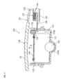
- Fig. 3 is a sectional view of the motorcycle 100 in Fig. 2 taken along line A-A;
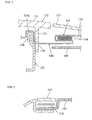
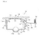
- Fig. 4 is a fragmentary enlarged view of Fig. 3 ;
- Fig. 5 is a cross sectional view of the motorcycle 100 taken along line B-B in Fig. 2 .
- the airbag apparatus 120 mainly comprises an airbag 121, an inflator 122, a retainer 123, a module cover 130, and the webbings 140.
- the airbag 121 is housed in the retainer 123 in a predetermined folded state (like a bellows or a roll).
- a predetermined folded state like a bellows or a roll.
- the direction of the inflation (deployment) of the airbag 121 is indicated by arrow 10.
- the airbag 121 is made of a material similar to airbag cloth for cars.
- the airbag 121 corresponds to "an airbag" of the invention.
- the inflator 122 is a gas supply device that generates airbag inflation gas and supplies it into the airbag 121 at a vehicle collision so that the airbag 121 in a folded state inflates while deploying from the retainer 123.
- the inflator 122 corresponds to "an inflator" of the invention.
- the retainer 123 is shaped like a bottomed box having at least an airbag housing 123a for the airbag 121 and an inflator housing (recess) 123b for the inflator 122.
- the retainer 123 houses the airbag 121 and has an opening (airbag opening) at the top, which allows the deployment of the airbag 121.
- the retainer 123 is typically formed by pressing a metallic material.
- the combination of the retainer 123 and the module cover 130 serves as "a housing that houses the airbag" in the present invention.
- the webbings 140 extend from the interior of the retainer 123 to the exterior. Accordingly, the webbings 140 may be locally worn down by contact with the retainer 123 when the vehicle vibrates during traveling, when the webbings 140 are retracted from the housing for maintenance, and when the webbings 140 are extended from a loose state with the deployment of the airbag 121.
- the retainer 123 of the embodiment therefore has a bent portion 124 at the portion with which the webbing 140 may come into contact.
- the bent portion 124 has a smooth surface (a smooth surface 124a in Fig. 4 ) at the upper end of the metal-plate retainer 123.
- the smooth surface 124a is formed by folding back (bending) the upper end (plate end) of the retainer 123.
- the smooth surface 124a is an arc-shaped smooth surface (arcuate surface) corresponding to part of a circle or ellipse and as such, it has a function of reducing the sliding resistance between the contact portion of the retainer 123 and the webbings 140 to enable smooth sliding.
- the smooth surface 124a is shaped to allow the movement of the webbings 140 while maintaining surface contact with the webbings 140 in the moving direction of the webbings 140 when the vehicle vibrates, when the webbings 140 are retracted for maintenance, and when the webbings 140 are moved with the deployment of the airbag 121.
- the curvatures of the webbings 140 and the smooth surface 124a are substantially equal at the region where the webbings 140 and the smooth surface 124a are in contact.
- the smooth surface 124a serves as means for guiding the webbings 140 relative to the retainer 123 while maintaining the surface contact so as to ensure that the curvature of the webbings 140 agrees with the curvature of the smooth surface 124a.
- This arrangement can prevent the wear of the webbings 140 made of, e.g., fibers due to contact with the metallic retainer 123 by means of the smooth surface 124a of the bent portion 124. Since, in this embodiment, the retainer 123 itself in contact with the webbings 140 has the smooth surface 124a, the smoothing structure is simplified, thus decreasing the number of components. It is preferable to increase the surface area of the smooth surface 124a of the bent portion 124 to thereby disperse the local frictional force to the webbings 140.
- the upper end of the retainer 123 corresponds to "a metallic contact of the housing" and the smooth surface 124a (the bent portion 124) of the retainer 123 corresponds to "smoothing means" and "arcuate contact” of the present invention. A more detailed description of the retainer 123 will be given hereinafter.
- the module cover 130 covers the opening (airbag opening) of the retainer 123 from above to thereby cover the airbag 121, and has at least a top plate 131 and an erect portion 132.
- the module cover 130 is typically molded of a resin material.
- the top plate 131 extends substantially horizontally in the direction of the opening surface at the airbag opening region of the retainer 123 to thereby form the upper surface of the airbag apparatus 120.
- the erect portion 132 is a plate portion and extends vertically from the lower surface (back) of the top plate 131 toward the retainer 123 to cross the extending direction of the top plate 131.
- the erect portion 132 is secured to the retainer 123 with fixing portions (fixtures 128, to be described later) of the retainer 123 to thereby join the module cover 130 and the retainer 123 together.
- a pair of right and left through holes 134 that communicate the interior of the module cover 130 with the exterior is provided at the part of the rising portion 132 adjacent to the rear of the vehicle (adjacent to the occupant).
- the webbings 140 can extend from the interior to the exterior of the module cover 130 through the through holes 134.
- the airbag 121 is tethered to the body of the motorcycle 100 with the pair of right and left elongated webbings 140.
- the webbings 140 are formed like a belt made of the same material as that of car seatbelts (resin fiber belt) or the same material as that of airbag cloth.
- the webbings 140 may be formed like a strap instead of the belt.
- a first end 141 of each webbing 140 is stitched to the airbag 121 and a second end 142 is joined to a fastener (a fastener 108 in Figs. 1 and 2 ) on the body.
- the webbings 140 extend in the front and back direction in parallel at two positions between the airbag apparatus 120 and the vehicle body. As shown in Figs.
- the webbings 140 when the airbag apparatus 120 is in an inoperative state, the webbings 140 extend in the housing space between the webbing covers 107 and the body component 105, and the upper parts of the webbings 140 are covered with the webbing covers 107.
- the webbings 140 correspond to "tethers" of the invention.
- each webbing 140 has a folded portion 143 below the webbing cover 107 so as to keep the looseness of the webbing 140 in a predetermined bunched state before the activation of the airbag apparatus 120 (while the airbag 121 is housed).
- the loose portions at the folded portions 143 of the webbings 140 are piled (folded back).
- the opposing surfaces of the loose portion are provided with a hook-and-loop fastener 144 that can temporarily hold the loose portion in the folded state (the predetermined bunched state).
- the hook-and-loop fastener 144 has a known structure, which is a detachable tape using a pile structure and is the so-called Velcro fastener. Specifically, the hook-and-loop fastener 144 has small mushroom-shaped expanded portions (or hooks) on one surface, and loops on the other surface. When the two surfaces are put together, the mushroom portions (or hooks) are caught (hooked) in the loops, so that they easily stick to each other; when they are pulled from each other, the mushrooms come out from the loops, so that they are easily peeled from each other.
- the folded (bunched) state of the folded portion 143 while the airbag is housed can temporarily be kept by the hook-and-loop fastener 144.
- the retaining force by the hook-and-loop fastener 144 is released, so that the folded (bunched) state of the folded portion 143 is released.
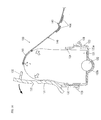
- Fig. 6 shows the structure of the folded portions 143 of the webbings 140 of the embodiment.
- the folded portions 143 are disposed substantially symmetrically. This arrangement can reduce the looseness of the webbings 140 while the airbag is housed and makes the loads of the right and left webbings 140, which extend upon the deployment of the airbag 121, on the airbag 121 substantially equal, thus being effective in deploying the airbag 121 laterally equally.
- the embodiment can employ another webbing holding means other than the hook-and-loop fastener 144, provided that the folded state of the folded portions 143 can temporarily be held.
- the folded state of the folded portions may be temporarily kept by a structure in which the folded portions are stitched up with a tear seam or a structure in which the folded portions are wound by an adhesive tape or the like.
- an appropriate structure can be adopted for temporarily holding the loose portions of the webbings 140 in a predetermined folded state (a predetermined folded-back state) or in a predetermined wound state with webbing holding means.
- Fig. 7 shows the module cover 130 and the retainer 123 of the embodiment viewed from the top of the vehicle; Fig. 8 shows them from the rear of the vehicle; Fig. 9 shows them from the side of the vehicle; Fig. 10 shows a section taken along line C-C of Fig. 7 ; and Fig. 11 shows a section taken along line D-D of Fig. 7 .
- the erect portion 132 of the module cover 130 of the embodiment has a tear line 133 along the outer periphery thereof adjacent to the rear of the vehicle (adjacent to the occupant), and two tear lines 135 along the inner periphery on both sides.
- the tear lines 133 and 135 are provided not to the top plate 131 but to the erect portion 132. Accordingly, even if a load such as an occupant or a burden is applied from above the module cover 130, the load is not directly applied to the tear lines 133 and 135, thus preventing the module cover 130 from being torn open along the tear lines 133 and 135.
- the embodiment may have a continuous tear line from the erect portion 132 of the module cover 130 across another portion of the top plate 131.
- the disposition of the through holes 134 on the tear line 133 streamlines the structure because the installation locations are shared.
- the tear lines 133 and 135 are formed by providing triangular cutouts in the erect portion 132.
- three continuous grooves with a predetermined depth, or thin portions of a substantially even thickness within the thickness of the erect portion 132 are formed in the erect portion 132 adjacent to the rear and both sides of the vehicle.
- the tear lines 133 and 135 are also referred to as "linear grooves", “thin portions”, or “fragile portions” having a linear groove of a predetermined depth.
- the module cover 130 can be smoothly torn open along the tear lines 133 and 135 of the erect portion 132 by the deploying force of the airbag 121 in the event of a vehicle accident, so that the portion of the module cover 130 above the tear lines 133 and 135 deploys toward the front of the vehicle with the portion of the erect portion 132 adjacent to the front of the vehicle as the hinge.
- the tear lines may be continuous grooves of a specified depth disposed at regular intervals, continuous perforations, or continuous slits disposed at regular intervals, instead of the continuous groove of a predetermined depth.
- the cutoffs of the tear lines 133 and 135 of the embodiment may be formed in dies during the molding of the module cover, or alternatively, may be formed by post machining such as laser beam machining or ultrasonic machining after the molding of the module cover.
- the sections of the tear lines 133 and 135 may be varied to a triangle, a semicircle, etc. as appropriate.
- the tear line 133 may be formed along the inner circumference of the erect portion 132 adjacent to the rear of the vehicle (adjacent to the occupant), while the tear lines 135 may be formed along the outer circumference of the both sides of the erect portion 132.
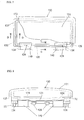
- FIG. 12 shows the retainer 123 of the embodiment viewed from the top of the vehicle;
- Fig. 13 shows a section taken along line E-E of Fig. 12 ;
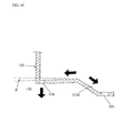
- Fig. 14 shows an enlarged view of part F in Fig. 13 .
- the retainer 123 of the embodiment has a pair of hole-like first through portions 125 at an inflator housing 123b at the bottom of the retainer 123, a pair of slit-like second through portions 126 at the right and left ends, and a pair of slit-like third through portions 127 at the front and rear ends.
- the first through portions 125, the second through portions 126, and the third through portions 127 extend vertically through the bottom of the retainer 123, and have a function of draining water entering the retainer 123 to the outside of the retainer 123.
- the water entering the retainer 123 is continuously or intermittently drained through the first through portions 125, the second through portions 126, and the third through portions 127 to the outside of the retainer 123 by gravitation.
- the housing like the retainer 123 of the embodiment is a bottomed box having an airbag opening on the top, liquid such as water or oil may be prone to enter or reside in the housing through the periphery of the airbag opening even with high tightness.
- liquid such as water or oil
- the embodiment has the first through portions 125, the second through portions 126, and the third through portions 127 for drainage at the bottom of the retainer 123.
- liquids such as oil entering the retainer 123 other than water may be drained from the retainer 123 through the first through portions 125, the second through portions 126, and the third through portions 127.
- the through portion for drainage may be holes, slits, mesh, a punching plate, or other openings.
- the installation locations and the number of installation locations of the draining through portion may be varied as appropriate.
- the first through portions 125 are located at the recessed inflator housing 123b, which is the lowest of the bottom of the retainer 123. More specifically, the bottom of the retainer 123 has a downward slope (curved slope) toward the first through portions 125. Accordingly, the water entering the retainer 123 is collected to the first through portions 125 along the slope of the inflator housing 123b, and is surely drained through the first through portions 125 to the outside of the retainer 123.
- the second through portions 126 have the function of draining the water, which enters the retainer 123 and resides at the right and left ends thereof to the outside of the retainer 123 when the motorcycle 100 is parked at an angle using a side stand, or when the vehicle body tilts laterally during driving. Furthermore, as shown in Fig. 14 , the bottom of the retainer 123 decreases in height toward the second through portions 126 (at an inclination angle ⁇ ). In other words, the bottom of the retainer 123 has a downward slope (linear slope) toward the second through portions 126.
- the water entering the retainer 123 is collected to the second through portions 126 along the slope of the bottom of the retainer 123 when the vehicle body tilts and even when the vehicle body is in a horizontal position, and is surely drained through the second through portions 126 to the outside of the retainer 123.
- the second through portions 126 are disposed at the right and left ends of the retainer 123, the second through portions 126 easily become the lowest of the bottom of the retainer 123 when the motorcycle tilts to the right or left side, thus increasing the draining function.
- the inclination angle ⁇ of the bottom of the retainer 123 may be appropriately set according to the specifications of the retainer 123.
- the third through portions 127 have the function of draining the water intruding into the retainer 123 and residing at the front and rear end.
- the motorcycle 100 tilts on an upward slope or downward slope run because the front of the body becomes higher or lower than the rear.
- the third through portion 127 on the front or rear side easily becomes the lowest of the bottom of the retainer 123, so that the water in the retainer 123 is surely drained from the retainer 123 through the third through portion 127.
- the first through portions 125 have a hole diameter of 7 mm or more (38 mm 2 or more in section area), and the second through portions 126 and the third through portions 127 have the same section area as that of the first through portions 125 or the same slit width as the hole diameter of the first through portions 125.
- FIG. 15 shows the state of the airbag 121 of the airbag apparatus 120 at the start of inflation
- Fig. 16 shows the airbag 121 at the middle of inflation
- Figs. 17 and 18 show the airbag 121 at the completion of inflation.
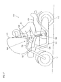
- Fig. 17 shows the airbag 121 at the completion of inflation, viewed from the side of the vehicle
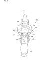
- Fig. 18 shows the airbag 121 at the completion of inflation, viewed from the top of the vehicle.
- the inflator 122 of the airbag apparatus 120 is activated to supply inflation gas generated by the inflator 122 into the airbag 121. This starts the inflation (deployment) of the airbag 121 in the direction of arrow 10 in the airbag apparatus 120 of Fig. 3 in a state before activation. Since inflation gas is continuously fed into the airbag 121, the airbag 121 is expanded in sequence from the retainer 123.
- the airbag 121 pushes the top plate 131 of the module cover 130 from below in the retainer 123 in the process of deployment.
- the module cover 130 that has received a predetermined deploying force or more from the airbag 121 is torn open along the tear lines (the tear lines 133 and 135) of the erect portion 132.
- the webbings 140 stitched to the airbag 121 are subjected to a tensile load via the first end 141.
- the webbings 140 push open the webbing covers 107 upward to thereby release the covering by the webbing covers 107.
- the module cover 130 torn open along the tear lines further receives the deploying force from the airbag 121 to deploy ahead of the vehicle with the portion of the erect portion 132 adjacent to the front of the vehicle as the hinge.
- the retaining force by the hook-and-loop fastener 144 is canceled, so that the folded state of the folded portions 143 is released.
- the loads on the airbag 121 by the webbings 140 extending during the deployment of the airbag 121 can be made substantially equal on the right and left, whereby the airbag 121 can deploy bilaterally evenly.
- the airbag 121 is completely deployed.
- the inflated airbag 121 fills the occupant restraining region 150 in front of a rider R in Fig. 17 .
- the rider R who is moving forward by the kinetic energy of the collision is restrained by the airbag 121 and the impact to the rider R during restraint is reduced.
- the webbings 140 fully extend substantially linearly between the airbag 121 and the fastener 108 to restrict the motion of the airbag 121 moving upward and forward of the vehicle by the tension thereof.
- the fully inflated airbag 121 comes into contact with the front portion 102 at the front of the vehicle, and into contact with the handlebars 104 at both sides. This arrangement stabilizes the restraint of the rider R with the fully inflated airbag 121.
- the wear of the webbings 140 due to contact with the metallic retainer 123 is prevented by the smooth surface 124a of the bent portion 124. This improves the protection of the webbings 140.
- the structure of the embodiment in which the retainer 123 itself in contact with the webbings 140 has the smooth surface 124a simplifies the structure of the smoothing means, thus reducing the number of components.
- the embodiment described above employs the smooth surface 124a (refer to Fig. 4 ) of the bent portion 124 formed by folding (bending) the upper end of the retainer 123 as smoothing means for reducing the sliding resistance between the contact of the retainer 123 and the webbings 140 to enable smooth sliding.
- the invention may use various modifications of the smoothing means.
- Figs. 19 to 21 show other implementations of the bent portion 124 of Fig. 4 or, more generally, of the smoothing means which are no embodiments of the claims.
- a coated portion 224 is disposed at the upper end of the metal plate of the retainer 123.
- the coated portion 224 is formed by coating the upper end of the retainer 123 with low-sliding-resistance resin or by bonding unwoven fabric. This coated portion 224 has the function of reducing the sliding resistance (frictional resistance) between the contact of the retainer 123 and the webbings 140 to enable smooth sliding.
- a protective cap 324 is provided at the upper end of the metal plate of the retainer 123.
- the protective cap 324 is made of low-sliding-resistance resin. This protective cap 324 has the function of reducing the sliding resistance (frictional resistance) between the contact of the retainer 123 and the webbings 140, thereby enabling smooth sliding.
- a cylindrically sewn protective fabric 424 is provided around the outer peripheries of the webbings 140 in the area corresponding to the upper end of the retainer 123.
- the protective fabric 424 is made of low-sliding-resistance resin. This protective fabric 424 has the function of reducing the sliding resistance (frictional resistance) between the contact of the retainer 123 and the webbings 140 by lying therebetween as a buffer or by wearing away by the protective fabric 424 itself, thereby enabling smooth sliding.
- the smoothing means for smoothing the sliding between the webbings and the metallic contact of the housing in contact with the webbings is disposed at the contact itself.
- the contact here may be the retainer 123 itself or a member on the retainer 123, or alternatively, may be the module cover 130 itself or a member on the module cover 130.
- the smoothing means of the invention is a structure in which an arcuate smooth contact is used and may further adopt a structure in which a contact having a large surface area is used, or a structure in which the contact is subjected to surface grinding, thereby decreasing the sliding resistance (frictional resistance) to the webbing.
- the invention may be applied to other types of motorcycle such as motor scooters having a space that enables lateral movement of the rider's legs between the handlebars and the seat and to motorcycle vehicles other than the motorcycle 100.
- the position of the airbag apparatus 120 may be varied as appropriate, provided that the airbag 121 can deploy into a desired region in a vehicle collision.
- the airbag apparatus 120 may be disposed behind or lower than that shown in Fig. 1 .
Landscapes
- Engineering & Computer Science (AREA)
- Mechanical Engineering (AREA)
- Air Bags (AREA)
Claims (3)
- Dispositif d'airbag à monter sur une motocyclette, le dispositif d'airbag comprenant :des moyens de génération de gaz (122) qui génèrent du gaz de gonflage d'airbag ;un airbag (121) qui retient un occupant en se déployant dans une région de retenue d'occupant (150) en face de l'occupant, par l'intermédiaire du gaz de gonflage d'airbag généré par les moyens de génération de gaz (122), lors d'une collision frontale de la motocyclette ;un logement (123, 130) qui loge l'airbag (121), le logement (123, 130) comprenant un dispositif de retenue (123) doté d'une paroi de logement, le logement (123, 130) comprenant un couvercle de module (130) qui recouvre l'airbag (121) dans le logement (123, 130) et qui présente une plaque supérieure (131) ;une attache allongée (140) s'étendant entre l'intérieur et l'extérieur du logement (123, 130) pour attacher l'airbag (121) dans le logement (123, 130) au corps de véhicule ; etdes moyens d'amortissement (124, 124a) qui amortissent le glissement entre l'attache (140) et un contact du logement (123, 130) en contact avec l'attache (140) ;caractérisé en ce quele contact du logement (123, 130) est un contact métallique du logement (123, 130) en contact avec l'attache (140),les moyens d'amortissement sont une surface de contact arquée (124) formée par un métal plié du logement (123), le contact arqué permettant le mouvement de l'attache (140) tout en maintenant le contact de surface avec l'attache (140) dans la direction de déplacement de l'attache (140),le couvercle de module (130) présente une partie érigée (132) s'étendant depuis la plaque supérieure (131), dans laquelle un trou débouchant (134) est prévu dans la partie érigée (132), par lequel l'attache allongée (140) s'étend d'un intérieur à un extérieur du couvercle de module (130), le trou débouchant (134) étant prévu sur une ligne de rupture (133) du couvercle de module (130), le long de laquelle le couvercle de module (130) est ouvert par rupture lorsque l'airbag (121) est déployé,une extrémité supérieure de la paroi de logement est disposée au-dessus du trou débouchant (134) dudit couvercle de module (130), etl'attache allongée (140) s'étend depuis lesdits moyens d'amortissement (124, 124a) vers ledit trou débouchant (134) entre une paroi dudit logement (123) et ladite partie érigée (132).
- Dispositif d'airbag selon la revendication 1, dans lequel la surface de contact arquée (124) est une partie pliée du dispositif de retenue (123) disposé sur une partie supérieure du dispositif de retenue (123).
- Motocyclette avec un dispositif d'airbag (120) présentant un airbag (121) qui retient un occupant en se déployant dans une région de retenue d'occupant (150) en face de l'occupant, par l'intermédiaire du gaz de gonflage d'airbag généré par des moyens de génération de gaz (122), lors d'une collision frontale de la motocyclette ; et une attache (140) allongée qui attache l'airbag (121) au corps de véhicule, dans laquelle
le dispositif d'airbag (120) est le dispositif d'airbag selon la revendication 1 ou 2.
Applications Claiming Priority (1)
| Application Number | Priority Date | Filing Date | Title |
|---|---|---|---|
| JP2005259985A JP4683388B2 (ja) | 2005-09-07 | 2005-09-07 | エアバッグ装置、エアバッグ装置付オートバイ |
Publications (3)
| Publication Number | Publication Date |
|---|---|
| EP1762476A2 EP1762476A2 (fr) | 2007-03-14 |
| EP1762476A3 EP1762476A3 (fr) | 2009-12-23 |
| EP1762476B1 true EP1762476B1 (fr) | 2012-08-15 |
Family
ID=37530080
Family Applications (1)
| Application Number | Title | Priority Date | Filing Date |
|---|---|---|---|
| EP06017560A Not-in-force EP1762476B1 (fr) | 2005-09-07 | 2006-08-23 | Dispositif d'airbag et motocyclette comportant ledit dispositif |
Country Status (4)
| Country | Link |
|---|---|
| US (1) | US7293793B2 (fr) |
| EP (1) | EP1762476B1 (fr) |
| JP (1) | JP4683388B2 (fr) |
| CN (1) | CN1927641B (fr) |
Families Citing this family (15)
| Publication number | Priority date | Publication date | Assignee | Title |
|---|---|---|---|---|
| JP4822778B2 (ja) * | 2005-09-07 | 2011-11-24 | タカタ株式会社 | エアバッグ装置、エアバッグ装置付オートバイ |
| US7789416B2 (en) * | 2005-09-08 | 2010-09-07 | Honda Motor Co., Ltd. | Air bag module cover structure |
| JP4679320B2 (ja) * | 2005-09-26 | 2011-04-27 | タカタ株式会社 | エアバッグ装置、エアバッグ装置付オートバイ |
| JP4684077B2 (ja) * | 2005-10-17 | 2011-05-18 | タカタ株式会社 | エアバッグ装置、エアバッグ装置付オートバイ |
| JP2007196787A (ja) * | 2006-01-25 | 2007-08-09 | Takata Corp | 歩行者用エアバッグ装置 |
| JP4241799B2 (ja) * | 2006-10-16 | 2009-03-18 | トヨタ自動車株式会社 | 車両用ステアリング装置 |
| JP5048571B2 (ja) * | 2008-04-02 | 2012-10-17 | タカタ株式会社 | エアバッグ装置、エアバッグ装置付オートバイ |
| KR100990035B1 (ko) * | 2008-05-09 | 2010-10-26 | 아우토리브 디벨롭먼트 아베 | 테더 홀더를 구비한 차량용 조수석 에어백 쿠션 |
| BRPI0912839A8 (pt) | 2008-05-19 | 2019-01-29 | Henkel Ag & Co Kgaa | composição de revestimento protetor contra corrosão para substratos de metal, método para proporcionar um revestimento protetor contra corrosão sobre um substrato de metal, e, substrato de matel revestido com uma composição de revestimento |
| JP4649508B2 (ja) * | 2008-09-29 | 2011-03-09 | トヨタ自動車株式会社 | 助手席用エアバッグ装置 |
| JP5479359B2 (ja) * | 2008-11-14 | 2014-04-23 | オートリブ ディベロップメント エービー | エアバッグ装置 |
| JP5400491B2 (ja) * | 2009-06-19 | 2014-01-29 | 本田技研工業株式会社 | エアバッグ装置 |
| JP6039884B2 (ja) * | 2011-03-30 | 2016-12-07 | タカタ株式会社 | エアバッグ装置 |
| CN110254575A (zh) * | 2019-05-14 | 2019-09-20 | 孙铭婧 | 一种自带安全气囊的摩托坐垫 |
| JP7775159B2 (ja) * | 2022-07-29 | 2025-11-25 | オートリブ ディベロップメント エービー | エアバッグ装置及び、その製造方法 |
Family Cites Families (12)
| Publication number | Priority date | Publication date | Assignee | Title |
|---|---|---|---|---|
| US4211432A (en) * | 1977-12-28 | 1980-07-08 | Toyota Jidosha Kogyo Kabushiki Kaisha | Webbing guide |
| US4505411A (en) * | 1983-09-16 | 1985-03-19 | Munn Laurie P | Motorcycle firearm carrier |
| US5869907A (en) * | 1996-01-23 | 1999-02-09 | Marler; Rick A. | Modular wiring harness for a vehicle |
| JP3592447B2 (ja) * | 1996-07-25 | 2004-11-24 | 本田技研工業株式会社 | 自動二輪車用エアバッグ装置 |
| US5762367A (en) * | 1997-04-10 | 1998-06-09 | General Motors Corporation | Air bag module with inflation control device |
| ES2147502B1 (es) * | 1997-12-16 | 2001-03-01 | Juan S A J | Cable intermediario aplicable a carburadores. |
| JP2001310696A (ja) * | 2000-04-28 | 2001-11-06 | Takata Corp | エアバッグおよびこのエアバッグを用いたエアバッグ装置 |
| JP4633910B2 (ja) | 2000-11-02 | 2011-02-16 | ヤマハ発動機株式会社 | 自動二輪車用エアバッグ装置 |
| JP2002137780A (ja) | 2000-11-02 | 2002-05-14 | Yamaha Motor Co Ltd | 自動二輪車用エアバッグ装置 |
| JP4310115B2 (ja) | 2002-03-06 | 2009-08-05 | 本田技研工業株式会社 | エアバッグ装置付きスクータ型自動二輪車 |
| JP4084592B2 (ja) * | 2002-04-18 | 2008-04-30 | 本田技研工業株式会社 | スクータ型車両におけるエアバッグ装置 |
| US7410398B2 (en) * | 2004-02-06 | 2008-08-12 | Brp Us Inc. | Engine mounted oil tank |
-
2005
- 2005-09-07 JP JP2005259985A patent/JP4683388B2/ja not_active Expired - Fee Related
-
2006
- 2006-08-23 EP EP06017560A patent/EP1762476B1/fr not_active Not-in-force
- 2006-09-07 CN CN2006101517805A patent/CN1927641B/zh not_active Expired - Fee Related
- 2006-09-07 US US11/470,892 patent/US7293793B2/en active Active
Also Published As
| Publication number | Publication date |
|---|---|
| JP2007069783A (ja) | 2007-03-22 |
| CN1927641A (zh) | 2007-03-14 |
| US20070052217A1 (en) | 2007-03-08 |
| JP4683388B2 (ja) | 2011-05-18 |
| US7293793B2 (en) | 2007-11-13 |
| EP1762476A2 (fr) | 2007-03-14 |
| CN1927641B (zh) | 2012-04-25 |
| EP1762476A3 (fr) | 2009-12-23 |
Similar Documents
| Publication | Publication Date | Title |
|---|---|---|
| US7293793B2 (en) | Airbag apparatus and motorcycle having the same | |
| US7588264B2 (en) | Airbag system and motorcycle with airbag system | |
| EP1813517B1 (fr) | Système d'airbag pour motocyclette et motocyclette | |
| EP1762474B1 (fr) | Dispositif d'airbag et motocyclette avec un tel dispositif | |
| EP1813519B1 (fr) | Motocyclette dotée d'un système d'airbag | |
| EP1762475B1 (fr) | Dispositif d'airbag pour motocyclette | |
| EP1762473B1 (fr) | Dispositif d'airbag et motocyclette avec un tel dispositif | |
| EP1762472B1 (fr) | Dispositif d'airbag et motocyclette avec un tel dispositif | |
| EP1775205B1 (fr) | Dispositif d'airbag et motocyclette pourvue d'un dispositif d'airbag | |
| US7547039B2 (en) | Airbag apparatus and motorcycle having the same | |
| JP2003200812A (ja) | 自動車の側突用エアバッグ装置 |
Legal Events
| Date | Code | Title | Description |
|---|---|---|---|
| PUAI | Public reference made under article 153(3) epc to a published international application that has entered the european phase |
Free format text: ORIGINAL CODE: 0009012 |
|
| AK | Designated contracting states |
Kind code of ref document: A2 Designated state(s): AT BE BG CH CY CZ DE DK EE ES FI FR GB GR HU IE IS IT LI LT LU LV MC NL PL PT RO SE SI SK TR |
|
| AX | Request for extension of the european patent |
Extension state: AL BA HR MK YU |
|
| PUAL | Search report despatched |
Free format text: ORIGINAL CODE: 0009013 |
|
| AK | Designated contracting states |
Kind code of ref document: A3 Designated state(s): AT BE BG CH CY CZ DE DK EE ES FI FR GB GR HU IE IS IT LI LT LU LV MC NL PL PT RO SE SI SK TR |
|
| AX | Request for extension of the european patent |
Extension state: AL BA HR MK RS |
|
| RIC1 | Information provided on ipc code assigned before grant |
Ipc: B60R 21/233 20060101ALI20091119BHEP Ipc: B62J 27/00 20060101AFI20061222BHEP |
|
| 17P | Request for examination filed |
Effective date: 20100212 |
|
| AKX | Designation fees paid |
Designated state(s): DE GB |
|
| 17Q | First examination report despatched |
Effective date: 20110818 |
|
| REG | Reference to a national code |
Ref country code: DE Ref legal event code: R079 Ref document number: 602006031378 Country of ref document: DE Free format text: PREVIOUS MAIN CLASS: B62J0027000000 Ipc: B60R0021233800 |
|
| GRAP | Despatch of communication of intention to grant a patent |
Free format text: ORIGINAL CODE: EPIDOSNIGR1 |
|
| RIC1 | Information provided on ipc code assigned before grant |
Ipc: B62J 27/00 20060101ALI20120209BHEP Ipc: B60R 21/2338 20110101AFI20120209BHEP |
|
| GRAS | Grant fee paid |
Free format text: ORIGINAL CODE: EPIDOSNIGR3 |
|
| GRAA | (expected) grant |
Free format text: ORIGINAL CODE: 0009210 |
|
| AK | Designated contracting states |
Kind code of ref document: B1 Designated state(s): DE GB |
|
| REG | Reference to a national code |
Ref country code: GB Ref legal event code: FG4D |
|
| REG | Reference to a national code |
Ref country code: DE Ref legal event code: R096 Ref document number: 602006031378 Country of ref document: DE Effective date: 20121011 |
|
| PLBE | No opposition filed within time limit |
Free format text: ORIGINAL CODE: 0009261 |
|
| STAA | Information on the status of an ep patent application or granted ep patent |
Free format text: STATUS: NO OPPOSITION FILED WITHIN TIME LIMIT |
|
| 26N | No opposition filed |
Effective date: 20130516 |
|
| REG | Reference to a national code |
Ref country code: DE Ref legal event code: R097 Ref document number: 602006031378 Country of ref document: DE Effective date: 20130516 |
|
| PGFP | Annual fee paid to national office [announced via postgrant information from national office to epo] |
Ref country code: DE Payment date: 20130821 Year of fee payment: 8 |
|
| PGFP | Annual fee paid to national office [announced via postgrant information from national office to epo] |
Ref country code: GB Payment date: 20130821 Year of fee payment: 8 |
|
| REG | Reference to a national code |
Ref country code: DE Ref legal event code: R119 Ref document number: 602006031378 Country of ref document: DE |
|
| GBPC | Gb: european patent ceased through non-payment of renewal fee |
Effective date: 20140823 |
|
| REG | Reference to a national code |
Ref country code: DE Ref legal event code: R119 Ref document number: 602006031378 Country of ref document: DE Effective date: 20150303 |
|
| PG25 | Lapsed in a contracting state [announced via postgrant information from national office to epo] |
Ref country code: GB Free format text: LAPSE BECAUSE OF NON-PAYMENT OF DUE FEES Effective date: 20140823 Ref country code: DE Free format text: LAPSE BECAUSE OF NON-PAYMENT OF DUE FEES Effective date: 20150303 |