EP1762532A2 - Gâche pour appareil de levage - Google Patents
Gâche pour appareil de levage Download PDFInfo
- Publication number
- EP1762532A2 EP1762532A2 EP05257594A EP05257594A EP1762532A2 EP 1762532 A2 EP1762532 A2 EP 1762532A2 EP 05257594 A EP05257594 A EP 05257594A EP 05257594 A EP05257594 A EP 05257594A EP 1762532 A2 EP1762532 A2 EP 1762532A2
- Authority
- EP
- European Patent Office
- Prior art keywords
- retaining
- shank
- keeper
- collar
- set forth
- Prior art date
- Legal status (The legal status is an assumption and is not a legal conclusion. Google has not performed a legal analysis and makes no representation as to the accuracy of the status listed.)
- Granted
Links
- 238000000034 method Methods 0.000 claims description 9
- 239000012530 fluid Substances 0.000 description 5
- 239000004519 grease Substances 0.000 description 4
- 238000007689 inspection Methods 0.000 description 3
- 230000004323 axial length Effects 0.000 description 2
- 239000000428 dust Substances 0.000 description 2
- 239000000314 lubricant Substances 0.000 description 2
- 238000012423 maintenance Methods 0.000 description 2
- 239000000463 material Substances 0.000 description 2
- 238000012986 modification Methods 0.000 description 2
- 230000004048 modification Effects 0.000 description 2
- 239000004677 Nylon Substances 0.000 description 1
- 229910000639 Spring steel Inorganic materials 0.000 description 1
- 229910000831 Steel Inorganic materials 0.000 description 1
- 230000000712 assembly Effects 0.000 description 1
- 238000000429 assembly Methods 0.000 description 1
- 238000010276 construction Methods 0.000 description 1
- 230000013011 mating Effects 0.000 description 1
- 229920001778 nylon Polymers 0.000 description 1
- 238000012856 packing Methods 0.000 description 1
- 230000000737 periodic effect Effects 0.000 description 1
- 239000003208 petroleum Substances 0.000 description 1
- 239000010959 steel Substances 0.000 description 1
Images


Classifications
-
- E—FIXED CONSTRUCTIONS
- E21—EARTH OR ROCK DRILLING; MINING
- E21B—EARTH OR ROCK DRILLING; OBTAINING OIL, GAS, WATER, SOLUBLE OR MELTABLE MATERIALS OR A SLURRY OF MINERALS FROM WELLS
- E21B19/00—Handling rods, casings, tubes or the like outside the borehole, e.g. in the derrick; Apparatus for feeding the rods or cables
- E21B19/02—Rod or cable suspensions
-
- B—PERFORMING OPERATIONS; TRANSPORTING
- B66—HOISTING; LIFTING; HAULING
- B66C—CRANES; LOAD-ENGAGING ELEMENTS OR DEVICES FOR CRANES, CAPSTANS, WINCHES, OR TACKLES
- B66C1/00—Load-engaging elements or devices attached to lifting or lowering gear of cranes or adapted for connection therewith for transmitting lifting forces to articles or groups of articles
- B66C1/10—Load-engaging elements or devices attached to lifting or lowering gear of cranes or adapted for connection therewith for transmitting lifting forces to articles or groups of articles by mechanical means
- B66C1/22—Rigid members, e.g. L-shaped members, with parts engaging the under surface of the loads; Crane hooks
- B66C1/34—Crane hooks
-
- F—MECHANICAL ENGINEERING; LIGHTING; HEATING; WEAPONS; BLASTING
- F16—ENGINEERING ELEMENTS AND UNITS; GENERAL MEASURES FOR PRODUCING AND MAINTAINING EFFECTIVE FUNCTIONING OF MACHINES OR INSTALLATIONS; THERMAL INSULATION IN GENERAL
- F16G—BELTS, CABLES, OR ROPES, PREDOMINANTLY USED FOR DRIVING PURPOSES; CHAINS; FITTINGS PREDOMINANTLY USED THEREFOR
- F16G15/00—Chain couplings, Shackles; Chain joints; Chain links; Chain bushes
- F16G15/08—Swivels
-
- F—MECHANICAL ENGINEERING; LIGHTING; HEATING; WEAPONS; BLASTING
- F16—ENGINEERING ELEMENTS AND UNITS; GENERAL MEASURES FOR PRODUCING AND MAINTAINING EFFECTIVE FUNCTIONING OF MACHINES OR INSTALLATIONS; THERMAL INSULATION IN GENERAL
- F16B—DEVICES FOR FASTENING OR SECURING CONSTRUCTIONAL ELEMENTS OR MACHINE PARTS TOGETHER, e.g. NAILS, BOLTS, CIRCLIPS, CLAMPS, CLIPS OR WEDGES; JOINTS OR JOINTING
- F16B2200/00—Constructional details of connections not covered for in other groups of this subclass
- F16B2200/69—Redundant disconnection blocking means
-
- Y—GENERAL TAGGING OF NEW TECHNOLOGICAL DEVELOPMENTS; GENERAL TAGGING OF CROSS-SECTIONAL TECHNOLOGIES SPANNING OVER SEVERAL SECTIONS OF THE IPC; TECHNICAL SUBJECTS COVERED BY FORMER USPC CROSS-REFERENCE ART COLLECTIONS [XRACs] AND DIGESTS
- Y10—TECHNICAL SUBJECTS COVERED BY FORMER USPC
- Y10T—TECHNICAL SUBJECTS COVERED BY FORMER US CLASSIFICATION
- Y10T403/00—Joints and connections
- Y10T403/32—Articulated members
- Y10T403/32114—Articulated members including static joint
- Y10T403/32213—Articulate joint is a swivel
Definitions
- the present invention relates to a retaining keeper assembly for a hoisting device.
- the present invention relates to a retaining keeper assembly for a pulley block that will accommodate rotating swivel action and be sealed from the elements while also permitting easy disassembly and reassembly.
- API American Petroleum Institute
- Recommended Practice 8B requires the periodic inspection at specific times of hoisting devices including disassembly to inspect specific components.
- the present invention is directed to a retaining keeper assembly for a hoisting device, such as a pulley block.
- the hoisting device includes a lower block case having a cylindrical recessed opening for receipt of a shank.
- a shank supporting a load carrying member terminates in an end having a plurality of parallel circumferential grooves or recesses in the shank. Each of the grooves is perpendicular to an axis of the shank.
- the shank passes through the circular cylindrical opening in the lower block case.
- a thrust bearing fits over and surrounds the shank below the level of the circumferential grooves and is supported in the cylindrical recess of the lower block case. The thrust bearing accommodates rotational or swivel movement between the lower block and the shank.
- the retaining keeper assembly includes a split retaining collar fashioned from a pair of semi-circular halves. When the halves are brought together, they form a cylindrical collar having a plurality of interior circular protrusions. The interior circular protrusions mate with the grooves in the shank. The collar rests on the thrust bearing so that the collar prevents axial movement of the shank. Load force passes from the hook to the retaining collar, through the thrust bearing and then to the case.
- a cylindrical retaining collar cover has cylindrical walls, a closed top and an open bottom.
- the cylindrical walls of the retaining collar cover have an inner diameter which closely fit the outer diameter of the retaining collar when the collar halves are brought together around the shank.
- the retaining collar cover entirely surrounds the retaining collar halves and also keeps them from separating.
- the retaining keeper assembly also includes a fastener mechanism in order to removably fasten the retaining collar cover to the collar and to the shank.
- a pair of fasteners passes through openings in the retaining collar cover and engages threaded openings in the retaining collar halves.
- a pair of fasteners pass through openings in the retaining collar cover and engages threaded openings in the end of the shank.
- a flexible circular seal has an inner diameter which mates with the exterior of the retaining collar cover and an outer diameter which mates with the cylindrical recess of the lower block case, thereby forming a fluid tight seal.
- the split retaining collar mates with the shank as described in the initial embodiment.
- a cylindrical retaining collar keeper ring has cylindrical walls, and an open top and an open bottom.
- the cylindrical walls of the retaining collar keeper ring have an inner diameter which closely fit the outer diameter of the retaining collar when the collar halves are brought together around the shank. The keeper ring, thus, keeps the collar halves from separating.
- a pair of circular retaining rings are positioned adjacent the open top and open bottom of the keeper ring and trap the keeper ring in place.
- the retaining rings are received in external retaining grooves recessed into the external surface of the retaining collar.
- a cover having cylindrical walls, an open bottom and a closed top may be placed over the assembled keeper ring, the retaining rings and the split halves of the retaining collar.
- Figure 1 is a perspective view of an initial preferred embodiment of a retaining keeper assembly 10 shown in use with a hoisting device.
- a tubing block with a hook 12 used for oilfield tubing applications is shown. It will be appreciated that other types of hooks, shackles or lifting devices might be employed within the spirit and scope of the present invention.
- the hook 12 is designed to permit rotation or swivel movement between it and a hoisting device.
- the hoisting device may take many forms, such as a pulley block having sheaves and an upper and lower case. Lower block case 14 is shown in Figure 1 with the balance of the pulley block removed for ease of viewing.
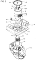
- Figure 2 illustrates an exploded view of the retaining keeper assembly 10 so that the various elements or components are visible.
- a shank 16 extends from the hook 12.
- the shank 16 terminates in an end having a plurality of parallel circumferential grooves 18 or recesses in the shank, each of the grooves being perpendicular to an axis of the shank 16.
- the shank 16 passes through a circular opening 20 in the lower block case 14.
- the lower block case includes a cylindrical recess into which is received a circular thrust bearing 24.
- the circular thrust bearing 24 fits over and surrounds the shank 16 below the level of the grooves 18.
- the thrust bearing 24 accommodates rotational or swivel movement between the lower block case 14 and the shank 16.
- the retaining keeper assembly 10 also includes a split retaining collar fashioned from a pair of semi-circular halves 26 and 28.
- the retaining collar halves 26 and 28 are brought together to form a cylindrical collar having a plurality of interior circular protrusions 30.
- the interior circular protrusions mate with the grooves 18 in the shank 16.
- a base of the retaining collar rests on and is supported by the thrust bearing. The collar, thus, prevents axial movement of said shaft.
- Grease or lubricant may be inserted between the grooves 18 and the protrusions of the collar, although the collar and shank move together once assembled.
- a cylindrical retaining collar cover 32 has cylindrical walls, a closed top and an open bottom.
- the cylindrical retaining collar cover 32 has an inner diameter slightly larger than the outer diameter of the retaining collar when the collar halves 26 and 28 are brought together around the shank 16. When assembled as shown in Figure 1, the retaining collar cover 32 entirely surrounds the retaining collar halves 26 and 28 and also keeps them from separating.
- the retaining keeper assembly 10 also includes a fastener mechanism in order to removably fasten the retaining collar cover 32 to the collar and to the shank 16.
- a pair of fasteners in the form of threaded bolts 34 pass through openings in the retaining collar cover 32 and engage threaded openings 36 in the retaining collar halves 26 and 28.
- a pair of fasteners in the form of threaded bolts 38 pass through openings in the retaining collar cover 32 and engage threaded openings 42 in the shank 16. Rotational movement of the shank, thus, causes rotational movement of the split retaining collar and the retaining collar cover.
- a flexible circular seal 40 has an inner edge which mates with the exterior cylindrical walls of the retaining collar cover 32.
- the circular seal also has an outer edge which will mate with the cylindrical recess 22 of the lower block case 14. Accordingly, when the circular seal 40 is in place, it creates a fluid tight seal between the retaining collar cover and the block case 14.
- An optional cap bolt 44 may be inserted in a center opening through the top of the retaining collar cover 32. Once the other fasteners 34 and 38 have been removed and the seal 40 removed, the cap bolt 44 may be used by rotating in a clockwise direction to force the retaining collar cover away from the top of the shank. The cap bolt, thus, will assist in disassembly of the retaining keeper assembly.
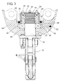
- Figure 3 illustrates a partial sectional view of the retaining keeper assembly as shown in assembled condition in Figure 1.
- a bushing 46 may be juxtaposed between the shank 16 and the lower block case 14 below the thrust bearing.
- the thrust bearing 24 resides in the cylindrical recess in the lower case.
- a circular cavity 48 is connected to a passageway 50 terminating in a grease zerk 52 so that grease may be supplied to the thrust bearing 24 as it interfaces between the block case 14 and the shank 16.
- the split retaining collar rests on and is supported on the thrust bearing. It will be observed that the collar, retaining collar cover and shank are fastened together and move together.
- the circular seal ring 40 on the outside of the cover creates a fluid tight seal.
- the thrust bearing 24 is inserted into the cylindrical recess of the lower block case 14. Thereafter, the shank 16 of the hook is inserted through the cylindrical opening in the lower block case 14 and through the thrust bearing. The circular grooves 18 will then be visible extending from the case 14.
- the split retaining collar will be installed by bringing the halves together around the shank 16 so that the interior circular protrusions of the retaining collar mate with the grooves of the shank. Thereafter, the open end of the cylindrical retaining collar cover 32 is slid over top of the split retaining collar and over top of the end of the shank 16. The retaining collar cover 32 is secured to the retaining collar with fasteners and the retaining collar cover is secured to the shank with fasteners.
- a cap bolt or other cover may be installed in the top opening to keep it in closed position.
- the circular seal 40 is brought over top of the retaining collar cover and into the recess of the block case so that a fluid tight seal is created between the exterior of the retaining collar cover and the block case.
- the foregoing procedure is performed in reverse in order to disassemble the retaining keeper assembly 10.
- the retaining keeper assembly may be easily assembled and easily disassembled for maintenance and repair.
- FIG. 4 An alternate preferred embodiment 60 of the retaining keeper assembly is shown in exploded view in Figure 4.
- the retaining keeper assembly 60 has particular application on open style blocks.
- a shank 62 extends from a hoisting device (not shown in Figure 4) as described in detail above with respect to the embodiment shown in Figures 1 through 3.
- the shank 62 terminates in an end having a plurality of parallel, circumferential grooves 64 or recesses in the shank, each of the grooves 64 being perpendicular to an axis of the shank 62.
- the shank 62 passes through an opening in a trunnion 86 of a block (not shown).
- a circular thrust bearing 66 fits over and surrounds the shank 62 below the level of the groove 64. From the foregoing it will be appreciated that the assembly 60 rotates on the thrust bearing.
- the thrust bearing 66 accommodates rotation or swivel movement between the trunnion 86 of a block and the shank 62.
- the retaining keeper assembly 60 includes a split retaining collar fabricated or fashioned from a pair of semi-circular halves 68 and 70.
- the retaining collar halves 68 and 70 are brought together to form a cylindrical collar having a plurality of interior circular protrusions 72.
- the interior circular protrusions 72 are each perpendicular to the axis of the shank and mate with the grooves 64 in the shank 62.
- the split retaining collar thus, prevents axial movement of the shaft 62.
- Grease or lubricant may be inserted between the grooves 64 in the shank and the protrusions 72 of the collar, although the collar and shank move together once assembled.
- the base of the split retaining collar forms a bearing mating surface with the thrust bearing 66 providing a rotating assembly.
- a cylindrical retaining collar keeper ring 74 has cylindrical walls and an open top and an open bottom.
- the keeper ring 74 has an inner diameter slightly larger than the outer diameter of the retaining collar when the collar halves 68 and 70 are brought together around the shank 62. When assembled, the retaining collar keeper ring 74 surrounds the retaining collar halves 68 and 70 and keeps them from separating.
- the keeper ring 74 may be fabricated from steel or other rugged material.
- the axial length of the keeper ring 74 is less than the axial length of the collar.
- a pair of retaining rings 76 and 78 are positioned adjacent the open top and adjacent the open bottom of the keeper ring 74 and trap the keeper ring in place. When installed, the retaining rings 76 and 78 prevent axial movement of the keeper ring 74.
- the diameter of each retaining ring may be expanded slightly so that they can fit over the outside diameter of the collar. In one configuration, the retaining rings are spring steel leaves but other designs are possible.
- the retaining rings 76 and 78 are received in external retaining grooves 80 and 82 recessed into the exterior surface of the halves 68 and 70 of the collar.
- a cover 84 having cylindrical walls, an open bottom and a closed top may be placed over the assembled keeper ring 74, retaining rings 80 and 82, and the split halves 68 and 70.
- the cover keeps dust and dirt away from the assembly and may be composed of nylon, rubber or other material.
- the shank 62 of the lifting device is inserted through the thrust bearing 66.
- the circumferential grooves 64 of the shank will then be visible and accessible.
- the split retaining collar will then be installed by bringing the halves 68 and 70 together around the shank 62 so that the interior circular protrusions 72 of the retaining collar mate with the circumferential grooves 64 of the shank 62.
- the keeper ring 74 is slid over the top of the split retaining collar and over the top of the end of the shank 62.
- the keeper ring 74 is held in place and secured to the halves 68 and 70 with the retaining rings 76 and 78.
- the cover 84 having cylindrical walls and an open bottom is brought over top of the assembled keeper ring 74, retaining rings 76 and 78, and halves 68 and 70.
- the interior of the cover 84 may friction fit with the exterior of the keeper ring 74.
- the foregoing procedure is performed in reverse order in order to disassemble the retaining keeper assembly 60. It will be seen from the foregoing that the retaining keeper assembly 60 may be easily assembled and easily disassembled for maintenance, inspection and repair.
Landscapes
- Engineering & Computer Science (AREA)
- Mechanical Engineering (AREA)
- Geology (AREA)
- General Engineering & Computer Science (AREA)
- Life Sciences & Earth Sciences (AREA)
- Mining & Mineral Resources (AREA)
- General Life Sciences & Earth Sciences (AREA)
- Fluid Mechanics (AREA)
- Environmental & Geological Engineering (AREA)
- Geochemistry & Mineralogy (AREA)
- Physics & Mathematics (AREA)
- Earth Drilling (AREA)
- Snaps, Bayonet Connections, Set Pins, And Snap Rings (AREA)
- Load-Engaging Elements For Cranes (AREA)
- Mounting Of Bearings Or Others (AREA)
- Seal Device For Vehicle (AREA)
- Surgical Instruments (AREA)
Applications Claiming Priority (1)
| Application Number | Priority Date | Filing Date | Title |
|---|---|---|---|
| US11/162,482 US7293763B2 (en) | 2003-08-05 | 2005-09-12 | Retaining keeper assembly for a hoisting device |
Publications (3)
| Publication Number | Publication Date |
|---|---|
| EP1762532A2 true EP1762532A2 (fr) | 2007-03-14 |
| EP1762532A3 EP1762532A3 (fr) | 2007-04-18 |
| EP1762532B1 EP1762532B1 (fr) | 2009-07-01 |
Family
ID=37529432
Family Applications (1)
| Application Number | Title | Priority Date | Filing Date |
|---|---|---|---|
| EP05257594A Expired - Lifetime EP1762532B1 (fr) | 2005-09-12 | 2005-12-09 | Gâche pour appareil de levage |
Country Status (6)
| Country | Link |
|---|---|
| US (1) | US7293763B2 (fr) |
| EP (1) | EP1762532B1 (fr) |
| AT (1) | ATE435182T1 (fr) |
| CA (1) | CA2530155C (fr) |
| DE (1) | DE602005015219D1 (fr) |
| ES (1) | ES2329381T3 (fr) |
Families Citing this family (10)
| Publication number | Priority date | Publication date | Assignee | Title |
|---|---|---|---|---|
| US8616511B2 (en) * | 2008-01-30 | 2013-12-31 | Dowco, Inc. | Apparatus and method for mounting a bimini top |
| US20090212913A1 (en) * | 2008-02-21 | 2009-08-27 | Holland1916 Inc | Radio Frequency Identification Enabled Tag And Method For Its Production |
| US8381363B2 (en) | 2010-09-27 | 2013-02-26 | The Crosby Group LLC | Securing mechanism for shackle |
| US8205922B1 (en) | 2011-04-07 | 2012-06-26 | The Crosby Group LLC | Grommet shackle |
| CN102556836A (zh) * | 2011-12-02 | 2012-07-11 | 常熟市浩通市政工程有限公司 | 粗纱机安全吊钩 |
| US9206829B2 (en) | 2012-04-24 | 2015-12-08 | The Crosby Group LLC | Retaining pin assembly for a lifting system |
| US9181985B2 (en) * | 2012-10-25 | 2015-11-10 | Ruland Manufacturing Co., Inc. | Shaft collar and shaft coupling assemblies |
| CN103048156B (zh) * | 2013-01-15 | 2015-11-18 | 锦州万达矿山机器制造有限公司 | 脱钩试验用脱钩器 |
| CN107555309A (zh) * | 2017-10-09 | 2018-01-09 | 上海海事大学 | 一种超大吨位分体式吊钩 |
| WO2019204897A1 (fr) | 2018-04-27 | 2019-10-31 | Noetic Technologies Inc. | Extension d'anse réglable |
Citations (3)
| Publication number | Priority date | Publication date | Assignee | Title |
|---|---|---|---|---|
| US4475755A (en) | 1982-09-24 | 1984-10-09 | The Crosby Group, Inc. | Apparatus and method for assembly-disassembly of a spring loaded hook |
| US4669907A (en) | 1984-04-23 | 1987-06-02 | The Crosby Group, Inc. | Industrial swivel |
| US7000905B1 (en) | 2003-08-05 | 2006-02-21 | The Crosby Group, Inc. | Retaining keeper assembly for a hoisting device |
Family Cites Families (13)
| Publication number | Priority date | Publication date | Assignee | Title |
|---|---|---|---|---|
| US2625005A (en) * | 1947-06-12 | 1953-01-13 | Keller Tool Co | Hoist hook assembly |
| FR1428883A (fr) * | 1964-03-24 | 1966-02-18 | Yale & Towne | Crochet à pivot pour appareils de levage |
| US3842443A (en) * | 1972-08-30 | 1974-10-22 | Watkins L | Resilient pivot joint for an artificial leg |
| JPS6030634B2 (ja) * | 1981-05-30 | 1985-07-17 | 福山鍛鋼造機株式会社 | 物上げ用鈎 |
| US4466651A (en) * | 1981-09-09 | 1984-08-21 | Sowa Michael J | Block |
| US4561797A (en) * | 1983-09-26 | 1985-12-31 | Aldridge Byron D | Universal clevis |
| US4723053A (en) * | 1986-07-21 | 1988-02-02 | Reliance Electric Company | Cable closure with strain relief device |
| CH681352A5 (fr) * | 1989-09-27 | 1993-03-15 | Jaquet Orthopedie | |
| US5393162A (en) * | 1993-02-24 | 1995-02-28 | Nissen; Carl-Erik M. | Pivoting joint assembly |
| US5503520A (en) * | 1993-12-17 | 1996-04-02 | Henry Filters, Inc. | Pump for filtration systems |
| US5772350A (en) * | 1995-12-08 | 1998-06-30 | Ferguson; Robert C. | Protected swivel |
| US6491329B1 (en) * | 1999-09-07 | 2002-12-10 | Jimmy A. Smith | Work support attachment for hoists |
| US6561723B2 (en) * | 2000-01-31 | 2003-05-13 | Mccurdy Michael M. | High tensile tie rod connector |
-
2005
- 2005-09-12 US US11/162,482 patent/US7293763B2/en not_active Expired - Lifetime
- 2005-12-09 ES ES05257594T patent/ES2329381T3/es not_active Expired - Lifetime
- 2005-12-09 EP EP05257594A patent/EP1762532B1/fr not_active Expired - Lifetime
- 2005-12-09 DE DE602005015219T patent/DE602005015219D1/de not_active Expired - Lifetime
- 2005-12-09 AT AT05257594T patent/ATE435182T1/de not_active IP Right Cessation
- 2005-12-15 CA CA2530155A patent/CA2530155C/fr not_active Expired - Lifetime
Patent Citations (3)
| Publication number | Priority date | Publication date | Assignee | Title |
|---|---|---|---|---|
| US4475755A (en) | 1982-09-24 | 1984-10-09 | The Crosby Group, Inc. | Apparatus and method for assembly-disassembly of a spring loaded hook |
| US4669907A (en) | 1984-04-23 | 1987-06-02 | The Crosby Group, Inc. | Industrial swivel |
| US7000905B1 (en) | 2003-08-05 | 2006-02-21 | The Crosby Group, Inc. | Retaining keeper assembly for a hoisting device |
Also Published As
| Publication number | Publication date |
|---|---|
| CA2530155A1 (fr) | 2007-03-12 |
| ES2329381T3 (es) | 2009-11-25 |
| EP1762532A3 (fr) | 2007-04-18 |
| US7293763B2 (en) | 2007-11-13 |
| CA2530155C (fr) | 2014-03-25 |
| US20060119121A1 (en) | 2006-06-08 |
| EP1762532B1 (fr) | 2009-07-01 |
| ATE435182T1 (de) | 2009-07-15 |
| DE602005015219D1 (de) | 2009-08-13 |
Similar Documents
| Publication | Publication Date | Title |
|---|---|---|
| US7000905B1 (en) | Retaining keeper assembly for a hoisting device | |
| EP1762532B1 (fr) | Gâche pour appareil de levage | |
| US7472721B2 (en) | Method of applying a high pressure closure | |
| RU2468184C2 (ru) | Система подшипникового узла с интегральным распределением смазки и оборудование для бурения скважин, содержащее эту систему | |
| CA3138230C (fr) | Anneaux de palan a emerillon et methodes d'assemblage | |
| CA2663309C (fr) | Galets annulaires | |
| EP0524770B1 (fr) | Dispositif de fermeture pour tuyau | |
| US9579779B1 (en) | Valve seat puller | |
| US20110162187A1 (en) | Threaded rod plunger installation tool | |
| US6199630B1 (en) | Pull-through tubing string rotator for an oil well | |
| US10544642B2 (en) | Adjustable lock-out ram for production BOP applications | |
| CN201062663Y (zh) | 带定位轴承的搅拌器机械密封件 | |
| US6585416B1 (en) | Self-aligning shaft support | |
| US6599052B1 (en) | Hub and shaft coupling system | |
| US20120000055A1 (en) | Closure for a vessel | |
| US4475755A (en) | Apparatus and method for assembly-disassembly of a spring loaded hook | |
| US10464176B2 (en) | Fire tube installation and removal tool | |
| CN107848586A (zh) | 链条接头组件 | |
| CA2941404C (fr) | Rotateurs de tubages de tete de puits et methodes associees | |
| EP1960110B1 (fr) | Dispositifs de levage de materiel | |
| CN109563883A (zh) | 用于铰接轴的接头装置 | |
| WO2018134741A1 (fr) | Centrifugeuse à godets oscillants | |
| AU769171B2 (en) | Self-aligning shaft support | |
| CN200971782Y (zh) | 链条回旋装置 | |
| CN208146287U (zh) | 双作用弹簧防摆器 |
Legal Events
| Date | Code | Title | Description |
|---|---|---|---|
| PUAI | Public reference made under article 153(3) epc to a published international application that has entered the european phase |
Free format text: ORIGINAL CODE: 0009012 |
|
| AK | Designated contracting states |
Kind code of ref document: A2 Designated state(s): AT BE BG CH CY CZ DE DK EE ES FI FR GB GR HU IE IS IT LI LT LU LV MC NL PL PT RO SE SI SK TR |
|
| AX | Request for extension of the european patent |
Extension state: AL BA HR MK YU |
|
| PUAL | Search report despatched |
Free format text: ORIGINAL CODE: 0009013 |
|
| AK | Designated contracting states |
Kind code of ref document: A3 Designated state(s): AT BE BG CH CY CZ DE DK EE ES FI FR GB GR HU IE IS IT LI LT LU LV MC NL PL PT RO SE SI SK TR |
|
| AX | Request for extension of the european patent |
Extension state: AL BA HR MK YU |
|
| RIC1 | Information provided on ipc code assigned before grant |
Ipc: F16G 15/08 20060101ALI20070312BHEP Ipc: E21B 19/04 20060101ALI20070312BHEP Ipc: B66C 1/34 20060101AFI20070104BHEP |
|
| 17P | Request for examination filed |
Effective date: 20070507 |
|
| 17Q | First examination report despatched |
Effective date: 20070619 |
|
| AKX | Designation fees paid |
Designated state(s): AT BE BG CH CY CZ DE DK EE ES FI FR GB GR HU IE IS IT LI LT LU LV MC NL PL PT RO SE SI SK TR |
|
| GRAP | Despatch of communication of intention to grant a patent |
Free format text: ORIGINAL CODE: EPIDOSNIGR1 |
|
| GRAS | Grant fee paid |
Free format text: ORIGINAL CODE: EPIDOSNIGR3 |
|
| GRAA | (expected) grant |
Free format text: ORIGINAL CODE: 0009210 |
|
| AK | Designated contracting states |
Kind code of ref document: B1 Designated state(s): AT BE BG CH CY CZ DE DK EE ES FI FR GB GR HU IE IS IT LI LT LU LV MC NL PL PT RO SE SI SK TR |
|
| REG | Reference to a national code |
Ref country code: GB Ref legal event code: FG4D |
|
| REG | Reference to a national code |
Ref country code: CH Ref legal event code: EP |
|
| REG | Reference to a national code |
Ref country code: IE Ref legal event code: FG4D |
|
| REF | Corresponds to: |
Ref document number: 602005015219 Country of ref document: DE Date of ref document: 20090813 Kind code of ref document: P |
|
| REG | Reference to a national code |
Ref country code: ES Ref legal event code: FG2A Ref document number: 2329381 Country of ref document: ES Kind code of ref document: T3 |
|
| PG25 | Lapsed in a contracting state [announced via postgrant information from national office to epo] |
Ref country code: SI Free format text: LAPSE BECAUSE OF FAILURE TO SUBMIT A TRANSLATION OF THE DESCRIPTION OR TO PAY THE FEE WITHIN THE PRESCRIBED TIME-LIMIT Effective date: 20090701 |
|
| PG25 | Lapsed in a contracting state [announced via postgrant information from national office to epo] |
Ref country code: SE Free format text: LAPSE BECAUSE OF FAILURE TO SUBMIT A TRANSLATION OF THE DESCRIPTION OR TO PAY THE FEE WITHIN THE PRESCRIBED TIME-LIMIT Effective date: 20090701 Ref country code: IS Free format text: LAPSE BECAUSE OF FAILURE TO SUBMIT A TRANSLATION OF THE DESCRIPTION OR TO PAY THE FEE WITHIN THE PRESCRIBED TIME-LIMIT Effective date: 20091101 Ref country code: LT Free format text: LAPSE BECAUSE OF FAILURE TO SUBMIT A TRANSLATION OF THE DESCRIPTION OR TO PAY THE FEE WITHIN THE PRESCRIBED TIME-LIMIT Effective date: 20090701 Ref country code: FI Free format text: LAPSE BECAUSE OF FAILURE TO SUBMIT A TRANSLATION OF THE DESCRIPTION OR TO PAY THE FEE WITHIN THE PRESCRIBED TIME-LIMIT Effective date: 20090701 Ref country code: EE Free format text: LAPSE BECAUSE OF FAILURE TO SUBMIT A TRANSLATION OF THE DESCRIPTION OR TO PAY THE FEE WITHIN THE PRESCRIBED TIME-LIMIT Effective date: 20090701 Ref country code: AT Free format text: LAPSE BECAUSE OF FAILURE TO SUBMIT A TRANSLATION OF THE DESCRIPTION OR TO PAY THE FEE WITHIN THE PRESCRIBED TIME-LIMIT Effective date: 20090701 |
|
| PG25 | Lapsed in a contracting state [announced via postgrant information from national office to epo] |
Ref country code: LV Free format text: LAPSE BECAUSE OF FAILURE TO SUBMIT A TRANSLATION OF THE DESCRIPTION OR TO PAY THE FEE WITHIN THE PRESCRIBED TIME-LIMIT Effective date: 20090701 Ref country code: PL Free format text: LAPSE BECAUSE OF FAILURE TO SUBMIT A TRANSLATION OF THE DESCRIPTION OR TO PAY THE FEE WITHIN THE PRESCRIBED TIME-LIMIT Effective date: 20090701 |
|
| PG25 | Lapsed in a contracting state [announced via postgrant information from national office to epo] |
Ref country code: BG Free format text: LAPSE BECAUSE OF FAILURE TO SUBMIT A TRANSLATION OF THE DESCRIPTION OR TO PAY THE FEE WITHIN THE PRESCRIBED TIME-LIMIT Effective date: 20091001 Ref country code: PT Free format text: LAPSE BECAUSE OF FAILURE TO SUBMIT A TRANSLATION OF THE DESCRIPTION OR TO PAY THE FEE WITHIN THE PRESCRIBED TIME-LIMIT Effective date: 20091102 |
|
| PG25 | Lapsed in a contracting state [announced via postgrant information from national office to epo] |
Ref country code: DK Free format text: LAPSE BECAUSE OF FAILURE TO SUBMIT A TRANSLATION OF THE DESCRIPTION OR TO PAY THE FEE WITHIN THE PRESCRIBED TIME-LIMIT Effective date: 20090701 Ref country code: CZ Free format text: LAPSE BECAUSE OF FAILURE TO SUBMIT A TRANSLATION OF THE DESCRIPTION OR TO PAY THE FEE WITHIN THE PRESCRIBED TIME-LIMIT Effective date: 20090701 Ref country code: RO Free format text: LAPSE BECAUSE OF FAILURE TO SUBMIT A TRANSLATION OF THE DESCRIPTION OR TO PAY THE FEE WITHIN THE PRESCRIBED TIME-LIMIT Effective date: 20090701 |
|
| PLBE | No opposition filed within time limit |
Free format text: ORIGINAL CODE: 0009261 |
|
| STAA | Information on the status of an ep patent application or granted ep patent |
Free format text: STATUS: NO OPPOSITION FILED WITHIN TIME LIMIT |
|
| PG25 | Lapsed in a contracting state [announced via postgrant information from national office to epo] |
Ref country code: SK Free format text: LAPSE BECAUSE OF FAILURE TO SUBMIT A TRANSLATION OF THE DESCRIPTION OR TO PAY THE FEE WITHIN THE PRESCRIBED TIME-LIMIT Effective date: 20090701 Ref country code: BE Free format text: LAPSE BECAUSE OF FAILURE TO SUBMIT A TRANSLATION OF THE DESCRIPTION OR TO PAY THE FEE WITHIN THE PRESCRIBED TIME-LIMIT Effective date: 20090701 |
|
| 26N | No opposition filed |
Effective date: 20100406 |
|
| PG25 | Lapsed in a contracting state [announced via postgrant information from national office to epo] |
Ref country code: MC Free format text: LAPSE BECAUSE OF NON-PAYMENT OF DUE FEES Effective date: 20100701 |
|
| REG | Reference to a national code |
Ref country code: CH Ref legal event code: PL |
|
| PG25 | Lapsed in a contracting state [announced via postgrant information from national office to epo] |
Ref country code: LI Free format text: LAPSE BECAUSE OF NON-PAYMENT OF DUE FEES Effective date: 20091231 Ref country code: GR Free format text: LAPSE BECAUSE OF FAILURE TO SUBMIT A TRANSLATION OF THE DESCRIPTION OR TO PAY THE FEE WITHIN THE PRESCRIBED TIME-LIMIT Effective date: 20091002 Ref country code: CH Free format text: LAPSE BECAUSE OF NON-PAYMENT OF DUE FEES Effective date: 20091231 Ref country code: IE Free format text: LAPSE BECAUSE OF NON-PAYMENT OF DUE FEES Effective date: 20091209 |
|
| PG25 | Lapsed in a contracting state [announced via postgrant information from national office to epo] |
Ref country code: LU Free format text: LAPSE BECAUSE OF NON-PAYMENT OF DUE FEES Effective date: 20091209 |
|
| PG25 | Lapsed in a contracting state [announced via postgrant information from national office to epo] |
Ref country code: HU Free format text: LAPSE BECAUSE OF FAILURE TO SUBMIT A TRANSLATION OF THE DESCRIPTION OR TO PAY THE FEE WITHIN THE PRESCRIBED TIME-LIMIT Effective date: 20100102 |
|
| PG25 | Lapsed in a contracting state [announced via postgrant information from national office to epo] |
Ref country code: TR Free format text: LAPSE BECAUSE OF FAILURE TO SUBMIT A TRANSLATION OF THE DESCRIPTION OR TO PAY THE FEE WITHIN THE PRESCRIBED TIME-LIMIT Effective date: 20090701 |
|
| PG25 | Lapsed in a contracting state [announced via postgrant information from national office to epo] |
Ref country code: CY Free format text: LAPSE BECAUSE OF FAILURE TO SUBMIT A TRANSLATION OF THE DESCRIPTION OR TO PAY THE FEE WITHIN THE PRESCRIBED TIME-LIMIT Effective date: 20090701 |
|
| REG | Reference to a national code |
Ref country code: DE Ref legal event code: R082 Ref document number: 602005015219 Country of ref document: DE Representative=s name: EISENFUEHR, SPEISER & PARTNER, DE Ref country code: DE Ref legal event code: R082 Ref document number: 602005015219 Country of ref document: DE Representative=s name: MOSER & GOETZE PATENTANWAELTE, DE |
|
| REG | Reference to a national code |
Ref country code: NL Ref legal event code: SD Effective date: 20111021 |
|
| REG | Reference to a national code |
Ref country code: FR Ref legal event code: CJ Effective date: 20111017 Ref country code: FR Ref legal event code: CD Owner name: THE CROSBY GROUP LLC Effective date: 20111017 |
|
| REG | Reference to a national code |
Ref country code: GB Ref legal event code: 732E Free format text: REGISTERED BETWEEN 20111117 AND 20111123 |
|
| REG | Reference to a national code |
Ref country code: DE Ref legal event code: R082 Ref document number: 602005015219 Country of ref document: DE Representative=s name: MOSER & GOETZE PATENTANWAELTE, DE |
|
| REG | Reference to a national code |
Ref country code: ES Ref legal event code: PC2A Owner name: THE CROSBY GROUP LLC Effective date: 20120307 |
|
| REG | Reference to a national code |
Ref country code: DE Ref legal event code: R082 Ref document number: 602005015219 Country of ref document: DE Representative=s name: MOSER & GOETZE PATENTANWAELTE, DE Effective date: 20111012 Ref country code: DE Ref legal event code: R082 Ref document number: 602005015219 Country of ref document: DE Representative=s name: MOSER & GOETZE PATENTANWAELTE, DE Effective date: 20120201 Ref country code: DE Ref legal event code: R081 Ref document number: 602005015219 Country of ref document: DE Owner name: THE CROSBY GROUP LLC. (N.D.GES.D.STAATES DELAW, US Free format text: FORMER OWNER: THE CROSBY GROUP, INC., TULSA, OKLA., US Effective date: 20120201 Ref country code: DE Ref legal event code: R082 Ref document number: 602005015219 Country of ref document: DE Representative=s name: MOSER GOETZE & PARTNER PATENTANWAELTE MBB, DE Effective date: 20120201 Ref country code: DE Ref legal event code: R082 Ref document number: 602005015219 Country of ref document: DE Representative=s name: MOSER GOETZE & PARTNER PATENTANWAELTE MBB, DE Effective date: 20111012 |
|
| REG | Reference to a national code |
Ref country code: FR Ref legal event code: PLFP Year of fee payment: 11 |
|
| REG | Reference to a national code |
Ref country code: FR Ref legal event code: PLFP Year of fee payment: 12 |
|
| REG | Reference to a national code |
Ref country code: FR Ref legal event code: PLFP Year of fee payment: 13 |
|
| PGFP | Annual fee paid to national office [announced via postgrant information from national office to epo] |
Ref country code: FR Payment date: 20171117 Year of fee payment: 13 |
|
| PGFP | Annual fee paid to national office [announced via postgrant information from national office to epo] |
Ref country code: ES Payment date: 20170102 Year of fee payment: 13 |
|
| PGFP | Annual fee paid to national office [announced via postgrant information from national office to epo] |
Ref country code: IT Payment date: 20171220 Year of fee payment: 13 |
|
| PGFP | Annual fee paid to national office [announced via postgrant information from national office to epo] |
Ref country code: NL Payment date: 20181206 Year of fee payment: 14 Ref country code: DE Payment date: 20181206 Year of fee payment: 14 |
|
| PGFP | Annual fee paid to national office [announced via postgrant information from national office to epo] |
Ref country code: GB Payment date: 20181204 Year of fee payment: 14 |
|
| PG25 | Lapsed in a contracting state [announced via postgrant information from national office to epo] |
Ref country code: FR Free format text: LAPSE BECAUSE OF NON-PAYMENT OF DUE FEES Effective date: 20181231 Ref country code: IT Free format text: LAPSE BECAUSE OF NON-PAYMENT OF DUE FEES Effective date: 20181209 |
|
| REG | Reference to a national code |
Ref country code: ES Ref legal event code: FD2A Effective date: 20200203 |
|
| PG25 | Lapsed in a contracting state [announced via postgrant information from national office to epo] |
Ref country code: ES Free format text: LAPSE BECAUSE OF NON-PAYMENT OF DUE FEES Effective date: 20181210 |
|
| REG | Reference to a national code |
Ref country code: DE Ref legal event code: R119 Ref document number: 602005015219 Country of ref document: DE |
|
| REG | Reference to a national code |
Ref country code: NL Ref legal event code: MM Effective date: 20200101 |
|
| GBPC | Gb: european patent ceased through non-payment of renewal fee |
Effective date: 20191209 |
|
| PG25 | Lapsed in a contracting state [announced via postgrant information from national office to epo] |
Ref country code: NL Free format text: LAPSE BECAUSE OF NON-PAYMENT OF DUE FEES Effective date: 20200101 |
|
| PG25 | Lapsed in a contracting state [announced via postgrant information from national office to epo] |
Ref country code: DE Free format text: LAPSE BECAUSE OF NON-PAYMENT OF DUE FEES Effective date: 20200701 Ref country code: GB Free format text: LAPSE BECAUSE OF NON-PAYMENT OF DUE FEES Effective date: 20191209 |