EP1762661A1 - Anschlusskasten für Wasserinstallation und Klemmelement hierfür - Google Patents
Anschlusskasten für Wasserinstallation und Klemmelement hierfür Download PDFInfo
- Publication number
- EP1762661A1 EP1762661A1 EP06019081A EP06019081A EP1762661A1 EP 1762661 A1 EP1762661 A1 EP 1762661A1 EP 06019081 A EP06019081 A EP 06019081A EP 06019081 A EP06019081 A EP 06019081A EP 1762661 A1 EP1762661 A1 EP 1762661A1
- Authority
- EP
- European Patent Office
- Prior art keywords
- terminal box
- wedges
- mounting hole
- terminal
- wall
- Prior art date
- Legal status (The legal status is an assumption and is not a legal conclusion. Google has not performed a legal analysis and makes no representation as to the accuracy of the status listed.)
- Withdrawn
Links
- XLYOFNOQVPJJNP-UHFFFAOYSA-N water Substances O XLYOFNOQVPJJNP-UHFFFAOYSA-N 0.000 title claims abstract description 14
- 238000009434 installation Methods 0.000 title claims abstract description 13
- 239000011449 brick Substances 0.000 claims abstract description 8
- 238000010438 heat treatment Methods 0.000 description 2
- 238000010276 construction Methods 0.000 description 1
- 238000006073 displacement reaction Methods 0.000 description 1
- 239000000463 material Substances 0.000 description 1
- 239000011505 plaster Substances 0.000 description 1
- 238000002360 preparation method Methods 0.000 description 1
- 230000007704 transition Effects 0.000 description 1
Images


Classifications
-
- E—FIXED CONSTRUCTIONS
- E03—WATER SUPPLY; SEWERAGE
- E03C—DOMESTIC PLUMBING INSTALLATIONS FOR FRESH WATER OR WASTE WATER; SINKS
- E03C1/00—Domestic plumbing installations for fresh water or waste water; Sinks
- E03C1/02—Plumbing installations for fresh water
- E03C1/021—Devices for positioning or connecting of water supply lines
Definitions
- the present invention relates to a terminal box for water installation and of the type indicated in the preamble of claim 1.
- the invention also relates to an expansion member for use - by way of example - in connection with a terminal box for wall flush mounting for water installation.
- a rectangular mounting hole is cut the brick wall or concrete wall by means of a cutting tool and a chisel.
- the rectangular hole is made by cutting two mutually parallel vertical grooves and two mutually horizontal grooves in such a way that the distances between the respective vertical and horizontal grooves determine the width and the height of the hole, Then the central part of the brick wall between the grooves is removed by mean of a chisel and a hammer.
- a hole with smote sides however the bottom part of the hole is rather rough and uneven, which means that it can be rather difficult to fix the terminal box inside the hole in a correct position.
- the terminal box according to the invention is characterized in being provided with a number of expansion members, by means of which said terminal box may be fixed in a mounting hole provided in a brick wall or a concrete wall.
- the terminal box according to the invention may be such adapted, that it is provided with one of said expansion members at opposite sides.
- the terminal box according to the invention may be such adapted, that it is provided with two of said expansion members at opposite sides.
- the terminal box according to the invention may furthermore be such adapted, that the expansion members are integrated with said terminal box at opposite sides thereof.
- each of said expansion members comprises two wedges of similar slope arranged such that the thin end of the wedges overlies, and that both wedges are interconnected by means of a screw available for operation from the front side of the terminal box.
- the terminal box according to the invention is such adapted, that the outermost of said wedges is provided with a corrugated surface for engagement against an inside of a said mounting hole.
- the invention also relates to an expansion member for use - by way of example - in connection with a terminal box for wall flush mounting for water installation.
- the expansion member according to the invention is characterized in; that it comprises two wedges of similar slope arranged such that the thin end of the wedges overlies, and that both wedges are interconnected by means of a screw available for operation from the front side of the outermost wedge.
- the expansion member according to the invention may be such adapted, that the outermost of said wedges is provided with a corrugated surface for engagement against by way of example an inside of a mounting hole.
- each wedge having a retaining means preferable in the form of a dovetail rib and groove - as by way of example disclosed in GB-A-2404388 .
- the retaining means keeps the two wedges together while allowing movement along the line of greatest slope.
- Fig. 1 illustrates an embodiment for a mounting hole 2 for a PEX-pipe terminal box (Fig. 3) according to the invention, where the mounting hole is made by means of a groove cutting tool - by way of example an angle grinder.
- a groove cutting tool - by way of example an angle grinder.
- two vertical, parallel grooves 4 are cut forming the vertical inside walls 6 of the mounting hole 2
- two horizontal, parallel grooves 8 are cut to form the height of the mounting hole 2.
- the brick or concrete material between the vertical grooves 4 and the horizontal grooves 8 forming the horizontal inside walls 10 is removed by means of a chisel and a hammer, whereby the bottom part 12 of the mounting hole 2 becomes rather rough and uneven.
- a central vertical the groove 14 for the PEX-pipe to be connected to an inlet terminal of the terminal box.
- Fig, 2 shows a known or prior art terminal box 16. From the outer configuration or shape of this it is easy to understand that may be very difficult or time consuming to get this known terminal box 16 correct positioned for wall flush mounting in a mounting hole like the mounting hole 2.
- this terminal box 18 is designed for easy fixation in a mounting hole 2 as shown in Fig. 1.
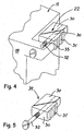
- the terminal box 18 is at both vertical sides 20 at the corner parties provided with four expansion members 22 being designed to fixation the terminal box 18 alone by engagement with the vertical inside walls 6 of the mounting hole 2.
- the rough and uneven bottom part 12 of the mounting hole 12 has no importance or meaning at all for the correct and easy fixation of the terminal box 18 inside the mounting hole 2.
- the terminal box 18 has a lower inlet terminal 24 for an inlet PEX-pipe connection and an outlet terminal 26 for the connection to a valve member or the like of a water installation.
- the expansion members 22 may be easily operated from a front side 28 of the terminal box 18 by means of a simple screw driver.
- each of the expansion members 22 comprises two wedges 30 of similar slope arranged such that the thin end of the wedges 30 overlies, and that both wedges 30 are interconnected by means of a through-going screw 32 available for operation from the front side 28 of the terminal box 18.
- a through-going screw 32 available for operation from the front side 28 of the terminal box 18.
- the expansion member 22 is connected or integrated with the terminal box 18 by means of a thin, flexible wall part 33 extending between the outermost wedge 30 and the corner part of the front side 28 of the terminal box 18.
- the loose expansion members 34 may be provided with attachment means for quick and easy connection to the outside walls of a known terminal box similar to that terminal box 16 shown in Fig. 2.
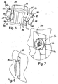
- Figs. 6-8 show a known terminal box 36 during the fixation/mounting in a mounting hole 38 by means of a pair of loose expansion members 40 according to the present invention.
- Fig. 6 is shown how existing lateral protruding, horizontal ribs 42 are used for the receiving of an inner part 44 of the expansion member 40 in such a manner, that a forwardly closed, elongate slot 46, provided in an inner edge of said inner part 44, fits on said rib 42, so that said inner part 44 can be placed on said rib 42 and be fixed behind a circular front part 48 of the terminal box 36.
- said inner part 44 Opposite the elongate slot 46, said inner part 44 has an inclined edge or wedge part 50, along which a loose expansion part 52 may be displaced, as an inner edge part 54 thereof is provided with an elongate slot fitting on said wedge part 50.
- the expansion part 52 is connected to the inner part 44 by means of a screw 56, which may be operated from the front side of the terminal box 36 (Fig. 7) by means of a screwdriver in order to activate the expansion members 40 by displacement of the expansion part 52 along the wedge part 50.
- a screw 56 which may be operated from the front side of the terminal box 36 (Fig. 7) by means of a screwdriver in order to activate the expansion members 40 by displacement of the expansion part 52 along the wedge part 50.
- the expansion part 52 has a corrugated edge surface 58 adapted to engage with an inside, verti-cal wall part of the mounting hole 38.
- the width of which should be about 70 mm, while the depth of the mounting hole 38 should be about 45 mm.
- the expansion member according to the invention may utilize any type of expansion system - by way of example the expansion member may consist of an oval or eccentric member being attached to the respective outsides of the terminal box and being adapted to be turned from the front side thereof by means of a tool engaging in a notch or the like.
- the expansion members may consist of pieces of flexible tube being attached to the opposite outsides of the terminal box and being provided with a cone-shaped member adapted to be forced into said pieces of flexible tube for the fixation of the terminal box against the predominantly vertical inside walls of a mounting hole with said inside walls furthermore being predominantly parallel.
- expansion principle according to the invention using either loose expansion members 34 or integrated expansion members 22 may be used more generally for the purpose of fixation of other types of boxes, mountings and the like between two predominantly vertical or horizontal sides or surfaces.
Landscapes
- Health & Medical Sciences (AREA)
- Life Sciences & Earth Sciences (AREA)
- Engineering & Computer Science (AREA)
- Hydrology & Water Resources (AREA)
- Public Health (AREA)
- Water Supply & Treatment (AREA)
- Connection Or Junction Boxes (AREA)
Applications Claiming Priority (1)
| Application Number | Priority Date | Filing Date | Title |
|---|---|---|---|
| DKPA200501270 | 2005-09-12 |
Publications (1)
| Publication Number | Publication Date |
|---|---|
| EP1762661A1 true EP1762661A1 (de) | 2007-03-14 |
Family
ID=37459541
Family Applications (1)
| Application Number | Title | Priority Date | Filing Date |
|---|---|---|---|
| EP06019081A Withdrawn EP1762661A1 (de) | 2005-09-12 | 2006-09-12 | Anschlusskasten für Wasserinstallation und Klemmelement hierfür |
Country Status (1)
| Country | Link |
|---|---|
| EP (1) | EP1762661A1 (de) |
Citations (11)
| Publication number | Priority date | Publication date | Assignee | Title |
|---|---|---|---|---|
| EP0085329A2 (de) * | 1982-01-29 | 1983-08-10 | Georg Fischer Aktiengesellschaft | Anschlusseinrichtung für Armaturen |
| US4804171A (en) * | 1987-11-06 | 1989-02-14 | Dornfeld Stanley W | Workpiece holding device |
| DE8815170U1 (de) * | 1988-12-06 | 1989-03-23 | Huang, Jue Ping, Hsin-Chuang, Taipei | Einstellbare Befestigungslehre |
| US5797573A (en) * | 1995-01-12 | 1998-08-25 | The Boeing Company | Non-penetration clip attachment |
| DE19715651A1 (de) * | 1997-04-15 | 1998-10-22 | Ortwein Ernst Georg | Vorrichtung zum schall- und wärmedämmenden Anschluß von Sanitärarmaturen etc. |
| US5983923A (en) * | 1996-04-10 | 1999-11-16 | Lsp Products Group, Inc. | Water service box and connectors for PEX pipe |
| DE10035883A1 (de) * | 1999-07-23 | 2001-05-17 | Kirchner Fraenk Rohr | Montageeinrichtung sowie Montagesystem, insbesondere mit dieser |
| WO2001048326A1 (en) * | 1999-12-17 | 2001-07-05 | Tom Christensen | Lead-through device for a pipeline in a building element e.g. a wall and a procedure for such a lead-through |
| DE10053668C1 (de) * | 2000-10-28 | 2002-07-11 | Robert K Wahl | Spannvorrichtung |
| GB2404388A (en) | 2003-07-26 | 2005-02-02 | Toby Richard Treacher | A wedging device for securing lead flashing in a slot between two adjacent rows of brickwork |
| DE102004005161A1 (de) * | 2004-02-02 | 2005-08-18 | Grohe Water Technology Ag & Co. Kg | Einbaukasten für Sanitärarmaturen |
-
2006
- 2006-09-12 EP EP06019081A patent/EP1762661A1/de not_active Withdrawn
Patent Citations (11)
| Publication number | Priority date | Publication date | Assignee | Title |
|---|---|---|---|---|
| EP0085329A2 (de) * | 1982-01-29 | 1983-08-10 | Georg Fischer Aktiengesellschaft | Anschlusseinrichtung für Armaturen |
| US4804171A (en) * | 1987-11-06 | 1989-02-14 | Dornfeld Stanley W | Workpiece holding device |
| DE8815170U1 (de) * | 1988-12-06 | 1989-03-23 | Huang, Jue Ping, Hsin-Chuang, Taipei | Einstellbare Befestigungslehre |
| US5797573A (en) * | 1995-01-12 | 1998-08-25 | The Boeing Company | Non-penetration clip attachment |
| US5983923A (en) * | 1996-04-10 | 1999-11-16 | Lsp Products Group, Inc. | Water service box and connectors for PEX pipe |
| DE19715651A1 (de) * | 1997-04-15 | 1998-10-22 | Ortwein Ernst Georg | Vorrichtung zum schall- und wärmedämmenden Anschluß von Sanitärarmaturen etc. |
| DE10035883A1 (de) * | 1999-07-23 | 2001-05-17 | Kirchner Fraenk Rohr | Montageeinrichtung sowie Montagesystem, insbesondere mit dieser |
| WO2001048326A1 (en) * | 1999-12-17 | 2001-07-05 | Tom Christensen | Lead-through device for a pipeline in a building element e.g. a wall and a procedure for such a lead-through |
| DE10053668C1 (de) * | 2000-10-28 | 2002-07-11 | Robert K Wahl | Spannvorrichtung |
| GB2404388A (en) | 2003-07-26 | 2005-02-02 | Toby Richard Treacher | A wedging device for securing lead flashing in a slot between two adjacent rows of brickwork |
| DE102004005161A1 (de) * | 2004-02-02 | 2005-08-18 | Grohe Water Technology Ag & Co. Kg | Einbaukasten für Sanitärarmaturen |
Similar Documents
| Publication | Publication Date | Title |
|---|---|---|
| EP1443224B1 (de) | Steinpaneelverbinder | |
| WO2003004787A3 (en) | Buck system for concrete structures | |
| EP2093362B1 (de) | Verfahren und Klemmsystem zur Befestigung eines Scharniers oder anderen Beschlags an Profilen für Fenster und Türen | |
| CA2205164C (en) | Door frame | |
| EP0236287A2 (de) | Türeinrichtung | |
| KR20170027218A (ko) | 결합용 홈볼트 | |
| KR101665305B1 (ko) | 건물 외벽용 루버 | |
| KR200224301Y1 (ko) | 건물용 판재 앵커 | |
| KR20180126875A (ko) | 용이하게 재사용되는 방음벽 | |
| EP2180103B1 (de) | Vorrichtung zur verbindung von profilen | |
| EP1722063A2 (de) | Vorrichtung zum Einbau von Rahmen | |
| JP2007239229A (ja) | 開口枠の躯体への取付構造 | |
| KR200402917Y1 (ko) | 거푸집용 간격유지 타이볼트 | |
| KR20090003227U (ko) | 방범창 | |
| KR200255167Y1 (ko) | 벽면 매설용 콘센트 박스의 스페이스 바 | |
| KR200321154Y1 (ko) | 콘크리트 타설용 수도관 유닛 | |
| US20060163247A1 (en) | Securement system for electrical wall box | |
| KR200398652Y1 (ko) | 매입형 전선함의 후면 지지봉 | |
| KR200294096Y1 (ko) | 엔드 커버의 조립구조 | |
| KR20020016480A (ko) | 건물용 판재 앵커 | |
| KR200418941Y1 (ko) | 창호틀 고정용 받침쐐기 | |
| KR100805860B1 (ko) | 앙카 겸용 자재 설치 장치 | |
| AU2006225315B2 (en) | End fitting for an extrusion and fixing method | |
| JP6760852B2 (ja) | 構造体 | |
| JP4791879B2 (ja) | キャップ付きインサート |
Legal Events
| Date | Code | Title | Description |
|---|---|---|---|
| PUAI | Public reference made under article 153(3) epc to a published international application that has entered the european phase |
Free format text: ORIGINAL CODE: 0009012 |
|
| AK | Designated contracting states |
Kind code of ref document: A1 Designated state(s): AT BE BG CH CY CZ DE DK EE ES FI FR GB GR HU IE IS IT LI LT LU LV MC NL PL PT RO SE SI SK TR |
|
| AX | Request for extension of the european patent |
Extension state: AL BA HR MK YU |
|
| 17P | Request for examination filed |
Effective date: 20070908 |
|
| 17Q | First examination report despatched |
Effective date: 20071015 |
|
| AKX | Designation fees paid |
Designated state(s): AT BE BG CH CY CZ DE DK EE ES FI FR GB GR HU IE IS IT LI LT LU LV MC NL PL PT RO SE SI SK TR |
|
| STAA | Information on the status of an ep patent application or granted ep patent |
Free format text: STATUS: THE APPLICATION IS DEEMED TO BE WITHDRAWN |
|
| 18D | Application deemed to be withdrawn |
Effective date: 20100401 |