EP1762665A2 - Wand- oder Deckenkonstruktion in Trockenbauweise - Google Patents
Wand- oder Deckenkonstruktion in Trockenbauweise Download PDFInfo
- Publication number
- EP1762665A2 EP1762665A2 EP06450121A EP06450121A EP1762665A2 EP 1762665 A2 EP1762665 A2 EP 1762665A2 EP 06450121 A EP06450121 A EP 06450121A EP 06450121 A EP06450121 A EP 06450121A EP 1762665 A2 EP1762665 A2 EP 1762665A2
- Authority
- EP
- European Patent Office
- Prior art keywords
- wall
- stone
- ceiling construction
- construction according
- stones
- Prior art date
- Legal status (The legal status is an assumption and is not a legal conclusion. Google has not performed a legal analysis and makes no representation as to the accuracy of the status listed.)
- Granted
Links
- 238000010276 construction Methods 0.000 title claims abstract description 24
- 239000004575 stone Substances 0.000 claims abstract description 40
- 239000000463 material Substances 0.000 claims abstract description 7
- 238000010438 heat treatment Methods 0.000 claims abstract description 5
- 239000002826 coolant Substances 0.000 claims abstract description 4
- 239000002969 artificial stone Substances 0.000 claims abstract description 3
- 239000004927 clay Substances 0.000 claims abstract description 3
- 239000004567 concrete Substances 0.000 claims abstract description 3
- 239000011505 plaster Substances 0.000 claims description 2
- 230000037431 insertion Effects 0.000 claims 2
- 238000003780 insertion Methods 0.000 claims 2
- 239000011449 brick Substances 0.000 claims 1
- 239000004568 cement Substances 0.000 abstract 1
- 238000001816 cooling Methods 0.000 description 3
- 238000005338 heat storage Methods 0.000 description 3
- 238000009434 installation Methods 0.000 description 3
- 230000009191 jumping Effects 0.000 description 2
- 239000011490 mineral wool Substances 0.000 description 2
- 230000002349 favourable effect Effects 0.000 description 1
- 239000010440 gypsum Substances 0.000 description 1
- 229910052602 gypsum Inorganic materials 0.000 description 1
- 238000009413 insulation Methods 0.000 description 1
- 239000002184 metal Substances 0.000 description 1
- 230000000284 resting effect Effects 0.000 description 1
- 239000011232 storage material Substances 0.000 description 1
- 239000012720 thermal barrier coating Substances 0.000 description 1
- 239000002937 thermal insulation foam Substances 0.000 description 1
- 230000036642 wellbeing Effects 0.000 description 1
Images



Classifications
-
- F—MECHANICAL ENGINEERING; LIGHTING; HEATING; WEAPONS; BLASTING
- F24—HEATING; RANGES; VENTILATING
- F24D—DOMESTIC- OR SPACE-HEATING SYSTEMS, e.g. CENTRAL HEATING SYSTEMS; DOMESTIC HOT-WATER SUPPLY SYSTEMS; ELEMENTS OR COMPONENTS THEREFOR
- F24D3/00—Hot-water central heating systems
- F24D3/12—Tube and panel arrangements for ceiling, wall, or underfloor heating
- F24D3/14—Tube and panel arrangements for ceiling, wall, or underfloor heating incorporated in a ceiling, wall or floor
- F24D3/141—Tube mountings specially adapted therefor
- F24D3/142—Tube mountings specially adapted therefor integrated in prefab construction elements
-
- E—FIXED CONSTRUCTIONS
- E04—BUILDING
- E04C—STRUCTURAL ELEMENTS; BUILDING MATERIALS
- E04C2/00—Building elements of relatively thin form for the construction of parts of buildings, e.g. sheet materials, slabs, or panels
- E04C2/30—Building elements of relatively thin form for the construction of parts of buildings, e.g. sheet materials, slabs, or panels characterised by the shape or structure
- E04C2/38—Building elements of relatively thin form for the construction of parts of buildings, e.g. sheet materials, slabs, or panels characterised by the shape or structure with attached ribs, flanges, or the like, e.g. framed panels
- E04C2/386—Building elements of relatively thin form for the construction of parts of buildings, e.g. sheet materials, slabs, or panels characterised by the shape or structure with attached ribs, flanges, or the like, e.g. framed panels with a frame of unreconstituted or laminated wood
-
- F—MECHANICAL ENGINEERING; LIGHTING; HEATING; WEAPONS; BLASTING
- F24—HEATING; RANGES; VENTILATING
- F24D—DOMESTIC- OR SPACE-HEATING SYSTEMS, e.g. CENTRAL HEATING SYSTEMS; DOMESTIC HOT-WATER SUPPLY SYSTEMS; ELEMENTS OR COMPONENTS THEREFOR
- F24D11/00—Central heating systems using heat accumulated in storage masses
- F24D11/002—Central heating systems using heat accumulated in storage masses water heating system
-
- F—MECHANICAL ENGINEERING; LIGHTING; HEATING; WEAPONS; BLASTING
- F24—HEATING; RANGES; VENTILATING
- F24D—DOMESTIC- OR SPACE-HEATING SYSTEMS, e.g. CENTRAL HEATING SYSTEMS; DOMESTIC HOT-WATER SUPPLY SYSTEMS; ELEMENTS OR COMPONENTS THEREFOR
- F24D3/00—Hot-water central heating systems
- F24D3/12—Tube and panel arrangements for ceiling, wall, or underfloor heating
-
- Y—GENERAL TAGGING OF NEW TECHNOLOGICAL DEVELOPMENTS; GENERAL TAGGING OF CROSS-SECTIONAL TECHNOLOGIES SPANNING OVER SEVERAL SECTIONS OF THE IPC; TECHNICAL SUBJECTS COVERED BY FORMER USPC CROSS-REFERENCE ART COLLECTIONS [XRACs] AND DIGESTS
- Y02—TECHNOLOGIES OR APPLICATIONS FOR MITIGATION OR ADAPTATION AGAINST CLIMATE CHANGE
- Y02A—TECHNOLOGIES FOR ADAPTATION TO CLIMATE CHANGE
- Y02A30/00—Adapting or protecting infrastructure or their operation
- Y02A30/24—Structural elements or technologies for improving thermal insulation
-
- Y—GENERAL TAGGING OF NEW TECHNOLOGICAL DEVELOPMENTS; GENERAL TAGGING OF CROSS-SECTIONAL TECHNOLOGIES SPANNING OVER SEVERAL SECTIONS OF THE IPC; TECHNICAL SUBJECTS COVERED BY FORMER USPC CROSS-REFERENCE ART COLLECTIONS [XRACs] AND DIGESTS
- Y02—TECHNOLOGIES OR APPLICATIONS FOR MITIGATION OR ADAPTATION AGAINST CLIMATE CHANGE
- Y02B—CLIMATE CHANGE MITIGATION TECHNOLOGIES RELATED TO BUILDINGS, e.g. HOUSING, HOUSE APPLIANCES OR RELATED END-USER APPLICATIONS
- Y02B30/00—Energy efficient heating, ventilation or air conditioning [HVAC]
-
- Y—GENERAL TAGGING OF NEW TECHNOLOGICAL DEVELOPMENTS; GENERAL TAGGING OF CROSS-SECTIONAL TECHNOLOGIES SPANNING OVER SEVERAL SECTIONS OF THE IPC; TECHNICAL SUBJECTS COVERED BY FORMER USPC CROSS-REFERENCE ART COLLECTIONS [XRACs] AND DIGESTS
- Y02—TECHNOLOGIES OR APPLICATIONS FOR MITIGATION OR ADAPTATION AGAINST CLIMATE CHANGE
- Y02B—CLIMATE CHANGE MITIGATION TECHNOLOGIES RELATED TO BUILDINGS, e.g. HOUSING, HOUSE APPLIANCES OR RELATED END-USER APPLICATIONS
- Y02B80/00—Architectural or constructional elements improving the thermal performance of buildings
Definitions
- the invention relates to a wall or ceiling construction in dry construction, according to the preamble of claim 1.
- a dry construction has the significant advantage of a relatively rapid construction progress with little amount of dirt.
- the disadvantage may be that in the known dry construction methods the wall or ceiling constructions produced have virtually no heat storage capacity.
- Exterior thermal barrier coatings and internal storable layers usually have a favorable effect.
- a wall element for the construction of buildings which has a support frame, which is covered on both sides with Flachpreßspanplatten.
- a layer of mineral wool resting on the Flachpreßspanplatte is provided, which is thinner than the distance between the Flachpreßspanplatten, so that forms an air space.
- a plate made of porous heat storage material is glued as a thermal insulation foam board over a Elastikkleber wearing a plaster on the outside.
- One advantage of the known solution is, inter alia, that the various installations can be laid in a thick, easily worked wall layer, namely the layer of heat-storing material. However, a considerable effort is still required for the installation of a heater or cooling.
- the invention has set itself the goal of creating a wall or ceiling construction in dry construction, in which the installation of a heater or cooling is easier.
- the wall or ceiling with the uprights or beams and the stones attached thereto can be made for the time being and then the installer can insert the tubes, connect with each other and connect to the heating or cooling unit. It is then only to make the panel with the plasterboard or the like.
- the stones have according to a further feature of the invention at their boundary edges each have a step, wherein the height of the steps corresponds approximately to the depth of the grooves. Therefore, the pipes led from one stone to the next stone do not jump out of the main plane of the stones.
- Fig. 1 are on rafters 1 via anchor hanger 2 carrier 3, so-called CD-profiles suspended. Between the beams 3 and the roofing 5 a thermal insulation 4 is inserted. On the supports 3, two plasterboard panels 6 are attached. In the embodiment shown, an additional Sich ceremoniessverschraubung 7 is still arranged.
- supports 9 By means of a riveted connection 8, supports 9, again CD profiles in the example, are suspended. These carry over hooked angled holding profiles stones 10.
- the stones 10 are made of heat-storing material. Plasterboard 6 'cover the stones 10.
- Such a stone 10, as shown in Fig. 4 in plan view, has grooves 11, which extend in the form of an undulating.
- flexible tubes 12 can be inserted for the flow of a heating or cooling medium.
- the grooves 11 are undercut at the respective peaks of the waves. As a result, jumping out of the flexible tubes 12 is prevented.
- the stones 10 have at their boundary edges steps 13 whose height corresponds substantially to the depth of the grooves 11. This makes it possible to guide flexible tubes 12 from one stone 10 to the adjacent stone 10 without these tubes projecting from the lower main plane of the stones 10. Where there are no tubes 12 in the space between two stones 10, a strip 14 is inserted from plasterboard.
- each stone has a respective over half the stone width reaching projection 15, wherein the two projections 15 are offset by half the stone width from each other.
- Each of these projections 15 engages in a recess 16 of the neighboring stone.
- a revision stone 17 is used in the invention.
- This revision stone 17 has blind holes 18, in the holder for the flexible tubes 12 can be used.
- the revision stone 17 has two continuous strips 19, with which it rests on the stones lying next to it and can be easily lifted upwards.
- baffle 20 It may also be provided a baffle 20, the bump 21 and transverse guides 22 has.
- the bumps 21 allow a looping of the flexible tubes 12, the guides 22 a deflection of the flexible tubes 12 perpendicular to their previous course. In order to prevent jumping out of the flexible tubes 12, the bumps are provided with undercut grooves 21 '.
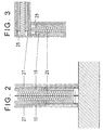
- Figs. 2 and 3 illustrate a metal stud wall.
- the studs 25 are CW profiles in this case.
- a mineral wool insert 26 is arranged in the middle of the wall and then the stones 10 are made of heat-storing material on both sides.
- Plasterboard panels 27 cover the stones 10 on both sides of the wall.
- a revision stone 28 is shown for a wall construction.
- two sliding elements 29 and 30 are provided which are mutually displaceable and thereby od access to underlying terminals.
- two sliding elements 29 and 30 are provided which are mutually displaceable and thereby od access to underlying terminals.
Landscapes
- Engineering & Computer Science (AREA)
- Physics & Mathematics (AREA)
- Thermal Sciences (AREA)
- Chemical & Material Sciences (AREA)
- Combustion & Propulsion (AREA)
- Mechanical Engineering (AREA)
- General Engineering & Computer Science (AREA)
- Architecture (AREA)
- Civil Engineering (AREA)
- Structural Engineering (AREA)
- Building Environments (AREA)
- Finishing Walls (AREA)
Abstract
Description
- Die Erfindung bezieht sich auf eine Wand- oder Deckenkonstruktion in Trockenbauweise, entsprechend dem Oberbegriff des Anspruches 1.
- Eine Trockenbauweise hat den wesentlichen Vorteil eines verhältnismäßig raschen Baufortschrittes bei wenig Schmutzanfall. Nachteilig kann sein, dass bei den bekannten Trockenbauweisen die hergestellten Wand- oder Deckenkonstruktionen praktisch keine Wärmespeicherfähigkeit besitzen.
- Die Wärmespeicherfähigkeit von Bauteilen kann jedoch für das Wohlempfinden der Bewohner und Nutzer von Räumen eine große Bedeutung haben. Außen liegende Wärmedämmschichten und innen liegende speicherfähige Schichten wirken sich in der Regel günstig aus.
- In der
AT 403 936 - Vorteil der bekannten Lösung soll unter anderem sein, dass die verschiedenen Installationen in einer dicken, leicht zu bearbeitenden Wandschicht, nämlich der Lage aus wärmespeicherndem Werkstoff, verlegt werden können. Allerdings ist noch immer ein beträchtlicher Aufwand für die Montage einer Heizung oder Kühlung erforderlich.
- Die Erfindung hat es sich zum Ziel gesetzt, eine Wand- oder Deckenkonstruktion in Trockenbauweise zu schaffen, bei der die Montage einer Heizung oder Kühlung einfacher ist.
- Erreicht wird dies dadurch, dass die Elemente aus wärmespeicherndem Material Steine aus gebranntem Ton, aus Gips, aus Beton oder Kunststeine sind und Nuten zum Einlegen von insbesondere flexiblen Rohren für den Durchfluß eines Heiz- oder Kühlmediums aufweisen.
- Bei einer solchen Ausführungsform kann die Wand oder Decke mit den Ständern oder Trägern und den daran befestigten Steinen vorerst hergestellt werden und anschließend kann der Installateur die Rohre einlegen, miteinander verbinden sowie an das Heiz- oder Kühlaggregat anschließen. Es ist dann nur mehr die Verkleidung mit den Gipskartonplatten oder dergleichen herzustellen.
- Damit die flexiblen Rohre von einem Stein zu einem der danebenliegenden Steine mit etwa parallel liegenden Nuten geführt werden können, besitzen die Steine nach einem weiteren Erfindungsmerkmal an ihren Begrenzungskanten je eine Stufe, wobei die Höhe der Stufen etwa der Tiefe der Nuten entspricht. Die von einem Stein zum benachbarten Stein geführten Rohre springen daher nicht aus der Hauptebene der Steine hervor.
- Weitere Merkmale der Erfindung sind in den Unteransprüchen gekennzeichnet.
- Nachstehend ist die Erfindung anhand von in den Zeichnungen dargestellten Ausführungsbeispielen näher beschrieben, ohne auf diese Beispiele beschränkt zu sein.
Dabei zeigen: - Fig. 1
- einen Schnitt durch eine erfindungsgemäß ausgebildete Deckenkonstruktion;
- Fig. 2
- den unteren Teil einer Wandkonstruktion nach der Erfindung;
- Fig. 3
- den Anschluß zweier senkrecht zueinander verlaufenden Wandkonstruktionen;
- Fig. 4
- eine Draufsicht auf nebeneinander liegende verschiedene Steine vor ihrem Anschluß;
- Fig. 5
- einen Schnitt der Steine nach Fig. 4;
- Fig. 6
- eine Draufsicht auf einen Revisionsstein;
- Fig. 7
- eine Seitenansicht auf den Revisionsstein nach Fig. 6.
- Gemäß Fig. 1 sind an Sparren 1 über Ankerhänger 2 Träger 3, sogenannte CD-Profile, aufgehängt. Zwischen den Trägern 3 und der Dachdeckung 5 ist eine Wärmedämmung 4 eingelegt. An den Trägern 3 sind zwei Gipskartonplatten 6 befestigt. Im gezeigten Ausführungsbeispiel ist noch eine zusätzliche Sicherungsverschraubung 7 angeordnet.
- Über eine Nietverbindung 8 sind Träger 9, im Beispiel wieder CD-Profile, aufgehängt. Diese tragen über eingehakte abgewinkelte Halteprofile Steine 10. Die Steine 10 bestehen aus wärmespeicherndem Material. Gipskartonplatten 6' decken die Steine 10 ab.
- Ein solcher Stein 10, wie er in Fig. 4 in Draufsicht dargestellt ist, besitzt Nuten 11, die im Ausführungsbeispiel wellenförmig verlaufen. In die Nuten 11 können flexible Rohre 12 für den Durchfluß eines Heiz- oder Kühlmediums eingelegt werden. Wie strichliert dargestellt und mit 11' bezeichnet ist, sind die Nuten 11 an den jeweiligen Scheitelpunkten der Wellen hinterschnitten. Dadurch wird ein Herausspringen der flexiblen Rohre 12 verhindert.
- Die Steine 10 besitzen an ihren Begrenzungskanten Stufen 13, deren Höhe im wesentlichen der Tiefe der Nuten 11 entspricht. Dadurch ist es möglich, flexible Rohre 12 von einem Stein 10 zum benachbarten Stein 10 zu führen, ohne dass diese Rohre aus der unteren Hauptebene der Steine 10 vorspringen. Dort, wo keine Rohre 12 in dem Zwischenraum zwischen zwei Steinen 10 liegen, ist ein Streifen 14 aus Gipskarton eingelegt.
- Um hintereinander liegende Steine verbinden zu können, besitzt jeder Stein einen jeweils über die halbe Steinbreite reichenden Vorsprung 15, wobei die beiden Vorsprünge 15 um die halbe Steinbreite gegeneinander versetzt sind. Jeder dieser Vorsprünge 15 greift in eine Vertiefung 16 des Nachbarsteines ein.
- Unter der Decke befinden sich zuweilen Anschlüsse oder Betätigungsorgane, zu denen ein Zugang möglich sein muß. Um einen solchen Zugang zu erreichen, wird im Rahmen der Erfindung ein Revisionsstein 17 eingesetzt. Dieser Revisionsstein 17 besitzt Sackbohrungen 18, in die Halter für die flexiblen Rohre 12 eingesetzt werden können. Der Revisionsstein 17 besitzt zwei durchgehende Leisten 19, mit denen er auf den daneben liegenden Steinen aufliegt und leicht nach oben abgehoben werden kann.
- Es kann ferner ein Umlenkstein 20 vorgesehen sein, der Höcker 21 sowie quer verlaufende Führungen 22 besitzt.
- Die Höcker 21 ermöglichen eine Schleifenbildung der flexiblen Rohre 12, die Führungen 22 eine Ablenkung der flexiblen Rohre 12 senkrecht zu ihrem bisherigen Verlauf. Um ein Herausspringen der flexiblen Rohre 12 zu verhindern, sind die Höcker mit hinterschnittenen Nuten 21' versehen.
- In Fig. 4 sind beim Umlenkstein 20 die Mittellinien von eingelegten flexiblen Rohren eingezeichnet.
- Die Fig. 2 und 3 stellen eine Metallständerwand dar. Die Ständer 25 sind in diesem Falle CW-Profile. Eine Mineralwolleinlage 26 ist in der Mitte der Wand angeordnet und anschließend befinden sich beidseitig die Steine 10 aus wärmespeicherndem Material. Gipskartonplatten 27 decken die Steine 10 an beiden Seiten der Wand ab.
- In den Fig. 6 und 7 ist ein Revisionsstein 28 für eine Wandkonstruktion dargestellt. Bei diesem Revisionsstein 28 sind zwei Schiebeelemente 29 und 30 vorgesehen, die gegeneinander verschiebbar sind und dadurch ein Zugang zu darunter liegenden Anschlüssen od. dgl. möglich ist.
Claims (7)
- Wand- oder Deckenkonstruktion in Trockenbauweise, wobei an Ständern (25) oder Trägern (9) Gipskartonplatten (6, 6', 27) oder dergleichen befestigt sind und hinter den Gipskartonplatten (6, 6', 27) oder dergleichen Elemente (10) aus wärmespeicherndem Material angeordnet sind, dadurch gekennzeichnet, dass die Elemente aus wärmespeicherndem Material Steine (10) aus gebranntem Ton, aus Gips, aus Beton oder Kunststeine sind und Nuten (11) zum Einlegen von insbesondere flexiblen Rohren (12) für den Durchfluß eines Heiz- oder Kühlmediums aufweisen.
- Wand- oder Deckenkonstruktion nach Anspruch 1, dadurch gekennzeichnet, dass die Steine (10) an ihren Begrenzungskanten je eine Stufe (13) besitzen, wobei die Höhe der Stufen (13) etwa der Tiefe der Nuten (11) entspricht.
- Wand- oder Deckenkonstruktion nach Anspruch 1 oder 2, dadurch gekennzeichnet, dass ein Revisionsstein (17) um seine Mitte herumgeführte Sackbohrungen (18) zum Einlegen von insbesondere flexiblen Rohren (12) mittels Haltern aufweist.
- Wand- oder Deckenkonstruktion nach einem der Ansprüche 1 bis 3, dadurch gekennzeichnet, dass ein Stein (20) Höcker (21) zum Umkehren von flexiblen Rohren (12) aufweist.
- Wand- oder Deckenkonstruktion nach Anspruch 4, dadurch gekennzeichnet, dass die Höcker (21) hinterschnittene Nuten (21') zum Einlegen der flexiblen Rohre (12) aufweist.
- Wand- oder Deckenkonstruktion nach einem der Ansprüche 1 bis 5, dadurch gekennzeichnet, dass ein Stein seitwärts gerichtete Führungen (22) zum Einlegen von flexiblen Rohren (12) aufweist.
- Wand- oder Deckenkonstruktion nach einem der Ansprüche 1 bis 6, dadurch gekennzeichnet, dass ein Revisionsstein (28) mindestens eine Öffnung aufweist, die durch ein verschiebbares Element (29, 30) verschließbar ist.
Applications Claiming Priority (1)
| Application Number | Priority Date | Filing Date | Title |
|---|---|---|---|
| AT0149705A AT502704B1 (de) | 2005-09-12 | 2005-09-12 | Wand- oder deckenkonstruktion in trockenbauweise |
Publications (3)
| Publication Number | Publication Date |
|---|---|
| EP1762665A2 true EP1762665A2 (de) | 2007-03-14 |
| EP1762665A3 EP1762665A3 (de) | 2008-05-28 |
| EP1762665B1 EP1762665B1 (de) | 2014-08-06 |
Family
ID=37499721
Family Applications (1)
| Application Number | Title | Priority Date | Filing Date |
|---|---|---|---|
| EP06450121.6A Active EP1762665B1 (de) | 2005-09-12 | 2006-09-06 | Wand- oder Deckenkonstruktion in Trockenbauweise |
Country Status (2)
| Country | Link |
|---|---|
| EP (1) | EP1762665B1 (de) |
| AT (1) | AT502704B1 (de) |
Cited By (2)
| Publication number | Priority date | Publication date | Assignee | Title |
|---|---|---|---|---|
| AT13286U1 (de) * | 2012-04-16 | 2013-10-15 | Herbert Renner Handels Gmbh & Co Kg | Abgehängte Kühl-/Heizdecke |
| EP2105675A3 (de) * | 2008-03-28 | 2014-04-16 | MERO-TSK International GmbH & Co. KG | Flächentemperierungsaufbau |
Citations (1)
| Publication number | Priority date | Publication date | Assignee | Title |
|---|---|---|---|---|
| AT403936B (de) | 1993-06-29 | 1998-06-25 | Wolf Systembau Gmbh & Co Kg | Wandelement |
Family Cites Families (4)
| Publication number | Priority date | Publication date | Assignee | Title |
|---|---|---|---|---|
| DE7723097U1 (de) * | 1977-07-27 | 1980-11-27 | 4434 Ochtrup | Einbauelement für Flüssigkeits-Flächenheixungen |
| DE4225945A1 (de) * | 1992-08-06 | 1994-02-10 | Herrmann Gmbh & Co Kg | Vorrichtung zur Aufnahme von heizungs- und/oder lüftungstechnischen Elementen |
| DE19962088A1 (de) * | 1999-12-21 | 2001-07-12 | Andreas Naumann | Wandkonstruktion, Wandbauteil, Wand zur Errichtung von Bauwerken und Verfahren zur Herstellung derselben |
| DE202004002127U1 (de) * | 2004-02-12 | 2004-08-26 | Loss, Hans | Beheizbarer oder kühlbarer Boden- oder Wandaufbau |
-
2005
- 2005-09-12 AT AT0149705A patent/AT502704B1/de not_active IP Right Cessation
-
2006
- 2006-09-06 EP EP06450121.6A patent/EP1762665B1/de active Active
Patent Citations (1)
| Publication number | Priority date | Publication date | Assignee | Title |
|---|---|---|---|---|
| AT403936B (de) | 1993-06-29 | 1998-06-25 | Wolf Systembau Gmbh & Co Kg | Wandelement |
Cited By (2)
| Publication number | Priority date | Publication date | Assignee | Title |
|---|---|---|---|---|
| EP2105675A3 (de) * | 2008-03-28 | 2014-04-16 | MERO-TSK International GmbH & Co. KG | Flächentemperierungsaufbau |
| AT13286U1 (de) * | 2012-04-16 | 2013-10-15 | Herbert Renner Handels Gmbh & Co Kg | Abgehängte Kühl-/Heizdecke |
Also Published As
| Publication number | Publication date |
|---|---|
| AT502704B1 (de) | 2008-07-15 |
| AT502704A1 (de) | 2007-05-15 |
| EP1762665B1 (de) | 2014-08-06 |
| EP1762665A3 (de) | 2008-05-28 |
Similar Documents
| Publication | Publication Date | Title |
|---|---|---|
| DE3016963A1 (de) | Einsetz-baustein fuer gebaeudewaende und verfahren zum konstruieren von gebaeuden unter verwendung derartiger bausteine | |
| CH666307A5 (de) | Trennelement fuer betonplatten. | |
| EP0927323A1 (de) | Kühldecke, elemente für kühldecke und kühlrohrmatte zur anwendung bei einer kühldecke | |
| DE10222907A1 (de) | Gebäudefundament und dessen Verfahren zur Anwendung | |
| AT502704B1 (de) | Wand- oder deckenkonstruktion in trockenbauweise | |
| EP0150242B1 (de) | Fertigteil zum Aufbau eines über seine Wände klimatisierten Gebäudes | |
| DE4434499A1 (de) | Deckenplatte für die Herstellung von Geschoßdecken | |
| DE2603361A1 (de) | Elementierte sanitaeranlagen fuer den nachtraeglichen einbau | |
| DE19848003A1 (de) | Betondecken- und Wandelement | |
| EP0227937A1 (de) | Balkon zum nachträglichen Anbringen an ein Gebäude | |
| DE4444921C2 (de) | Raumbausteinsystem für das Errichten von Bauwerken | |
| DE202014004059U1 (de) | Fertigkeller | |
| AT2945U1 (de) | Formstein zur herstellung von mauerelementen | |
| DE29516947U1 (de) | Vorgefertigtes Bauelement für Decken/Böden/Wände eines Gebäudes mit Flächenheizungs- und/oder Kühlungssystem | |
| DE3315007A1 (de) | Verfahren zum bauen von wohnhaeusern und nutzgebaeuden | |
| DE102004011902B3 (de) | Verfahren zur Herstellung einer Gebäude-Etagen-Decke | |
| DE19855066C1 (de) | Anordnung zur Verbindung von Naßstrecken und/oder Sanitäreinrichtungen mit Rohrschächten im Zuge von Grundrißänderungen beim Umbau von bestehenden Typbauten | |
| DE8421785U1 (de) | Installationsschacht | |
| AT518974B1 (de) | Schalungsschoner mit Verteiler | |
| AT411540B (de) | Ziegeldecke | |
| DE102016112459A1 (de) | Baukastensystem zur Erstellung eines Fertighauses und Verfahren zu dessen Herstellung | |
| DE20009653U1 (de) | Vorgefertigte Betonplatte und Verschalung zu ihrer Herstellung | |
| AT352958B (de) | Vorgefertigtes deckenelement | |
| EP0770827A1 (de) | Temperierbare Wand und Verfahren zur Herstellung der Wand | |
| DE9105949U1 (de) | Vorgefertigter Modul zur Herstellung von Bauwerken und Gebäuden |
Legal Events
| Date | Code | Title | Description |
|---|---|---|---|
| PUAI | Public reference made under article 153(3) epc to a published international application that has entered the european phase |
Free format text: ORIGINAL CODE: 0009012 |
|
| AK | Designated contracting states |
Kind code of ref document: A2 Designated state(s): AT BE BG CH CY CZ DE DK EE ES FI FR GB GR HU IE IS IT LI LT LU LV MC NL PL PT RO SE SI SK TR |
|
| AX | Request for extension of the european patent |
Extension state: AL BA HR MK YU |
|
| PUAL | Search report despatched |
Free format text: ORIGINAL CODE: 0009013 |
|
| AK | Designated contracting states |
Kind code of ref document: A3 Designated state(s): AT BE BG CH CY CZ DE DK EE ES FI FR GB GR HU IE IS IT LI LT LU LV MC NL PL PT RO SE SI SK TR |
|
| AX | Request for extension of the european patent |
Extension state: AL BA HR MK RS |
|
| 17P | Request for examination filed |
Effective date: 20080823 |
|
| AKX | Designation fees paid |
Designated state(s): AT BE BG CH CY CZ DE DK EE ES FI FR GB GR HU IE IS IT LI LT LU LV MC NL PL PT RO SE SI SK TR |
|
| AXX | Extension fees paid |
Extension state: HR Payment date: 20080823 |
|
| 17Q | First examination report despatched |
Effective date: 20130712 |
|
| GRAP | Despatch of communication of intention to grant a patent |
Free format text: ORIGINAL CODE: EPIDOSNIGR1 |
|
| INTG | Intention to grant announced |
Effective date: 20140417 |
|
| GRAS | Grant fee paid |
Free format text: ORIGINAL CODE: EPIDOSNIGR3 |
|
| GRAA | (expected) grant |
Free format text: ORIGINAL CODE: 0009210 |
|
| AK | Designated contracting states |
Kind code of ref document: B1 Designated state(s): AT BE BG CH CY CZ DE DK EE ES FI FR GB GR HU IE IS IT LI LT LU LV MC NL PL PT RO SE SI SK TR |
|
| AX | Request for extension of the european patent |
Extension state: HR |
|
| REG | Reference to a national code |
Ref country code: GB Ref legal event code: FG4D Free format text: NOT ENGLISH |
|
| REG | Reference to a national code |
Ref country code: CH Ref legal event code: EP Ref country code: AT Ref legal event code: REF Ref document number: 681151 Country of ref document: AT Kind code of ref document: T Effective date: 20140815 |
|
| REG | Reference to a national code |
Ref country code: IE Ref legal event code: FG4D Free format text: LANGUAGE OF EP DOCUMENT: GERMAN |
|
| REG | Reference to a national code |
Ref country code: DE Ref legal event code: R096 Ref document number: 502006013895 Country of ref document: DE Effective date: 20140918 |
|
| REG | Reference to a national code |
Ref country code: NL Ref legal event code: VDEP Effective date: 20140806 |
|
| REG | Reference to a national code |
Ref country code: LT Ref legal event code: MG4D |
|
| PG25 | Lapsed in a contracting state [announced via postgrant information from national office to epo] |
Ref country code: PT Free format text: LAPSE BECAUSE OF FAILURE TO SUBMIT A TRANSLATION OF THE DESCRIPTION OR TO PAY THE FEE WITHIN THE PRESCRIBED TIME-LIMIT Effective date: 20141209 Ref country code: FI Free format text: LAPSE BECAUSE OF FAILURE TO SUBMIT A TRANSLATION OF THE DESCRIPTION OR TO PAY THE FEE WITHIN THE PRESCRIBED TIME-LIMIT Effective date: 20140806 Ref country code: BG Free format text: LAPSE BECAUSE OF FAILURE TO SUBMIT A TRANSLATION OF THE DESCRIPTION OR TO PAY THE FEE WITHIN THE PRESCRIBED TIME-LIMIT Effective date: 20141106 Ref country code: LT Free format text: LAPSE BECAUSE OF FAILURE TO SUBMIT A TRANSLATION OF THE DESCRIPTION OR TO PAY THE FEE WITHIN THE PRESCRIBED TIME-LIMIT Effective date: 20140806 Ref country code: SE Free format text: LAPSE BECAUSE OF FAILURE TO SUBMIT A TRANSLATION OF THE DESCRIPTION OR TO PAY THE FEE WITHIN THE PRESCRIBED TIME-LIMIT Effective date: 20140806 Ref country code: ES Free format text: LAPSE BECAUSE OF FAILURE TO SUBMIT A TRANSLATION OF THE DESCRIPTION OR TO PAY THE FEE WITHIN THE PRESCRIBED TIME-LIMIT Effective date: 20140806 Ref country code: GR Free format text: LAPSE BECAUSE OF FAILURE TO SUBMIT A TRANSLATION OF THE DESCRIPTION OR TO PAY THE FEE WITHIN THE PRESCRIBED TIME-LIMIT Effective date: 20141107 |
|
| PG25 | Lapsed in a contracting state [announced via postgrant information from national office to epo] |
Ref country code: CY Free format text: LAPSE BECAUSE OF FAILURE TO SUBMIT A TRANSLATION OF THE DESCRIPTION OR TO PAY THE FEE WITHIN THE PRESCRIBED TIME-LIMIT Effective date: 20140806 Ref country code: NL Free format text: LAPSE BECAUSE OF FAILURE TO SUBMIT A TRANSLATION OF THE DESCRIPTION OR TO PAY THE FEE WITHIN THE PRESCRIBED TIME-LIMIT Effective date: 20140806 Ref country code: IS Free format text: LAPSE BECAUSE OF FAILURE TO SUBMIT A TRANSLATION OF THE DESCRIPTION OR TO PAY THE FEE WITHIN THE PRESCRIBED TIME-LIMIT Effective date: 20141206 Ref country code: LV Free format text: LAPSE BECAUSE OF FAILURE TO SUBMIT A TRANSLATION OF THE DESCRIPTION OR TO PAY THE FEE WITHIN THE PRESCRIBED TIME-LIMIT Effective date: 20140806 Ref country code: PL Free format text: LAPSE BECAUSE OF FAILURE TO SUBMIT A TRANSLATION OF THE DESCRIPTION OR TO PAY THE FEE WITHIN THE PRESCRIBED TIME-LIMIT Effective date: 20140806 |
|
| PG25 | Lapsed in a contracting state [announced via postgrant information from national office to epo] |
Ref country code: CZ Free format text: LAPSE BECAUSE OF FAILURE TO SUBMIT A TRANSLATION OF THE DESCRIPTION OR TO PAY THE FEE WITHIN THE PRESCRIBED TIME-LIMIT Effective date: 20140806 Ref country code: IT Free format text: LAPSE BECAUSE OF FAILURE TO SUBMIT A TRANSLATION OF THE DESCRIPTION OR TO PAY THE FEE WITHIN THE PRESCRIBED TIME-LIMIT Effective date: 20140806 Ref country code: RO Free format text: LAPSE BECAUSE OF FAILURE TO SUBMIT A TRANSLATION OF THE DESCRIPTION OR TO PAY THE FEE WITHIN THE PRESCRIBED TIME-LIMIT Effective date: 20140806 Ref country code: SK Free format text: LAPSE BECAUSE OF FAILURE TO SUBMIT A TRANSLATION OF THE DESCRIPTION OR TO PAY THE FEE WITHIN THE PRESCRIBED TIME-LIMIT Effective date: 20140806 Ref country code: DK Free format text: LAPSE BECAUSE OF FAILURE TO SUBMIT A TRANSLATION OF THE DESCRIPTION OR TO PAY THE FEE WITHIN THE PRESCRIBED TIME-LIMIT Effective date: 20140806 Ref country code: EE Free format text: LAPSE BECAUSE OF FAILURE TO SUBMIT A TRANSLATION OF THE DESCRIPTION OR TO PAY THE FEE WITHIN THE PRESCRIBED TIME-LIMIT Effective date: 20140806 |
|
| REG | Reference to a national code |
Ref country code: CH Ref legal event code: PL |
|
| REG | Reference to a national code |
Ref country code: DE Ref legal event code: R097 Ref document number: 502006013895 Country of ref document: DE |
|
| PG25 | Lapsed in a contracting state [announced via postgrant information from national office to epo] |
Ref country code: MC Free format text: LAPSE BECAUSE OF FAILURE TO SUBMIT A TRANSLATION OF THE DESCRIPTION OR TO PAY THE FEE WITHIN THE PRESCRIBED TIME-LIMIT Effective date: 20140806 |
|
| PLBE | No opposition filed within time limit |
Free format text: ORIGINAL CODE: 0009261 |
|
| STAA | Information on the status of an ep patent application or granted ep patent |
Free format text: STATUS: NO OPPOSITION FILED WITHIN TIME LIMIT |
|
| REG | Reference to a national code |
Ref country code: IE Ref legal event code: MM4A |
|
| PG25 | Lapsed in a contracting state [announced via postgrant information from national office to epo] |
Ref country code: BE Free format text: LAPSE BECAUSE OF NON-PAYMENT OF DUE FEES Effective date: 20140930 |
|
| 26N | No opposition filed |
Effective date: 20150507 |
|
| GBPC | Gb: european patent ceased through non-payment of renewal fee |
Effective date: 20141106 |
|
| PG25 | Lapsed in a contracting state [announced via postgrant information from national office to epo] |
Ref country code: CH Free format text: LAPSE BECAUSE OF NON-PAYMENT OF DUE FEES Effective date: 20140930 Ref country code: LI Free format text: LAPSE BECAUSE OF NON-PAYMENT OF DUE FEES Effective date: 20140930 |
|
| PG25 | Lapsed in a contracting state [announced via postgrant information from national office to epo] |
Ref country code: IE Free format text: LAPSE BECAUSE OF NON-PAYMENT OF DUE FEES Effective date: 20140906 |
|
| REG | Reference to a national code |
Ref country code: FR Ref legal event code: PLFP Year of fee payment: 10 |
|
| PG25 | Lapsed in a contracting state [announced via postgrant information from national office to epo] |
Ref country code: GB Free format text: LAPSE BECAUSE OF NON-PAYMENT OF DUE FEES Effective date: 20141106 |
|
| PGFP | Annual fee paid to national office [announced via postgrant information from national office to epo] |
Ref country code: DE Payment date: 20150910 Year of fee payment: 10 |
|
| REG | Reference to a national code |
Ref country code: AT Ref legal event code: MM01 Ref document number: 681151 Country of ref document: AT Kind code of ref document: T Effective date: 20140906 |
|
| PG25 | Lapsed in a contracting state [announced via postgrant information from national office to epo] |
Ref country code: SI Free format text: LAPSE BECAUSE OF FAILURE TO SUBMIT A TRANSLATION OF THE DESCRIPTION OR TO PAY THE FEE WITHIN THE PRESCRIBED TIME-LIMIT Effective date: 20140806 |
|
| PGFP | Annual fee paid to national office [announced via postgrant information from national office to epo] |
Ref country code: FR Payment date: 20150914 Year of fee payment: 10 |
|
| PG25 | Lapsed in a contracting state [announced via postgrant information from national office to epo] |
Ref country code: AT Free format text: LAPSE BECAUSE OF NON-PAYMENT OF DUE FEES Effective date: 20140906 |
|
| PG25 | Lapsed in a contracting state [announced via postgrant information from national office to epo] |
Ref country code: HU Free format text: LAPSE BECAUSE OF FAILURE TO SUBMIT A TRANSLATION OF THE DESCRIPTION OR TO PAY THE FEE WITHIN THE PRESCRIBED TIME-LIMIT; INVALID AB INITIO Effective date: 20060906 Ref country code: TR Free format text: LAPSE BECAUSE OF FAILURE TO SUBMIT A TRANSLATION OF THE DESCRIPTION OR TO PAY THE FEE WITHIN THE PRESCRIBED TIME-LIMIT Effective date: 20140806 Ref country code: LU Free format text: LAPSE BECAUSE OF NON-PAYMENT OF DUE FEES Effective date: 20140906 |
|
| REG | Reference to a national code |
Ref country code: DE Ref legal event code: R119 Ref document number: 502006013895 Country of ref document: DE |
|
| REG | Reference to a national code |
Ref country code: FR Ref legal event code: ST Effective date: 20170531 |
|
| PG25 | Lapsed in a contracting state [announced via postgrant information from national office to epo] |
Ref country code: DE Free format text: LAPSE BECAUSE OF NON-PAYMENT OF DUE FEES Effective date: 20170401 Ref country code: FR Free format text: LAPSE BECAUSE OF NON-PAYMENT OF DUE FEES Effective date: 20160930 |