EP1762732A1 - Palier de vilebrequin - Google Patents
Palier de vilebrequin Download PDFInfo
- Publication number
- EP1762732A1 EP1762732A1 EP06022371A EP06022371A EP1762732A1 EP 1762732 A1 EP1762732 A1 EP 1762732A1 EP 06022371 A EP06022371 A EP 06022371A EP 06022371 A EP06022371 A EP 06022371A EP 1762732 A1 EP1762732 A1 EP 1762732A1
- Authority
- EP
- European Patent Office
- Prior art keywords
- bearing
- shell
- flange
- thrust
- bearing shell
- Prior art date
- Legal status (The legal status is an assumption and is not a legal conclusion. Google has not performed a legal analysis and makes no representation as to the accuracy of the status listed.)
- Withdrawn
Links
Images

Classifications
-
- F—MECHANICAL ENGINEERING; LIGHTING; HEATING; WEAPONS; BLASTING
- F16—ENGINEERING ELEMENTS AND UNITS; GENERAL MEASURES FOR PRODUCING AND MAINTAINING EFFECTIVE FUNCTIONING OF MACHINES OR INSTALLATIONS; THERMAL INSULATION IN GENERAL
- F16C—SHAFTS; FLEXIBLE SHAFTS; ELEMENTS OR CRANKSHAFT MECHANISMS; ROTARY BODIES OTHER THAN GEARING ELEMENTS; BEARINGS
- F16C43/00—Assembling bearings
- F16C43/02—Assembling sliding-contact bearings
-
- F—MECHANICAL ENGINEERING; LIGHTING; HEATING; WEAPONS; BLASTING
- F16—ENGINEERING ELEMENTS AND UNITS; GENERAL MEASURES FOR PRODUCING AND MAINTAINING EFFECTIVE FUNCTIONING OF MACHINES OR INSTALLATIONS; THERMAL INSULATION IN GENERAL
- F16C—SHAFTS; FLEXIBLE SHAFTS; ELEMENTS OR CRANKSHAFT MECHANISMS; ROTARY BODIES OTHER THAN GEARING ELEMENTS; BEARINGS
- F16C17/00—Sliding-contact bearings for exclusively rotary movement
- F16C17/04—Sliding-contact bearings for exclusively rotary movement for axial load only
-
- F—MECHANICAL ENGINEERING; LIGHTING; HEATING; WEAPONS; BLASTING
- F16—ENGINEERING ELEMENTS AND UNITS; GENERAL MEASURES FOR PRODUCING AND MAINTAINING EFFECTIVE FUNCTIONING OF MACHINES OR INSTALLATIONS; THERMAL INSULATION IN GENERAL
- F16C—SHAFTS; FLEXIBLE SHAFTS; ELEMENTS OR CRANKSHAFT MECHANISMS; ROTARY BODIES OTHER THAN GEARING ELEMENTS; BEARINGS
- F16C17/00—Sliding-contact bearings for exclusively rotary movement
- F16C17/10—Sliding-contact bearings for exclusively rotary movement for both radial and axial load
-
- F—MECHANICAL ENGINEERING; LIGHTING; HEATING; WEAPONS; BLASTING
- F16—ENGINEERING ELEMENTS AND UNITS; GENERAL MEASURES FOR PRODUCING AND MAINTAINING EFFECTIVE FUNCTIONING OF MACHINES OR INSTALLATIONS; THERMAL INSULATION IN GENERAL
- F16C—SHAFTS; FLEXIBLE SHAFTS; ELEMENTS OR CRANKSHAFT MECHANISMS; ROTARY BODIES OTHER THAN GEARING ELEMENTS; BEARINGS
- F16C9/00—Bearings for crankshafts or connecting-rods; Attachment of connecting-rods
- F16C9/02—Crankshaft bearings
-
- F—MECHANICAL ENGINEERING; LIGHTING; HEATING; WEAPONS; BLASTING
- F16—ENGINEERING ELEMENTS AND UNITS; GENERAL MEASURES FOR PRODUCING AND MAINTAINING EFFECTIVE FUNCTIONING OF MACHINES OR INSTALLATIONS; THERMAL INSULATION IN GENERAL
- F16C—SHAFTS; FLEXIBLE SHAFTS; ELEMENTS OR CRANKSHAFT MECHANISMS; ROTARY BODIES OTHER THAN GEARING ELEMENTS; BEARINGS
- F16C2226/00—Joining parts; Fastening; Assembling or mounting parts
- F16C2226/30—Material joints
- F16C2226/36—Material joints by welding
-
- F—MECHANICAL ENGINEERING; LIGHTING; HEATING; WEAPONS; BLASTING
- F16—ENGINEERING ELEMENTS AND UNITS; GENERAL MEASURES FOR PRODUCING AND MAINTAINING EFFECTIVE FUNCTIONING OF MACHINES OR INSTALLATIONS; THERMAL INSULATION IN GENERAL
- F16C—SHAFTS; FLEXIBLE SHAFTS; ELEMENTS OR CRANKSHAFT MECHANISMS; ROTARY BODIES OTHER THAN GEARING ELEMENTS; BEARINGS
- F16C2360/00—Engines or pumps
- F16C2360/22—Internal combustion engines
-
- Y—GENERAL TAGGING OF NEW TECHNOLOGICAL DEVELOPMENTS; GENERAL TAGGING OF CROSS-SECTIONAL TECHNOLOGIES SPANNING OVER SEVERAL SECTIONS OF THE IPC; TECHNICAL SUBJECTS COVERED BY FORMER USPC CROSS-REFERENCE ART COLLECTIONS [XRACs] AND DIGESTS
- Y10—TECHNICAL SUBJECTS COVERED BY FORMER USPC
- Y10T—TECHNICAL SUBJECTS COVERED BY FORMER US CLASSIFICATION
- Y10T29/00—Metal working
- Y10T29/49—Method of mechanical manufacture
- Y10T29/49636—Process for making bearing or component thereof
- Y10T29/49643—Rotary bearing
- Y10T29/49645—Thrust bearing
-
- Y—GENERAL TAGGING OF NEW TECHNOLOGICAL DEVELOPMENTS; GENERAL TAGGING OF CROSS-SECTIONAL TECHNOLOGIES SPANNING OVER SEVERAL SECTIONS OF THE IPC; TECHNICAL SUBJECTS COVERED BY FORMER USPC CROSS-REFERENCE ART COLLECTIONS [XRACs] AND DIGESTS
- Y10—TECHNICAL SUBJECTS COVERED BY FORMER USPC
- Y10T—TECHNICAL SUBJECTS COVERED BY FORMER US CLASSIFICATION
- Y10T29/00—Metal working
- Y10T29/49—Method of mechanical manufacture
- Y10T29/49636—Process for making bearing or component thereof
- Y10T29/497—Pre-usage process, e.g., preloading, aligning
-
- Y—GENERAL TAGGING OF NEW TECHNOLOGICAL DEVELOPMENTS; GENERAL TAGGING OF CROSS-SECTIONAL TECHNOLOGIES SPANNING OVER SEVERAL SECTIONS OF THE IPC; TECHNICAL SUBJECTS COVERED BY FORMER USPC CROSS-REFERENCE ART COLLECTIONS [XRACs] AND DIGESTS
- Y10—TECHNICAL SUBJECTS COVERED BY FORMER USPC
- Y10T—TECHNICAL SUBJECTS COVERED BY FORMER US CLASSIFICATION
- Y10T29/00—Metal working
- Y10T29/53—Means to assemble or disassemble
- Y10T29/53104—Roller or ball bearing
Definitions
- the invention relates to a crankshaft bearing having the features of the preamble of claim 1.
- Bund bearings are used for example in internal combustion engines for mounting the crankshaft in the crankcase. Due to the cranks of the crankshaft, the flange bearings are generally formed in two parts in the form of two flange half shells in view of a mounting to be performed. Although modular and dismountable crankshafts can be used, which permit the use of one-piece flange bearings, they are still the exception in mass production, in particular due to the high production costs in mass production.
- the bearing shell serves to receive radial bearing forces, which are introduced via the shaft rotating in the bearing shell, whereas the at least one thrust washer serves to absorb axial forces. If axial forces are to be excluded in both directions of the shaft, then two thrust washers must be provided, since in each case one thrust washer is only capable of absorbing the forces directed towards its sliding layer. Here are provided on the shaft cheeks over which the shaft is supported on the thrust washer.
- the crankshaft bearing has a plurality of radial plain bearings, i. over several bearings, which have no thrust washers, and over a combined radial-axial plain bearing.
- This radial-axial plain bearing then has the necessary to absorb axial forces thrust washers.
- the upper housing half of the crankcase is the part of the crankcase that is connected to the engine block, i. the part of the crankcase, which is arranged between the crankshaft and the cylinder head.
- the upper half of the housing is - as in the rest of the entire crankcase - essentially a cast part, which is reworked and has a bearing saddle for receiving the upper flange bearing half shell, to which the upper flange bearing half shell is used during assembly.
- the upper flange bearing half shell has a bore through which the plain bearing is supplied with oil.
- the oil itself is led by means of supply lines into the bearing saddles of the crankcase. Consequently, when installing the upper flange bearing half shell, make sure that the oil supply hole of the bearing shell is aligned with the outlet of the oil supply pipe in the bearing frame when inserting the upper flange bearing shell.
- a central and therefore symmetrical arrangement of the bore is not expedient, since due to the pressure distribution in the lubricating oil film of the sliding bearing, the supply bore must be arranged eccentrically in the rule.
- An incorrect positioning of the upper flange bearing half shell in the bearing saddle and thus closing of the oil supply line leads to insufficient oil supply of the sliding bearing and in the worst case to dry running of the bearing and bearing destruction.
- mounting aids are provided as an assembly aid.
- the flange bearing half shell with its outwardly projecting cam can only be fitted accurately in the bearing block when the cam and the recess mesh with one another, i. the oil supply bore of the bearing shell is aligned with the outlet opening of the oil supply line in the bearing saddle and the flange bearing half shell has its mounting orientation.
- the formation of the mounting aid as a cam and corresponding recess is complicated due to the manufacturing process to be carried out and requires several steps.
- the outward protruding cams is generated as part of an embossing process.
- the thereby releasing plain bearing material of the bearing shell must be carefully removed so that such solving particles do not lead to end of assembly and operation of the internal combustion engine to a bearing eater.
- the lower flange bearing half shell is, apart from the lack of oil supply hole, designed similar to the upper flange bearing half shell. It also has a cam as an assembly aid.
- the lower flange half of the flange bearing is located in the crankcase cover.
- the bearing cap for receiving the lower flange bearing half shell is provided in the housing cover.
- the bearing cap forms, together with the bearing housing arranged in the upper bearing part bearing support of the flange bearing, wherein the bearing saddle receives the upper flange bearing half shell and the bearing cap, the lower flange bearing half shell.
- the upper housing part is assembled with the housing cover and bolted so as to form a closed crankcase.
- the two crankcase parts usually do not have any centering devices that firmly determine the relative position of these two components to each other.
- the screw connections provided in the crankcase, which firmly connect the housing cover to the upper housing part, have a game in principle and can not serve as a centering device for that reason, so that the housing cover is movable relative to the upper housing part with already screwed in, but not yet tightened screws , in particular in the direction of the crankshaft axis by up to a few tenths of a millimeter is movable.
- the two-part, consisting of the upper housing part and the housing cover crankcase is usually just divided, ie the bearing cap and the bearing saddle, which together form the bearing receptacle for the flange bearing, each have a semi-circular, over an angle of 180 ° extending recess into which the flange half shells are used.
- These flange half shells are also usually divided straight and extend over an angle of 180 °.
- the two flange bearing shells are arranged offset in the axial direction, the two to the left of the bearing bore or the two arranged to the right of the bearing bore thrust washers are not in a plane, so that on the one hand, the bearing receives only on the axially further thrust washer forces or its task to guide the crankshaft in the axial direction and support perceives. On the other hand, there may be overloading of the only partially loaded warehouse.
- From the DE-U-87 12 192 is a flange bearing with a particular semi-skinned radial bearing part and a thrust bearing known, wherein the thrust bearing is arranged on at least one of the end sides of the radial bearing part and has at least one portion which projects in the circumferential direction over the parting plane of the bearing. This projection serves to form an enlarged support surface of the thrust bearing part, whereby the surface load acting on this can be reduced.
- Object of the present invention is to provide a crankshaft bearing with a flange bearing, which facilitates the installation of the crankshaft bearing with simple means, and which ensures that the two flange bearing shells of a flange bearing in the installed state are aligned.
- crankshaft bearing with the features of claim 1.
- a flange bearing half-shell arranged in a crankcase part engages with its thrust washers in the opposite crankcase part.
- a collar bearing half-shell arranged in the upper housing part engages in the housing cover in a finger-like manner with its thrust washers designed according to the invention.
- the flange half of the bearing itself is almost fixed by the arranged in the upper housing part bearing saddle in the axial direction, usually a clearance is selected for the combination bearing half-bearing bearing saddle, in the way that recorded between the thrust washers of the bearing half shell bearing saddle still moved by hand is, ie between the bearing saddle and the thrust washers receiving it a clearance of, for example, 20 ⁇ m to 50 ⁇ m is present.
- the bearing cap has with respect to the two arranged on the right and left of him thrust washers a manufacturing tolerance, with which a clearance for the combination bearing half-shell bearing cover results - as already explained in connection with the bearing saddle.
- a manufacturing tolerance for example, there is a slight play between the bearing cap and the thrust washers delimiting it on the right and left, which, for example, has a size of 20 ⁇ m to 50 ⁇ m.
- the flange bearing in which the ends of the two thrust washers at least one bearing shell at least partially over the semi-circular Bearing shell extending in the circumferential direction, a simple enough accurate centering of the housing cover on the upper housing part of the crankcase is realized, with a tolerance is achieved, which is 20 microns to 50 microns, for example, in the above numerical example. That is, the housing cover is fixed with a maximum deviation of 50 microns in the axial direction of a predetermined desired position on the upper housing part.
- the flange bearing does not make it necessary to provide additional means, which form a centering device, but for this purpose already uses existing components by a per se known thrust washer is inventively developed.
- no additional parts to be mounted during assembly in principle, no additional parts to stockpile in production, so that the production, in particular the assembly neither consuming nor more expensive while improving the quality of the manufactured internal combustion engine.
- the known from the prior art disadvantages which occur in the absence of a centering device for the two crankcase parts, can be eliminated or reduced.
- the thrust washers of the opposing bearing shells are aligned with each other, ie the two arranged in the axial direction right from the flange bearing or left of the flange thrust washers lie with their treads approximately in one plane.
- Bundle bearings are advantageous in which only the ends of the two thrust washers of a bearing shell extend at least partially beyond the semicircular bearing shell in the circumferential direction.
- An advantage of this embodiment of the flange bearing is that the centering of the two crankcase parts is accomplished by only one bearing shell, so that the second bearing shell, which is opposite to the centering bearing shell, not in view of the problem to be solved, i. does not need to be trained with regard to centering.
- the second bearing shell can be a bearing shell according to the prior art, as long as it is designed such that it can form a flange bearing together with the collar bearing half-shell designed according to the invention.
- the thrust washers of the centering bearing shell preferably extend as far as possible in the circumferential direction to form the largest possible sliding surface for the axial slide bearing.
- a limit is only formed in that the crankshaft - depending on its crankshaft diameter - still needs to be integrated or inserted into the thus formed centering bearing shell.
- This embodiment has the further advantage that the axial forces which may be exerted on the centering of the joined crankcase parts is distributed to more thrust washers.
- Embodiments of the flange bearing in which at least one first end of a thrust washer of a first bearing shell has first mounting aids and a second end of a thrust washer of a second bearing shell, which faces the first end and is engaged with the mounted flange bearing, are advantageous to the first mounting aids
- Complementary mounting aids has, in the way that the flange bearing can be added only if the flange half shells are oriented according to the mounting.
- a favorable feature of this embodiment is that by means of provided mounting means, which are part of the flange half shells themselves, can be clearly determined whether the two bearing shells are positioned correctly relative to each other. Consequently, the proper assembly of a half bearing shell is sufficient, whereby this mounted bearing half shell prescribes an installation instruction for the second bearing half shell still to be mounted. That due to the provided mounting aids, the two bearing shells are only available in a specific arrangement.
- Embodiments of the flange bearing in which the assembly aids are designed in the form of chamfers are advantageous. These assembly aids can be finished in a simple manner, with a beveling of the ends of the thrust washers partially even in federal warehouses according to the prior art, but without the bevels in the context of the present invention as an assembly aid form and use.
- Embodiments of the flange bearing are advantageous in which the bevels are formed in such a way that the inner radius or the outer radius of the thrust washer changes continuously in the circumferential direction.
- the thrust washer tapers towards its end, wherein the thickness of the thrust washer preferably remains the same.
- Embodiments of the flange bearing in which the bevels are formed in such a manner that the thickness of the thrust washer continuously changes in the circumferential direction toward the end of the thrust washer are advantageous.
- both the inner surface of the thrust washer and the outer surface of the thrust washer remain unchanged and the thickness of the inner surface begin to decrease.
- Embodiments of the flange bearing in which the assembly aids are identical on one side of each bearing shell and differ from the assembly aids on the other side of this bearing shell are advantageous.
- At least one thrust washer has an outwardly projecting, lying in the plane of the thrust washer nose.
- One of the two flange half shells is preferably provided with an aid which ensures the correct orientation of this bearing shell during installation.
- an installation aid in the form of an outwardly projecting, on a thrust washer arranged nose provided.
- Embodiments of the flange bearing are advantageous in which the at least one thrust washer has grooves on its outer surface which intersect the outer surface in the manner of a secant. These grooves are required to form a bearing lubricating film on the thrust washer and to remove oil.
- a thrust washer for a flange bearing half shell which is designed as a ring segment and which is characterized in that it extends over an angle of more than 180 °.
- a pair of such thrust washers, together with a corresponding bearing shell as a combined flange bearing solves the problem underlying the invention.
- the particular structural design of the thrust washer according to the invention is to be regarded as the core of the present invention.
- Embodiments of the thrust washer which have an outwardly projecting nose lying in the plane of the thrust washer are advantageous.
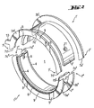
- Fig. 1 shows a first embodiment of a flange bearing half-shell 1 'in the perspective view.
- the flange bearing half shell 1 ' has a bearing shell 2 and two thrust washers 3 arranged on this bearing shell 2.
- the thrust washers 3 are welded to the outer peripheral surface of the bearing shell 2 in such a way that the thrust washers 3 are ideally perpendicular to the axis of the flange bearing or perpendicular to the axis of the bearing from the flange bearing crankshaft stand.
- the Thrust washers 3 are arranged at the edges or end faces of the bearing shell 2. Good to see is the weld 8, via which the front thrust washer 3 is connected to the bearing shell 2.
- the four ends 7 of the two thrust washers 3 extend beyond the semicircular bearing shell 2 in the circumferential direction.
- the adjacent ends 7 of the opposing thrust washers 3 each form a kind of fork. If now shown in Fig. 1 flange half bearing 1 ', which has no oil supply hole and is provided for the arrangement in the housing cover of the crankcase mounted in a housing cover arranged in the bearing cap, the ends 7 engage the thrust washers 3 in the assembled state of the crankcase in the upper housing part of the crankcase.
- the bifurcated ends 7 of the thrust washers 3 engage in the bearing saddle on which the opposite flange bearing half shell 1 "(not shown) is placed, wherein the bearing saddle or a wall belonging to the bearing saddle is fixed between the thrust washers 3.
- a flange bearing which uses the flange bearing half-shell 1 'shown in FIG. 1, accomplishes the centering of the two crankcase parts with only one, namely the flange bearing half-shell 1' shown.
- a second bearing shell which is opposite the centering flange bearing half shell 1 ', can be a bearing shell designed according to the prior art, as long as it is designed such that it can form a flange bearing together with the collar bearing half shell 1' designed according to the invention.
- thrust washers 3 form an outer surface 9, which in itself forms a sufficiently large sliding bearing surface without the addition of a further thrust washer of a second bearing shell.
- the outer surface 9 of the thrust washers 3 has two grooves 5 which intersect the outer surface 9 in the manner of a secant. These grooves 5 are required to build up a sufficiently viable lubricating film in the axial sliding bearing and to dissipate oil.
- the illustrated in Fig. 1 bundlager vomschale 1 'further has a arranged in the running surface of the bearing shell 2 groove 6.
- This groove. 6 extends in the circumferential direction, ie in the direction of the crankshaft rotation and serves as an oil reservoir for receiving lubricating oil.
- the bearing shell 2 has at its edges in the circumferential direction extending grooves 4, which increase the flexibility of the bearing shell 2 and thus the entire flange bearing half shell 1'.
- the upper flange bearing half shell 1 ' is explosively shown in the perspective view, with not on the bearing shell 2' fixed thrust washers 3a ', 3b'.
- the lower flange bearing half shell 1 "is shown in the assembled state as a finished component.
- This lower flange bearing half shell 1 is very similar to the flange bearing half shell shown in Fig. 1. Its thrust washers 3a", 3b “are arranged on the outer circumferential surface of the bearing shell and are non-detachably connected to the bearing shell 2" via a weld 8. They are in turn perpendicular to the flange bearing axis and are arranged on the front sides of the bearing shell 2 ".
- the ends 7 "of the thrust washers 3a”, 3b extendend circumferentially but only partially beyond the semicircular bearing shell Moreover, the ends 7" of these two thrust washers 3a “, 3b” assembly aids 7a ', 7b “, 7c", 7d “in the form of chamfers of the ends 7" of the thrust washers 3a “, 3b” on.
- the upper flange bearing half shell 1 ' is formed in the embodiment of the flange bearing 1 shown in FIG. 2 with the exception of two constructive elements such as the lower flange half shell 1 ".
- Another constructional element which has the upper flange half shell 1 'in contrast to the lower flange half shell 1 ", is the oil supply bore 11 arranged eccentrically in the bearing shell 2, by means of which the flange bearing 1 is supplied with lubricating oil the oil supply line in the bearing bore are aligned, so that the upper flange bearing half shell 1 'can not be mounted arbitrarily on the arranged in the upper housing part of the crankcase bearing seat.
- the ends 7 'of the thrust washers 3a', 3b 'of the upper flange bearing half shell 1' have first mounting aids 7a ', 7b', 7c ', 7d', in the mounted collar bearing 1 with the assembly aids 7a “, 7b", 7c ", 7d ", which are arranged at the ends 7" 'of the thrust washers 3a ", 3b" of the lower flange bearing half-shell 1 "in engagement.
- the assembly aids 7a ', 7b', 7c ', 7d' of the upper bearing half shell 1 ' are also formed in the form of bevels.
- the bevels on one side of the bearing shell 2 ', 2" are the same orientation, i. identical and differently oriented with respect to the bevels on the other side of this bearing shell 2 ', 2 ", i.e. different.
- the chamfers are formed in such a manner that the inner radius or the outer radius of the thrust washer 3a ', 3b', 3a “, 3b” changes continuously in the circumferential direction.
- the thrust washers 3a ', 3b', 3a “, 3b” taper towards their end 7 ', 7 ", wherein the thickness of the thrust washers 3a', 3b ', 3a", 3b "preferably remains the same.
- the thrust washers 3a ', 3b', 3a ", 3b” have in their outer surface 9 each have two grooves 5, which are required for the formation of a viable lubricating film.
- the two crankcase parts are centered on both flange bearing half shells 1 ', 1 ".
- the upper flange half shell 1' arranged in the upper housing part centers with its ends 7 'of the two stop disks 3a', 3b ', which extend at least partially in the circumferential direction over the semicircular bearing shell 2 'addition, the housing cover relative to the upper housing part of the crankcase.
Landscapes
- Engineering & Computer Science (AREA)
- General Engineering & Computer Science (AREA)
- Mechanical Engineering (AREA)
- Shafts, Cranks, Connecting Bars, And Related Bearings (AREA)
- Sliding-Contact Bearings (AREA)
- Mounting Of Bearings Or Others (AREA)
Applications Claiming Priority (3)
| Application Number | Priority Date | Filing Date | Title |
|---|---|---|---|
| DE10048256A DE10048256A1 (de) | 2000-09-29 | 2000-09-29 | Bundlager und Verfahren zu seiner Herstellung |
| PCT/DE2001/003788 WO2002029270A1 (fr) | 2000-09-29 | 2001-10-01 | Demi-coussinet de palier a collet, palier a collet pourvu d'un dispositif de centrage et plaque de butee associee |
| EP01986334A EP1320690B1 (fr) | 2000-09-29 | 2001-10-01 | Palier a collet pourvu d'un dispositif de centrage |
Related Parent Applications (1)
| Application Number | Title | Priority Date | Filing Date |
|---|---|---|---|
| EP01986334A Division EP1320690B1 (fr) | 2000-09-29 | 2001-10-01 | Palier a collet pourvu d'un dispositif de centrage |
Publications (1)
| Publication Number | Publication Date |
|---|---|
| EP1762732A1 true EP1762732A1 (fr) | 2007-03-14 |
Family
ID=61660055
Family Applications (2)
| Application Number | Title | Priority Date | Filing Date |
|---|---|---|---|
| EP01986334A Expired - Lifetime EP1320690B1 (fr) | 2000-09-29 | 2001-10-01 | Palier a collet pourvu d'un dispositif de centrage |
| EP06022371A Withdrawn EP1762732A1 (fr) | 2000-09-29 | 2001-10-01 | Palier de vilebrequin |
Family Applications Before (1)
| Application Number | Title | Priority Date | Filing Date |
|---|---|---|---|
| EP01986334A Expired - Lifetime EP1320690B1 (fr) | 2000-09-29 | 2001-10-01 | Palier a collet pourvu d'un dispositif de centrage |
Country Status (7)
| Country | Link |
|---|---|
| US (1) | US7101086B2 (fr) |
| EP (2) | EP1320690B1 (fr) |
| JP (1) | JP2004510929A (fr) |
| BR (1) | BR0114340B1 (fr) |
| DE (1) | DE50111864D1 (fr) |
| ES (1) | ES2278801T3 (fr) |
| WO (1) | WO2002029270A1 (fr) |
Cited By (1)
| Publication number | Priority date | Publication date | Assignee | Title |
|---|---|---|---|---|
| DE102016207927A1 (de) | 2016-05-09 | 2017-11-09 | Schaeffler Technologies AG & Co. KG | Stellantrieb |
Families Citing this family (24)
| Publication number | Priority date | Publication date | Assignee | Title |
|---|---|---|---|---|
| WO2002029269A1 (fr) * | 2000-09-29 | 2002-04-11 | Federal-Mogul Wiesbaden Gmbh & Co. Kg | Palier a embase soude, son procede de production et dispositif pour l'execution de ce procede |
| KR101148516B1 (ko) * | 2003-11-13 | 2012-05-21 | 페더럴-모걸 코오포레이숀 | 트러스트 와셔 및 그 제조방법 |
| EP1655473B1 (fr) * | 2004-11-08 | 2010-02-10 | Ford Global Technologies, LLC, A subsidary of Ford Motor Company | méthode pour monter un système avec arbre à cames et partie réceptrice de l'arbre à cames |
| US7354199B2 (en) * | 2005-06-01 | 2008-04-08 | Federal Mogul Worldwide, Inc. | Thrust bearing |
| DE102005030307B4 (de) * | 2005-06-23 | 2014-02-13 | Federal-Mogul Wiesbaden Gmbh & Co. Kg | Kurbelwellenhauptlager und Massenausgleichsgetriebelager |
| EP2060753B1 (fr) * | 2006-09-04 | 2012-01-25 | NTN Corporation | Roulement à rouleaux, structure de support d'arbre à cames, et moteur à combustion interne |
| GB2445952B (en) * | 2007-01-25 | 2011-07-20 | Siemens Ag | A gas turbine engine |
| JP2008247179A (ja) * | 2007-03-30 | 2008-10-16 | Aisin Seiki Co Ltd | 車両用シート装置 |
| EP2158443B1 (fr) * | 2007-06-08 | 2014-11-12 | Raytheon Company | Procédés et appareil pour adaptateur de projectile |
| DE102007055005B4 (de) | 2007-11-14 | 2009-08-27 | Federal-Mogul Wiesbaden Gmbh | Anlaufscheibe und Radial-Axial-Lager mit einer solchen |
| CN102007310B (zh) * | 2008-04-18 | 2013-04-10 | 大丰工业株式会社 | 滑动轴承 |
| KR101040754B1 (ko) | 2009-05-07 | 2011-06-14 | 오쏠라 유한회사 | 태양광 트래킹 장치용 합성수지재 베어링 |
| JP4865019B2 (ja) * | 2009-09-10 | 2012-02-01 | 大同メタル工業株式会社 | 内燃機関のコンロッド軸受 |
| US8740123B2 (en) | 2011-08-25 | 2014-06-03 | Siemens Industry, Inc. | Replaceable wear element for rolling mill laying head |
| KR101305559B1 (ko) * | 2011-11-04 | 2013-09-09 | 기아자동차주식회사 | 엔진블록의 스러스트 베어링 결합장치 |
| US8845500B2 (en) * | 2012-03-30 | 2014-09-30 | Chia-Yu Huang | Resistance adjustable rotational exerciser |
| US20150059184A1 (en) * | 2013-08-28 | 2015-03-05 | Aktiebolaget Skf | Methods of Fabricating a High Pressure Bushing and Supporting a Shaft |
| US9702411B2 (en) * | 2014-04-10 | 2017-07-11 | Roller Bearing Company Of America, Inc. | Bearing assembly with split outer ring having interference fit tabs and method of assembly of bearing |
| WO2016194423A1 (fr) * | 2015-06-03 | 2016-12-08 | 日立建機株式会社 | Engrenage réducteur |
| CN105134798A (zh) * | 2015-08-14 | 2015-12-09 | 苏州安特实业有限公司 | 一种轴套安装架 |
| CN109590665B (zh) * | 2017-07-21 | 2020-07-21 | 浙江盛达铁塔有限公司 | 双拼埋弧焊管的装配方法 |
| CN107989907A (zh) * | 2017-11-26 | 2018-05-04 | 成都宁翔机械制造有限责任公司 | 一种舰艇用防水滑动轴承 |
| DE102018220462A1 (de) * | 2018-11-28 | 2020-05-28 | Hanon Systems Efp Deutschland Gmbh | Elektrisch angetriebene Maschine, insbesondere Pumpe |
| CN118622859B (zh) * | 2024-07-01 | 2025-01-28 | 浙江中达精密部件股份有限公司 | 一种应用于风电设备的降噪式滑动轴承 |
Citations (4)
| Publication number | Priority date | Publication date | Assignee | Title |
|---|---|---|---|---|
| FR1161898A (fr) * | 1955-11-30 | 1958-09-05 | Ford | Rondelle de butée perfectionnée et palier en comportant application |
| DE2635061A1 (de) * | 1976-08-04 | 1978-02-09 | Glyco Metall Werke | Axialgleitlager |
| DE3527521A1 (de) * | 1985-07-23 | 1987-01-29 | Roland Scheufler | Bei der montage fertiggeformter axiallagerkoerper |
| DE8712192U1 (de) * | 1987-09-09 | 1987-10-15 | Glyco-Metall-Werke Daelen & Loos Gmbh, 6200 Wiesbaden | Bundlager |
Family Cites Families (6)
| Publication number | Priority date | Publication date | Assignee | Title |
|---|---|---|---|---|
| US1644611A (en) * | 1925-02-28 | 1927-10-04 | H Dux Company Inc Dr | Ball bearing |
| DE2433929A1 (de) * | 1974-07-15 | 1976-02-05 | Glyco Metall Werke | Kombiniertes radial-axial-gleitlager |
| AR211083A1 (es) | 1976-08-04 | 1977-10-14 | Glyco Metall Werke | Cojinete friccionante axial. |
| IT1175166B (it) * | 1983-02-03 | 1987-07-01 | Clevite Srl | Semicuscinetto flangiato per applicazioni motoristiche |
| GB8431132D0 (en) * | 1984-12-10 | 1985-01-16 | Ae Plc | Bearing |
| GB9127191D0 (en) * | 1991-12-21 | 1992-02-19 | T & N Technology Ltd | Flanged bearings |
-
2001
- 2001-10-01 EP EP01986334A patent/EP1320690B1/fr not_active Expired - Lifetime
- 2001-10-01 JP JP2002532814A patent/JP2004510929A/ja active Pending
- 2001-10-01 WO PCT/DE2001/003788 patent/WO2002029270A1/fr not_active Ceased
- 2001-10-01 EP EP06022371A patent/EP1762732A1/fr not_active Withdrawn
- 2001-10-01 ES ES01986334T patent/ES2278801T3/es not_active Expired - Lifetime
- 2001-10-01 BR BRPI0114340-9A patent/BR0114340B1/pt not_active IP Right Cessation
- 2001-10-01 US US10/381,712 patent/US7101086B2/en not_active Expired - Fee Related
- 2001-10-01 DE DE50111864T patent/DE50111864D1/de not_active Expired - Lifetime
Patent Citations (4)
| Publication number | Priority date | Publication date | Assignee | Title |
|---|---|---|---|---|
| FR1161898A (fr) * | 1955-11-30 | 1958-09-05 | Ford | Rondelle de butée perfectionnée et palier en comportant application |
| DE2635061A1 (de) * | 1976-08-04 | 1978-02-09 | Glyco Metall Werke | Axialgleitlager |
| DE3527521A1 (de) * | 1985-07-23 | 1987-01-29 | Roland Scheufler | Bei der montage fertiggeformter axiallagerkoerper |
| DE8712192U1 (de) * | 1987-09-09 | 1987-10-15 | Glyco-Metall-Werke Daelen & Loos Gmbh, 6200 Wiesbaden | Bundlager |
Cited By (3)
| Publication number | Priority date | Publication date | Assignee | Title |
|---|---|---|---|---|
| DE102016207927A1 (de) | 2016-05-09 | 2017-11-09 | Schaeffler Technologies AG & Co. KG | Stellantrieb |
| WO2017194046A1 (fr) | 2016-05-09 | 2017-11-16 | Schaeffler Technologies AG & Co. KG | Mécanisme de commande |
| DE102016207927B4 (de) | 2016-05-09 | 2018-07-26 | Schaeffler Technologies AG & Co. KG | Stellantrieb |
Also Published As
| Publication number | Publication date |
|---|---|
| ES2278801T3 (es) | 2007-08-16 |
| WO2002029270A1 (fr) | 2002-04-11 |
| DE50111864D1 (de) | 2007-02-22 |
| US20040136627A1 (en) | 2004-07-15 |
| EP1320690A1 (fr) | 2003-06-25 |
| US7101086B2 (en) | 2006-09-05 |
| EP1320690B1 (fr) | 2007-01-10 |
| BR0114340A (pt) | 2004-01-13 |
| BR0114340B1 (pt) | 2009-08-11 |
| JP2004510929A (ja) | 2004-04-08 |
Similar Documents
| Publication | Publication Date | Title |
|---|---|---|
| EP1320690B1 (fr) | Palier a collet pourvu d'un dispositif de centrage | |
| DE19900292C2 (de) | Universalspannvorrichtung und Verfahren zum Positionieren und Klemmen für Pleuelstangen | |
| EP3649724B1 (fr) | Procédé de réalisation d'un rotor destiné à un moteur électrique et rotor produit grâce à ce procédé | |
| DE60101537T2 (de) | Nockenmechanismus mit Kreuzrollenlager | |
| DE102009039993A1 (de) | Antriebsanordnung für ein stufenlos verstellbares Getriebe eines Kraftfahrzeuges | |
| WO2009037208A1 (fr) | Disque de démarrage et palier radial-axial doté de ce dernier | |
| EP2911826B1 (fr) | Procédé d'assemblage d'un module de moteur | |
| EP3156666B1 (fr) | Systeme de fixation d'un element de machine | |
| EP2094947A1 (fr) | Ensemble arbre à cames | |
| EP1320689B1 (fr) | Palier a embase soude, son procede de production et dispositif pour l'execution de ce procede | |
| DE69202942T2 (de) | Gebaute Welle und Verfahren zu ihrer Herstellung. | |
| DE2836395B1 (de) | Satzfraeser | |
| EP1790437B1 (fr) | Méthode pour monter en force un moyeu de roue muni d'un palier de roue | |
| WO2020083434A1 (fr) | Dispositif palier pour un turbocompresseur à gaz d'échappement et turbocompresseur à gaz d'échappement | |
| DE4137978C1 (fr) | ||
| DE3212785C3 (de) | Offenend-spinnrotor | |
| WO2001081777A1 (fr) | Unite de montage constituee d"un composant et d"au moins une vis taraudeuse | |
| WO2004009276A1 (fr) | Raccord de deux pieces de machine | |
| DE202008003936U1 (de) | Vorrichtung zum Zentrieren von Werkzeugen zur Bearbeitung von Bohrungen | |
| EP2978564A1 (fr) | Cage de serrage pourvue d'éléments de fixation | |
| AT519378B1 (de) | Lagerdeckel | |
| DE4206246C1 (en) | Device for assembly of housings with common shaft - employs offset auxiliary boss for compensation of shaft eccentricity when independently machined housings are fitted together | |
| DE102012019375A1 (de) | Werkzeug zum innenumfangsseitigen Bearbeiten wenigstens zweier Lagerstellen sowie Verfahren zum innenumfangsseitigen Bearbeiten wenigstens zweier Lagerstellen | |
| EP1538346B1 (fr) | Raccordement démontable | |
| DE102005034776B3 (de) | Verfahren zur Herstellung einer Nockenwelle |
Legal Events
| Date | Code | Title | Description |
|---|---|---|---|
| PUAI | Public reference made under article 153(3) epc to a published international application that has entered the european phase |
Free format text: ORIGINAL CODE: 0009012 |
|
| AC | Divisional application: reference to earlier application |
Ref document number: 1320690 Country of ref document: EP Kind code of ref document: P |
|
| AK | Designated contracting states |
Kind code of ref document: A1 Designated state(s): AT BE CH CY DE DK ES FI FR GB GR IE IT LI LU MC NL PT SE TR |
|
| AKX | Designation fees paid |
Designated state(s): AT BE CH CY DE DK ES FI FR GB GR IE IT LI LU MC NL PT SE TR |
|
| STAA | Information on the status of an ep patent application or granted ep patent |
Free format text: STATUS: THE APPLICATION IS DEEMED TO BE WITHDRAWN |
|
| 18D | Application deemed to be withdrawn |
Effective date: 20070917 |