EP1762736A1 - Prétention par le soufflet pour un joint coulissant - Google Patents
Prétention par le soufflet pour un joint coulissant Download PDFInfo
- Publication number
- EP1762736A1 EP1762736A1 EP05019528A EP05019528A EP1762736A1 EP 1762736 A1 EP1762736 A1 EP 1762736A1 EP 05019528 A EP05019528 A EP 05019528A EP 05019528 A EP05019528 A EP 05019528A EP 1762736 A1 EP1762736 A1 EP 1762736A1
- Authority
- EP
- European Patent Office
- Prior art keywords
- ball tracks
- joint part
- tracks
- bellows
- joint
- Prior art date
- Legal status (The legal status is an assumption and is not a legal conclusion. Google has not performed a legal analysis and makes no representation as to the accuracy of the status listed.)
- Withdrawn
Links
Images


Classifications
-
- F—MECHANICAL ENGINEERING; LIGHTING; HEATING; WEAPONS; BLASTING
- F16—ENGINEERING ELEMENTS AND UNITS; GENERAL MEASURES FOR PRODUCING AND MAINTAINING EFFECTIVE FUNCTIONING OF MACHINES OR INSTALLATIONS; THERMAL INSULATION IN GENERAL
- F16D—COUPLINGS FOR TRANSMITTING ROTATION; CLUTCHES; BRAKES
- F16D3/00—Yielding couplings, i.e. with means permitting movement between the connected parts during the drive
- F16D3/84—Shrouds, e.g. casings, covers; Sealing means specially adapted therefor
- F16D3/843—Shrouds, e.g. casings, covers; Sealing means specially adapted therefor enclosed covers
- F16D3/845—Shrouds, e.g. casings, covers; Sealing means specially adapted therefor enclosed covers allowing relative movement of joint parts due to the flexing of the cover
-
- F—MECHANICAL ENGINEERING; LIGHTING; HEATING; WEAPONS; BLASTING
- F16—ENGINEERING ELEMENTS AND UNITS; GENERAL MEASURES FOR PRODUCING AND MAINTAINING EFFECTIVE FUNCTIONING OF MACHINES OR INSTALLATIONS; THERMAL INSULATION IN GENERAL
- F16D—COUPLINGS FOR TRANSMITTING ROTATION; CLUTCHES; BRAKES
- F16D3/00—Yielding couplings, i.e. with means permitting movement between the connected parts during the drive
- F16D3/16—Universal joints in which flexibility is produced by means of pivots or sliding or rolling connecting parts
- F16D3/20—Universal joints in which flexibility is produced by means of pivots or sliding or rolling connecting parts one coupling part entering a sleeve of the other coupling part and connected thereto by sliding or rolling members
- F16D3/22—Universal joints in which flexibility is produced by means of pivots or sliding or rolling connecting parts one coupling part entering a sleeve of the other coupling part and connected thereto by sliding or rolling members the rolling members being balls, rollers, or the like, guided in grooves or sockets in both coupling parts
- F16D3/223—Universal joints in which flexibility is produced by means of pivots or sliding or rolling connecting parts one coupling part entering a sleeve of the other coupling part and connected thereto by sliding or rolling members the rolling members being balls, rollers, or the like, guided in grooves or sockets in both coupling parts the rolling members being guided in grooves in both coupling parts
- F16D3/226—Universal joints in which flexibility is produced by means of pivots or sliding or rolling connecting parts one coupling part entering a sleeve of the other coupling part and connected thereto by sliding or rolling members the rolling members being balls, rollers, or the like, guided in grooves or sockets in both coupling parts the rolling members being guided in grooves in both coupling parts the groove centre-lines in each coupling part lying on a cylinder co-axial with the respective coupling part
- F16D3/227—Universal joints in which flexibility is produced by means of pivots or sliding or rolling connecting parts one coupling part entering a sleeve of the other coupling part and connected thereto by sliding or rolling members the rolling members being balls, rollers, or the like, guided in grooves or sockets in both coupling parts the rolling members being guided in grooves in both coupling parts the groove centre-lines in each coupling part lying on a cylinder co-axial with the respective coupling part the joints being telescopic
-
- F—MECHANICAL ENGINEERING; LIGHTING; HEATING; WEAPONS; BLASTING
- F16—ENGINEERING ELEMENTS AND UNITS; GENERAL MEASURES FOR PRODUCING AND MAINTAINING EFFECTIVE FUNCTIONING OF MACHINES OR INSTALLATIONS; THERMAL INSULATION IN GENERAL
- F16D—COUPLINGS FOR TRANSMITTING ROTATION; CLUTCHES; BRAKES
- F16D3/00—Yielding couplings, i.e. with means permitting movement between the connected parts during the drive
- F16D3/16—Universal joints in which flexibility is produced by means of pivots or sliding or rolling connecting parts
- F16D3/20—Universal joints in which flexibility is produced by means of pivots or sliding or rolling connecting parts one coupling part entering a sleeve of the other coupling part and connected thereto by sliding or rolling members
- F16D3/22—Universal joints in which flexibility is produced by means of pivots or sliding or rolling connecting parts one coupling part entering a sleeve of the other coupling part and connected thereto by sliding or rolling members the rolling members being balls, rollers, or the like, guided in grooves or sockets in both coupling parts
- F16D3/223—Universal joints in which flexibility is produced by means of pivots or sliding or rolling connecting parts one coupling part entering a sleeve of the other coupling part and connected thereto by sliding or rolling members the rolling members being balls, rollers, or the like, guided in grooves or sockets in both coupling parts the rolling members being guided in grooves in both coupling parts
- F16D2003/22316—Means for fastening or attaching the bellows or gaiters
Definitions
- the invention relates to a ball-and-socket joint of the type XL sliding joint having a longitudinal axis A and having an outer joint part with a first group of axially parallel outer ball tracks and a second group of outer ball tracks crossing the longitudinal axis A at first angles ⁇ , with an inner joint part having a first A group of axially parallel inner ball tracks and a second group of inner ball tracks that intersect the longitudinal axis A at second, equal and opposite angles ⁇ , wherein outer and inner ball tracks of the first groups form first parallel track pairs that receive first balls.
- outer and inner ball tracks of the second groups form second intersecting track pairs which receive second balls
- a ball cage holding the first and second balls in circumferentially distributed cage windows in a common plane
- a shaft fixedly connected to the inner joint part
- e inem bellows for sealing the joint, which is fixedly connected at its one end at least indirectly with the outer joint part and at its other end with the shaft.
- XL-Verschegelegelenke belong due to their track design to the constant velocity sliding joints, which allow a substantial axial displacement between the outer joint part and the inner joint part. They serve to transmit torque and simultaneously compensate for changes in length in propeller shafts, especially in the side shafts of vehicle drive trains that connect a differential gear with a drive wheel, or in the longitudinal shafts of vehicle drive trains that connect a gearbox with a rear differential.
- XL-Verschegelegelenke are in versions with three first pairs of tracks and three second pairs of tracks, which alternate over the circumference, and thus have a total of six balls, as well known as in embodiments with four first pairs of tracks and four second pairs of tracks, which alternate over the circumference and thus have eight balls ( DE 38 18 730 C1 ).
- an XL constant velocity sliding joint is used in side shafts in combination with a constant velocity fixed joint, with the first differential gear side and the latter being disposed on the wheel side.
- the article extends to both joints in which the second pairs of tracks are all the same chamfered or screwed around the circumference, as well as those joints in which the second pairs of tracks over the circumference in each case in pairs are alternately bevelled or screwed in opposite directions, d.
- the ball tracks of the second group of the outer ball tracks, as well as the ball tracks of the second group of the inner ball tracks each have a pairwise alternating pitch to the longitudinal direction over the circumference.
- the invention is based on the object of switching off alternating axial movements of the joint components relative to each other.
- the solution to this consists in a ball-and-socket joint with a longitudinal axis A and with an outer joint part having a first group of axially parallel outer ball tracks and a second group of outer ball tracks crossing the longitudinal axis A at first angles ⁇ , with an inner joint part having a first group of axially parallel ones inner ball tracks and a second group of inner ball tracks that intersect the longitudinal axis A at second, equal and opposite angles ⁇ , wherein outer and inner ball tracks of the first groups form first parallel track pairs that receive first balls, and wherein outer and inner ball tracks of the second groups form second intersecting track pairs which receive second balls, a ball cage holding the first and second balls in circumferentially distributed cage windows in a common plane, a shaft fixedly connected to the inner joint part, and a bellows for sealing ng of the hinge, which is fixedly connected at one end at least indirectly to the outer joint part and at the
- the inner joint part With the based on the biasing force of the bellows axial bias between the outer joint part and the shaft, there is an equal axial preload between the outer joint part and the rotationally fixed with the shaft and axially connected to the inner joint part.
- the inner joint part is thus supported permanently on the joint balls and / or the ball cage on the outer joint part, wherein the supporting force, which is torque-independent, can be kept low, so that the advantages of low friction in the joint are largely maintained.
- the inner joint part has a defined position in the outer joint part, so that the mentioned disadvantages are suppressed in terms of vibration and noise.
- the internal biasing force in the bellows is usefully created by the fact that the bellows is installed with respect to its tension-free production length L O with shortened installation length L X , this shortening also has a stock, when the inner joint part, bridging the axial play on the balls and / or the Cage has applied to the outer joint part.
- the bellows is installed so that its largest operating length is even shorter than the stress-free production length L O.
- the bellows consists in a preferred embodiment of thermoplastic elastomer (TPE), which has a relatively high dimensional stability.
- the outer joint part may advantageously have an axially opposite to the entrance of the shaft in the outer joint part molded bottom.
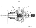
- FIG. 1 shows a sliding joint according to the invention with eight balls in a first embodiment, which is additionally illustrated in FIGS. 2 and 3.
- An outer joint part 19 with a molded-on bottom 25 and a shaft journal 26 attached thereto receives an inner joint part 20, in whose inner opening 27 a shaft 21 is inserted.
- the joint is sealed by a bellows 24, the larger collar 28 is fixed by means of a clamping band 29 on the outer joint part 19 and the smaller collar 30 is fixed by means of a clamping band 31 on the shaft 21.
- the joint is shown in a middle displacement position, from which it can be shortened or extended.
- the installation length of the bellows is marked L X.
- the bellows is under a compressive bias F FB .
- first outer ball tracks 12 can be seen, which are parallel to the longitudinal axis A of the joint, and second outer ball tracks 13, which extend at an intersection angle ⁇ 0 to the longitudinal axis A of the joint.
- the ball tracks 12 are each also axially parallel ball tracks (14) in the inner joint part 20 opposite, of which no is recognizable here;
- the ball tracks 13th are each second inner ball tracks 15 in the inner joint part 20 with respect to the longitudinal axis A form an opposite crossing angle as the tracks 13.
- first balls (16) are added, in the second track pairs 13, 15 second balls 17 are received-
- the balls 16, 17 are of a ball cage 22 which receives the balls in cage windows 23 in a common Kept level.
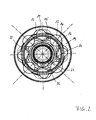
- the outer joint part 19 and the inner joint part 20 can be seen in a view of the joint with disassembled bellows and recognizable by means of a retaining ring 32 in the inner joint part shaft 21.
- the ball cage 22 is also visible.
- first outer ball tracks 12 are shown circumferentially distributed.
- first inner ball tracks 14 are provided in the inner joint part 20 .
- first pairs of ball tracks 12, 14 receive torque-transmitting balls 16.
- second outer ball tracks 13 which form a crossing angle ( ⁇ 0 ) with the longitudinal axis A.
- second outer ball tracks 13 are associated with second inner ball tracks 15 in the inner joint part 20, which have a to the tracks 13 opposite crossing angle ( ⁇ 0 ).
- the intersecting pairs of tracks 13, 15 receive second balls 17.
- the crossing angles of all four second outer ball tracks 13 ( ⁇ 0 ) and the crossing angles of all second inner ball tracks 15 ( ⁇ 0 ) are equal to one another.
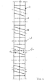
- FIG. 3 wherein a development of the inner joint part 20 shows that the four first inner ball tracks 14 are parallel to the longitudinal axis A, while the second inner ball tracks 15 form a crossing angle ⁇ 0 with respect to the longitudinal axis.
- the crossing angle ⁇ 0 is the same for all second inner ball tracks and applied in the same sense.
- the second outer ball tracks 13 associated with the second inner ball tracks 15 in the outer joint part each have an oppositely provided magnitude equal crossing angle ⁇ 0 , as already indicated in FIG.
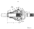
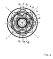
- FIG. 4 shows a sliding joint according to the invention with eight balls in a second embodiment, which is additionally illustrated in FIGS. 5 and 6.
- An outer joint part 19 with a molded-on bottom 25 and a shaft journal 26 attached thereto receives an inner joint part 20, in whose inner opening 27 a shaft 21 is inserted.
- the joint is sealed by a bellows 24, the larger collar 28 is fixed by means of a clamping band 29 on the outer joint part 19 and the smaller collar 30 is fixed by means of a clamping band 31 on the shaft 21.
- the joint is shown in a middle displacement position, from which it can be shortened or extended.
- the installation length of the bellows is marked L X.
- the bellows is under a compressive bias F FB .
- first outer ball tracks 12 can be seen, which are parallel to the longitudinal axis A of the joint, as well as two groups of second outer ball tracks 13 1 , 13 2 , which extend at an intersection angle ⁇ 1 , ⁇ 2 to the longitudinal axis A of the joint.
- the ball tracks 12 are each also axially parallel ball tracks (14) in the inner joint part 20 opposite, of which no is recognizable here;
- the ball tracks 13 1 , 13 2 are each two groups of second inner ball tracks 15 1 , 15 2 in the inner joint part 20 opposite, each with the longitudinal axis an opposite crossing angle ( ⁇ 1 , ⁇ 2 ) as the ball tracks 13 1 , 13 2 form.
- first balls (16) are added, in the two groups of second track pairs 13 1 , 15 1 , 13 2 , 15 2 are two groups of second balls 17 1 , 17 2 added.
- the balls 16, 17 1 , 17 2 are held by a ball cage 22 which receives the balls in cage windows 23 in a common plane.
- the outer joint part 19 and the inner joint part 20 can be seen in a view of the joint with disassembled bellows and recognizable by means of a retaining ring 32 in the inner joint part shaft 21.
- the ball cage 22 is also visible.
- In the outer joint part 19 are circumferentially distributed four axially parallel he ste outer ball tracks 12 shown in the inner joint part 20 of this associated axially parallel first inner ball tracks 14 are provided. In each case first pairs of ball tracks 12, 14 receive torque-transmitting balls 16.
- first outer ball tracks 12 Between each two first outer ball tracks 12 are second outer ball tracks 13 1 of a first group, which form an intersection angle ( ⁇ 1 ) with the longitudinal axis A, and second outer ball tracks 13 2 of a second group, with the longitudinal axis an oppositely offered crossing angle ( ⁇ 2 ) form.
- the second outer ball tracks 13 1 , 13 2 are associated with second inner ball tracks 15 1 , 15 2 in the inner joint part 20, each having a to the ball tracks 13 1 opposite crossing angle ( ⁇ 1 , ⁇ 2 ).
- the intersecting pairs of tracks 13 1 , 15 1 , 13 2 , 15 2 take two groups of balls 17 1 , 17 2 .
- the crossing angle of all four second outer ball tracks 13 1 , 13 2 of both groups and the crossing angle of all second inner ball tracks 15 1 , 15 2 of both groups are equal in magnitude to each other.
- FIG. 6 wherein a development of the inner joint part 20 shows that the four first inner ball tracks 14 are parallel to the longitudinal axis A, while the second inner ball tracks 15 1 of the first group form a crossing angle ⁇ 1 with respect to the longitudinal axis and the second inner ball tracks 15 2 of the second group form an opposite cross angle ⁇ 2 .
- the second inner ball tracks 15 1 , 15 2 associated second outer ball tracks 13 1 , 13 2 in the outer joint part each have an oppositely applied amount equal to the same crossing angle ⁇ 1 , ⁇ 2 as in Figure 4 already indicated.
- the bellows 24 is shown with its production-related manufacturing length L O over the waistband regions 28, 30 measured in a relaxed state, in which the bellows force-free retains its length.
- the bellows 24 is shown over the waistband areas 28, 30 measured in the shortened installation length L X , which is smaller than L O , wherein the bellows generates an axial pressure biasing force F FB .
- This causes that in the joints according to Figures 1 and 4, respectively, the inner joint part of the shaft 21 is pulled out of the outer joint part 19, toward the other or free end of the shaft 21.
- An indifferent position of the joint is hereby at least one wide range of displacement of the joint avoided. Ideally, this remains Axial preload force F FB positively maintained over the entire axial displacement range of the XL-Verschiebgelenkes. This means that even at maximum extended joint, the largest operating length of the bellows is even smaller than the tension-free production length L O.
Landscapes
- Engineering & Computer Science (AREA)
- General Engineering & Computer Science (AREA)
- Mechanical Engineering (AREA)
- Diaphragms And Bellows (AREA)
Priority Applications (1)
| Application Number | Priority Date | Filing Date | Title |
|---|---|---|---|
| EP05019528A EP1762736A1 (fr) | 2005-09-08 | 2005-09-08 | Prétention par le soufflet pour un joint coulissant |
Applications Claiming Priority (1)
| Application Number | Priority Date | Filing Date | Title |
|---|---|---|---|
| EP05019528A EP1762736A1 (fr) | 2005-09-08 | 2005-09-08 | Prétention par le soufflet pour un joint coulissant |
Publications (1)
| Publication Number | Publication Date |
|---|---|
| EP1762736A1 true EP1762736A1 (fr) | 2007-03-14 |
Family
ID=35542580
Family Applications (1)
| Application Number | Title | Priority Date | Filing Date |
|---|---|---|---|
| EP05019528A Withdrawn EP1762736A1 (fr) | 2005-09-08 | 2005-09-08 | Prétention par le soufflet pour un joint coulissant |
Country Status (1)
| Country | Link |
|---|---|
| EP (1) | EP1762736A1 (fr) |
Cited By (1)
| Publication number | Priority date | Publication date | Assignee | Title |
|---|---|---|---|---|
| WO2008141907A1 (fr) * | 2007-05-18 | 2008-11-27 | Gkn Driveline Deutschland Gmbh | Joint à rotule plongeant homocinétique avec de faibles forces plongeantes |
Citations (4)
| Publication number | Priority date | Publication date | Assignee | Title |
|---|---|---|---|---|
| US3678706A (en) * | 1969-11-20 | 1972-07-25 | Gkn Transmissions Ltd | Universal joints |
| DE3818730C1 (en) | 1988-06-01 | 1989-07-27 | Loehr & Bromkamp Gmbh, 6050 Offenbach, De | Telescopic constant-velocity joint |
| DE4435206A1 (de) * | 1993-09-30 | 1995-04-06 | Ntn Toyo Bearing Co Ltd | Kunstharz-Schutzmanschette für Gleichlaufgelenke |
| US6406375B1 (en) * | 1999-11-05 | 2002-06-18 | Gkn Walterscheid Gmbh | Protective device for a drive assembly with a double universal joint |
-
2005
- 2005-09-08 EP EP05019528A patent/EP1762736A1/fr not_active Withdrawn
Patent Citations (5)
| Publication number | Priority date | Publication date | Assignee | Title |
|---|---|---|---|---|
| US3678706A (en) * | 1969-11-20 | 1972-07-25 | Gkn Transmissions Ltd | Universal joints |
| DE3818730C1 (en) | 1988-06-01 | 1989-07-27 | Loehr & Bromkamp Gmbh, 6050 Offenbach, De | Telescopic constant-velocity joint |
| DE4435206A1 (de) * | 1993-09-30 | 1995-04-06 | Ntn Toyo Bearing Co Ltd | Kunstharz-Schutzmanschette für Gleichlaufgelenke |
| US5645286A (en) * | 1993-09-30 | 1997-07-08 | Ntn Corporation | Resin boot for constant velocity universal joints |
| US6406375B1 (en) * | 1999-11-05 | 2002-06-18 | Gkn Walterscheid Gmbh | Protective device for a drive assembly with a double universal joint |
Cited By (2)
| Publication number | Priority date | Publication date | Assignee | Title |
|---|---|---|---|---|
| WO2008141907A1 (fr) * | 2007-05-18 | 2008-11-27 | Gkn Driveline Deutschland Gmbh | Joint à rotule plongeant homocinétique avec de faibles forces plongeantes |
| US8277329B2 (en) | 2007-05-18 | 2012-10-02 | Gkn Driveline Deutschland Gmbh | Homokinetic plunging ball joint with low plunging forces |
Similar Documents
| Publication | Publication Date | Title |
|---|---|---|
| DE102007023354B4 (de) | Kugelgleichlaufverschiebegelenk mit geringen Verschiebekräften | |
| DE3730393C2 (de) | Lenkwelle für Kraftfahrzeuge, bestehend aus axial ineinander verschieblichen Wellenteilen | |
| EP2239477B1 (fr) | Joint à chemins de roulements conjugués présentant un point d'inflexion de chemin de roulement | |
| DE3126192C2 (fr) | ||
| DE112007003190B4 (de) | Gelenkanordnung mit Käfig- und Laufbahnversatz | |
| WO2008003303A1 (fr) | Unité de transmission de couple, telle qu'un joint fixe homocinétique à billes utilisé en tant que joint rzeppa et procédé de production associé | |
| DE102016113139A1 (de) | Verfahren zur Herstellung eines Käfigs für ein Kugelgleichlaufgelenk | |
| DE102009052526A1 (de) | Dämpfereinheit für eine Welle | |
| DE102012214556A1 (de) | Freilaufeinrichtung | |
| EP2483572A1 (fr) | Joint coulissant | |
| DE102009057914A1 (de) | Schwingungsdämpfer für einen Antriebsstrang | |
| DE102008011914A1 (de) | Vorspanneinheit | |
| DE102013211407A1 (de) | Torsionsschwingungsdämpfer mit Bogenfeder und Endkappe | |
| EP1685332B1 (fr) | Joint a billes a pistes croisees, pourvu de pistes de roulement obliques | |
| DE19915417A1 (de) | Tripodegelenk mit elastischen Mitteln | |
| DE102006058860A1 (de) | Gleichlauffestgelenk | |
| EP2076683B1 (fr) | Joint homocinétique coulissant | |
| WO2008071281A1 (fr) | Amortisseur de vibrations de torsion pourvu de patins d'extrémité et ensemble transmission comprenant un tel amortisseur de vibrations de torsion | |
| DE102007048328B4 (de) | Gleichlauffestgelenk | |
| DE102012110276A1 (de) | Leichtbaugelenk für die Übertragung von Drehbewegungen | |
| DE2336121A1 (de) | Elastische kupplung fuer kraftuebertragung mit hoher anfangsflexibilitaet, insbesondere fuer kupplungsscheiben | |
| DE102005029042A1 (de) | Gleichlauffestgelenk | |
| DE102017114940A1 (de) | Rampenaktor sowie Kupplungseinrichtung mit Rampenaktor | |
| DE102007027767A1 (de) | Verschiebelagerung | |
| DE102009013082A1 (de) | Schwingungsdämpfer für einen Antriebsstrang |
Legal Events
| Date | Code | Title | Description |
|---|---|---|---|
| PUAI | Public reference made under article 153(3) epc to a published international application that has entered the european phase |
Free format text: ORIGINAL CODE: 0009012 |
|
| AK | Designated contracting states |
Kind code of ref document: A1 Designated state(s): AT BE BG CH CY CZ DE DK EE ES FI FR GB GR HU IE IS IT LI LT LU LV MC NL PL PT RO SE SI SK TR |
|
| AX | Request for extension of the european patent |
Extension state: AL BA HR MK YU |
|
| 17P | Request for examination filed |
Effective date: 20070817 |
|
| 17Q | First examination report despatched |
Effective date: 20070925 |
|
| AKX | Designation fees paid |
Designated state(s): DE |
|
| STAA | Information on the status of an ep patent application or granted ep patent |
Free format text: STATUS: THE APPLICATION HAS BEEN WITHDRAWN |
|
| 18W | Application withdrawn |
Effective date: 20071119 |