EP1762876A1 - Système à lentille de zoom, dispositif d"imagerie, et caméra - Google Patents
Système à lentille de zoom, dispositif d"imagerie, et caméra Download PDFInfo
- Publication number
- EP1762876A1 EP1762876A1 EP05753306A EP05753306A EP1762876A1 EP 1762876 A1 EP1762876 A1 EP 1762876A1 EP 05753306 A EP05753306 A EP 05753306A EP 05753306 A EP05753306 A EP 05753306A EP 1762876 A1 EP1762876 A1 EP 1762876A1
- Authority
- EP
- European Patent Office
- Prior art keywords
- lens
- lens unit
- lens system
- object side
- lens element
- Prior art date
- Legal status (The legal status is an assumption and is not a legal conclusion. Google has not performed a legal analysis and makes no representation as to the accuracy of the status listed.)
- Withdrawn
Links
Images


Classifications
-
- G—PHYSICS
- G02—OPTICS
- G02B—OPTICAL ELEMENTS, SYSTEMS OR APPARATUS
- G02B15/00—Optical objectives with means for varying the magnification
- G02B15/14—Optical objectives with means for varying the magnification by axial movement of one or more lenses or groups of lenses relative to the image plane for continuously varying the equivalent focal length of the objective
- G02B15/143—Optical objectives with means for varying the magnification by axial movement of one or more lenses or groups of lenses relative to the image plane for continuously varying the equivalent focal length of the objective having three groups only
- G02B15/1435—Optical objectives with means for varying the magnification by axial movement of one or more lenses or groups of lenses relative to the image plane for continuously varying the equivalent focal length of the objective having three groups only the first group being negative
- G02B15/143507—Optical objectives with means for varying the magnification by axial movement of one or more lenses or groups of lenses relative to the image plane for continuously varying the equivalent focal length of the objective having three groups only the first group being negative arranged -++
Definitions
- the present invention relates to a zoom lens system, an imaging device and a camera, and in particular to: a zoom lens system of high image quality and small size which is stable to a digital still camera, a digital video camera and the like; an imaging device including the zoom lens system; and a camera including the imaging device.
- a lens system having a comparatively long back focus is necessary in order that a member such as an optical low-pass filter should be arranged between the rearmost part of the lens element and the solid-state image sensor.
- a satisfactory telecentric property is required in order to avoid shading that could cause a reduction in the amount of light in the periphery on the image surface.
- a large number of types of digital still cameras can be considered.
- One of these types is a compact type.
- zoom lens systems suitable for digital still cameras of compact type in the prior art, three-unit zoom lens systems have been proposed that, in order from the object side, comprise a first lens unit having negative optical power, a second lens unit having positive optical power and a third lens unit having positive optical power.
- the inventors of the present application have proposed a three-unit zoom lens system appropriate for a digital still camera of compact type (Patent Document 1).
- Patent Document 1 International Publication No. 03/085440 Pamphlet
- An object of the present invention is to provide: a zoom lens system having a short entire length during shooting and non-shooting and a high resolution; and an imaging device using the zoom lens system. Further, an object of the present invention is to provide a camera including the imaging device.
- a zoom lens system that forms an optical image of an object with a variable magnification, in order from the object side, comprises a first lens unit of negative optical power, a second lens unit of positive optical power and a third lens unit of positive optical power, wherein the lens units move respectively along an optical axis so that a magnification is changed with changing a distance between the respective lens units
- the first lens unit in order from the object side, comprises a first lens element having a negative meniscus shape with the surface of strong curvature facing the image side and a second lens element which is a positive lens element with the surface of strong curvature facing the object side
- the second lens unit comprises at least three lens elements including an object side lens element of the second lens unit which is a positive lens element arranged on the most object side with the surface of strong curvature facing the object side and an image side lens element of the second lens unit which is a positive lens element arranged on the most image side with the convex surface facing the object side
- the third lens unit comprises at least three lens elements including an object side lens
- the second lens unit in order from the object side, comprises a third lens element which is a positive lens element with the surface of strong curvature facing the object side, a fourth lens element which is a positive lens element, a fifth lens element which is a negative lens element, and a sixth lens element which is a positive lens element with the convex surface facing the object side.
- the second lens unit in order from the object side, comprises a third lens element which is a positive lens element with the surface of strong curvature facing the object side, a fourth lens element which is a negative lens element, and a fifth lens element which is a positive lens element with the convex surface facing the object side.
- the following condition is satisfied; 0.01 ⁇ r RR + r RF / ( r RR - r RF ) ⁇ 0.3 where,
- the second lens unit moves in a direction perpendicular to the optical axis so that image blur generated by vibration of the zoom lens system can be compensated, and the following condition is satisfied; 1.7 ⁇ 1 - m G ⁇ 2 ⁇ T ⁇ m G ⁇ 3 ⁇ T ⁇ 2.1 where,
- An imaging device capable of converting an optical image of a photographic object into an electric image signal and then outputting the signal comprises:
- a camera capable of shooting a photographic object and then outputting it as an electric image signal comprises:
- the present invention can provide: a zoom lens system having a short entire length during shooting and non-shooting and a high resolution; and an imaging device using the zoom lens system. Further, the present invention can provide a camera including the imaging device.
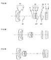
- FIGS. 1A to 1C are construction diagrams of a zoom lens system according to Embodiment 1.
- FIGS. 3A to 3C are construction diagrams of a zoom lens system according to Embodiment 2.
- FIGS. 5A to 5C are construction diagrams of a zoom lens system according to Embodiment 3.
- FIGS. 7A to 7C are construction diagrams of a zoom lens system according to Embodiment 4.
- FIGS. 9A to 9C are construction diagrams of a zoom lens system according to Embodiment 5.
- Each figure shows a zoom lens system in an infinity in-focus condition.
- FIGS. 1A, 3A, 5A, 7A and 9A show the lens construction at a wide-angle limit (the shortest focal length condition: focal length f w ).
- FIGS. 1C, 3C, 5C, 7C and 9C show the lens construction at a telephoto limit (the longest focal length condition: focal length f T ).
- Each zoom lens system according to Embodiments 1 to 5 in order from the object side, comprises a first lens unit G1 of negative optical power, a diaphragm A, a second lens unit G2 of positive optical power and a third lens unit G3 of positive optical power.
- the first lens unit moves with locus of a convex to the image side, while the second lens unit and the diaphragm monotonically move to the object side, and while the third lens unit moves with locus of a convex or a concave to the image side.
- the straight line described on the leftmost side in the figure indicates the position of the image surface S.
- a plane parallel plate P such as an optical low-pass filter or a face plate of an image sensor is provided.
- these lens units are arranged in a desired power construction so that size reduction is achieved in the entire lens system in a state that the optical performance is maintained.
- the first lens unit G1 in order from the object side, comprises a first lens element L1 having a negative meniscus shape with the surface of strong curvature facing the image side and a second lens element L2 which is a positive lens element with the surface of strong curvature facing the object side.
- the second lens unit G2 comprises at least three lens elements including an object side lens element of the second lens unit which is a positive lens element arranged on the most object side with the surface of strong curvature facing the object side, and an image side lens element of the second lens unit which is a positive lens element arranged on the most image side with the convex surface facing the object side. Since the zoom lens system according to Embodiments 1 to 5 has the above construction, an optical system is realized in which each lens unit is constructed from a small number of lens elements and which can compactly be accommodated during non-use.
- the second lens unit G2 in order from the object side, comprises: a third lens element L3 (the most object side lens element of the second lens unit) which is a positive lens element with the surface of strong curvature facing the object side; a fourth lens element L4 which is a positive lens element, a fifth lens element L5 which is a negative lens element; and a sixth lens element L6 (the most image side lens element of the second lens unit) which is a positive lens element with the convex surface facing the object side.
- a third lens element L3 the most object side lens element of the second lens unit
- a fourth lens element L4 which is a positive lens element
- a fifth lens element L5 which is a negative lens element
- a sixth lens element L6 the most image side lens element of the second lens unit
- the zoom lens system according to Embodiments 1 to 4 when the second lens unit G2 is constructed as described above, aberration can sufficiently be compensated.
- the most image side lens element of the second lens unit is constructed from a positive lens element with the convex surface facing the object side, the entire length of the second lens unit G2 can be reduced.
- the second lens unit G2 in order from the object side, comprises a third lens element L3 which is a positive lens element with the surface of strong curvature facing the object side, a fourth lens element L4 which is a negative lens element, and a fifth lens element L5 which is a positive lens element with the convex surface facing the object side.
- the zoom lens system according to Embodiment 5 when the second lens unit G2 is constructed as described above, aberration can sufficiently be compensated.
- the most image side lens element of the second lens unit is constructed from a positive lens element with the convex surface facing the object side, the entire length of the second lens unit G2 can be reduced.
- the number of lenses that constitute the second lens unit G2 can be reduced. This reduces the causes of occurrence of decentering aberration during assembling, and hence realizes a zoom lens system which can easily be assembled and adjusted.
- the third lens unit G3 comprises solely one bi-convex positive lens element (a seventh lens element L7 in Embodiments 1 to 4 and a sixth lens element L6 in Embodiment 5).
- the zoom lens system of each embodiment has the above construction, and thereby realizes size reduction during retraction. Further, in the zoom lens system of each embodiment, the third lens unit G3 moves along the optical axis so that focusing is performed from an infinity in-focus condition to a close object in-focus condition.
- Conditions are described below that are to be satisfied by the zoom lens system according to each embodiment.
- a plurality of conditions are set forth that are to be satisfied by the zoom lens system according to each embodiment. Then, the construction of a zoom lens system that satisfies all the conditions is most desirable. However, when an individual condition is satisfied, a zoom lens system can be obtained that achieves the corresponding effect.
- the condition (1) is a condition for reducing the maximum value of the entire optical length during use and for ensuring satisfactory imaging characteristics.
- the maximum value of the entire optical length during use is to be reduced, it is ideal that the entire optical length at a wide-angle limit is made equal to the entire optical length at a telephoto limit. Nevertheless, if the entire optical length at a wide-angle limit were intended to be made strictly equal to the entire optical length at a telephoto limit, imaging characteristics could be degraded in some cases.
- the condition (1) is a condition obtained in consideration of this situation. When the condition (1) is not satisfied, it becomes difficult to shorten the entire optical length during use and ensure satisfactory imaging characteristics.
- the condition (2) is a condition for shortening the entire optical length during use as much as possible and for compensating the occurrence of various aberrations with satisfactory balance.
- the value of the condition equation exceeds the upper limit, the object-image distance of the second lens unit G2 becomes long so that the entire optical length during use becomes long.
- the entire optical length becomes short.
- the power of the third lens unit G3 becomes large so that curvature of field generated in the third lens unit G3 becomes under.
- the curvature of field becomes difficult to be compensated by the first lens unit G1 and the second lens unit G2.
- the condition (3) is a condition for reducing the tilt angle of the principal ray that is incident on the solid-state image sensor at the maximum image height, that is, achieving satisfactory telecentric property, and for reducing curvature of field.
- the value of the condition equation goes below the lower limit, although the telecentric property becomes satisfactory, curvature of field of the entire lens system cannot be compensated.
- the value of the condition equation exceeds the upper limit, although the curvature of field is reduced, the telecentric property becomes insufficient.
- the condition (4) is a condition for compensating, with satisfactory balance, various aberrations generated in the second lens unit G2 and for shortening the entire optical length of the entire lens system during use.
- the value of the condition equation exceeds the upper limit, the deviation of the object side principal point of the second lens unit G2 toward the object side is insufficient.
- the interval from the image side principal point of the first lens unit G1 to the object side principal point of the second lens unit G2 at a telephoto limit were made to be a desired length, a space used for arranging a diaphragm between the first lens unit G1 and the second lens unit G2 would become impossible to be ensured.
- the condition (5) is also a condition for compensating, with satisfactory balance, various aberrations generated in the second lens unit G2 and for shortening the entire optical length of the entire lens system during use.
- the value of the condition equation goes below the lower limit, the deviation of the object side principal point of the second lens unit G2 toward the object side is insufficient.
- the interval from the image side principal point of the first lens unit G1 to the object side principal point of the second lens unit G2 at a telephoto limit were made to be a desired length, a space used for arranging a diaphragm between the first lens unit G1 and the second lens unit G2 would become impossible to be ensured.
- the condition (6) is a condition for restricting the radius of curvature of the object side surface of the first lens element L1 and thereby reducing the negative distortion at a wide-angle limit.
- the value of the condition equation goes below the lower limit, the negative distortion at a wide-angle limit becomes small. Nevertheless, the coma aberration and the astigmatism become excessive. Thus, the imaging characteristics in the periphery part of the shot image cannot be made satisfactory.
- the value of the condition equation exceeds the upper limit, the negative distortion at a wide-angle limit cannot be reduced by the subsequent lens surfaces.
- the condition (7) is a condition for restricting the radius of curvature of the image side surface of the second lens element L2 and thereby reducing the negative distortion at a wide-angle limit.
- the value of the condition equation goes below the lower limit, the absolute value of distortion at a wide-angle limit becomes small. Nevertheless, the coma aberration and the astigmatism become excessive. Thus, the imaging characteristics in the periphery part of the shot image cannot be made satisfactory.
- the value of the condition equation exceeds the upper limit, the negative distortion at a wide-angle limit cannot be reduced by the subsequent lens surfaces.
- the condition (8) is a condition for achieving balance between the entire length and the aberration compensation of the second lens unit G2.
- the value of the condition equation goes below the lower limit, the spherical aberration and the coma aberration generated in the lens unit G2 become difficult to be compensated with satisfactory balance by other lenses.
- the value of the condition equation exceeds the upper limit, the axial surface distance between the most image side lens element of the second lens unit and the lens surface which is adjacent to the most image side lens element on the object side becomes large.
- the entire optical length during use and the entire length during non-use cannot be shortened.
- the condition (9) is also a condition for achieving balance between the entire length and the aberration compensation of the second lens unit G2.
- the value of the condition equation goes below the lower limit, the spherical aberration and the coma aberration generated in the lens unit G2 become difficult to be compensated with satisfactory balance by other lenses.
- the value of the condition equation exceeds the upper limit, the axial surface distance between the most image side lens element of the second lens unit and the lens surface which is adjacent to the most image side lens element on the object side becomes large.
- the entire optical length during use and the entire length during non-use cannot be shortened.
- the condition (10) is also a condition for achieving balance between the entire length and the aberration compensation of the second lens unit G2.
- the value of the condition equation goes below the lower limit, the spherical aberration and the coma aberration generated in the lens unit G2 become difficult to be compensated with satisfactory balance by other lenses.
- the value of the condition equation exceeds the upper limit, the axial surface distance between the most image side lens element of the second lens unit and the lens surface which is adjacent to the most image side lens element on the object side becomes large.
- the entire optical length during use and the entire length during non-use cannot be shortened.
- the condition (11) is also a condition for achieving balance between the entire length and the aberration compensation of the second lens unit G2 .
- the value of the condition equation goes below the lower limit, the spherical aberration and the coma aberration generated in the lens unit G2 become difficult to be compensated with satisfactory balance by other lenses.
- the value of the condition equation exceeds the upper limit, the axial surface distance between the most image side lens element of the second lens unit and the lens surface which is adjacent to the most image side lens element on the object side becomes large. Thus, the entire optical length during use and the entire length during non-use cannot be shortened.
- the condition (12) is also a condition for achieving balance between the entire length and the aberration compensation of the second lens unit G2.
- the value of the condition equation goes below the lower limit, the spherical aberration and the coma aberration generated in the lens unit G2 become difficult to be compensated with satisfactory balance by other lenses.
- the value of the condition equation exceeds the upper limit, the axial surface distance between the most image side lens element of the second lens unit and the lens surface which is adjacent to the most image side lens element on the object side becomes large.
- the entire optical length during use and the entire length during non-use cannot be shortened.
- the condition (13) is also a condition for achieving balance between the entire length and the aberration compensation of the second lens unit G2.
- the value of the condition equation goes below the lower limit, the spherical aberration and the coma aberration generated in the lens unit G2 become difficult to be compensated with satisfactory balance by other lenses.
- the value of the condition equation exceeds the upper limit, the axial surface distance between the most image side lens element of the second lens unit and the lens surface which is adjacent to the most image side lens element on the object side becomes large. Thus, the entire optical length during use and the entire length during non-use cannot be shortened.
- the second lens unit moves in a direction perpendicular to the optical axis so that image blur generated by vibration of the zoom lens system can be compensated, and that the following condition (14) is satisfied; 1.7 ⁇ 1 - m G ⁇ 2 ⁇ T ⁇ m G ⁇ 3 ⁇ T ⁇ 2.1 where,
- the condition (14) is a condition equation for achieving satisfactory imaging characteristics during image blur compensation.
- the value of the condition equation goes below the lower limit, decentering of the second lens unit G2 necessary for causing decentering in the image by a predetermined amount becomes excessive.
- fluctuation in the aberration caused by the parallel movement of the second lens unit G2 becomes large so that the imaging characteristics in the image periphery part is degraded.
- the value of the condition equation exceeds the upper limit, decentering of the second lens unit G2 necessary for causing decentering in the image by a predetermined amount becomes extremely small.
- processes for parallel movement of the second lens unit G2 with high accuracy becomes difficult to be performed.
- pixel deviation during shooting cannot be reduced sufficiently.
- satisfactory imaging characteristics become difficult to be achieved during image blur compensation.
- the range of the condition (14) may be set forth as follows. Then, the above effect is achieved more successfully.
- each lens unit is composed exclusively of refractive type lenses that deflect the incident light by refraction (that is, lenses of a type in which deflection is achieved at the interface between media each having a distinct refractive index).
- each lens unit may be constructed from diffractive type lenses that deflect the incident light by diffraction; refractive-diffractive hybrid type lenses that deflect the incident light by a combination of diffraction and refraction; or gradient index type lenses that deflect the incident light by distribution of refractive index in the medium.
- a reflecting surface may be arranged in the optical path so that the optical path may be bent before or after the zoom lens system or alternatively in the middle.
- the bending position may be set up arbitrarily depending on the necessity. When the optical path is bent appropriately, thickness reduction in appearance can be achieved in a camera.
- a construction has been given in which a plate is arranged that includes an optical low-pass filter arranged between the final surface of the zoom lens system and the image sensor.
- This low-pass filter may be: a birefringent type low-pass filter made of, for example, a crystal whose predetermined crystal orientation is adjusted; or a phase type low-pass filter that achieves required characteristics of optical cut-off frequency by diffraction effect.
- the low-pass filter may be omitted depending on the characteristics of the solid-state image sensor for receiving the optical image in the zoom lens system.
- FIG. 16 is a sectional construction diagram of a digital still camera according to Embodiment 6.
- the digital still camera comprises: an imaging device including a zoom lens system 1 and a solid-state image sensor 2 that is a CCD; a liquid crystal display monitor 3; a body 4; and the like.
- the employed zoom lens system 1 is the zoom lens system according to Embodiment 1.
- the zoom lens system 1 comprises a first lens unit G1, a second lens unit G2, a diaphragm A and a third lens unit G3.
- the zoom lens system 1 is arranged on the front side, while the solid-state image sensor 2 that is a CCD is arranged on the rear side of the zoom lens system 1.
- the liquid crystal display monitor 3 is arranged on the rear side of the body 4.
- An optical image of a photographic object acquired through the zoom lens system 1 is formed in the image surface S.
- the solid-state image sensor 2 has a recording pixel number of horizontal 2304 ⁇ vertical 1728 (approximately 4 million pixels), a pixel pitch of horizontal 2.5 ⁇ m ⁇ vertical 2.5 ⁇ m, and a recording screen size of horizontal 5.76 mm X vertical 4.32 mm (diagonal 7.2 mm). Each pixel has a microscopic positive lens.
- a lens barrel comprises a main barrel 5, a moving barrel 6, and a cylindrical cam 7.
- the first lens unit G1, the second lens unit G2, and the third lens unit G3 move to predetermined positions relative to the solid-state image sensor 2, so that magnification can be changed ranging from the wide-angle limit to the telephoto limit.
- the third lens unit frame G3 can be moved in the optical axis direction by a motor for focus adjustment.
- a digital still camera when the zoom lens system of Embodiment 1 is used in the digital still camera, a digital still camera can be provided that has a zoom ratio of approximately 3, a view angle of 65° or the like at a wide-angle limit, a high resolution, and a thin depth-directional size during non-use.
- any one of the zoom lens systems of Examples 2 to 5 may be used in place of the zoom lens system of Example 1.
- the optical system of the digital still camera shown in FIG. 16 may be used in a digital video camera for moving images. In this case, moving images with high resolution can be acquired in addition to still images.
- An imaging device comprising a zoom lens system of Embodiments 1 to 5 described above and an image sensor such as a CCD or a CMOS may be applied to a mobile telephone, a PDA (Personal Digital Assistance), a surveillance camera in a surveillance system, a Web camera, a vehicle-mounted camera or the like.
- a PDA Personal Digital Assistance
- a surveillance camera in a surveillance system a surveillance system
- a Web camera a vehicle-mounted camera or the like.
- an image blur compensation function when an image blur compensation function is to be installed in the digital still camera described above, a mechanism for moving the second lens unit G2 in a direction perpendicular to the optical axis and an image blur compensation motor or the like may be added, and then the image blur compensation motor may be controlled by an image blur compensation signal.
- the image blur compensation signal may be generated by a publicly known method such as a method of generating from the vibration detection result of the digital still camera detected by a publicly known angular rate sensor or a method of generating by image processing from the image signal formed in the solid-state image sensor.
- a digital zoom function may be installed in which the image formed in the center part of the solid-state image sensor is enlarged to the entire screen by a signal processing circuit.
- the digital zoom function is used, the effect by the blur compensation function is remarkably obtained as described below.
- the degree of blur unclearness in a case that the zoom lens is inclined by image blur can be evaluated by using the ratio (image decentering ratio) of the amount of image decentering to the diagonal length of the solid-state image sensor.
- This ratio is constant regardless of the size of printing the signal of the shot image.
- the diagonal length of the shot image in a case that the digital zoom function is not used is equal to the diagonal length of the effective area of the solid-state image sensor.
- the diagonal length of the shot image in a case that the digital zoom function is used becomes smaller than the diagonal length of the solid-state image sensor.
- the image blur compensation function When the image blur compensation function is used, the amount of image decentering becomes remarkably small. Thus, even when the digital zoom function is used, the image decentering ratio becomes small so that image blur unclearness is improved remarkably.
- any one of the zoom lens systems of Embodiments 2 to 5 may be used in place of the zoom lens system of Embodiment 1.
- a solid-state image sensor may be used that has a recording pixel number of horizontal 2560 ⁇ vertical 1920 (approximately 5 million pixels), a pixel pitch of horizontal 2.2 ⁇ m ⁇ vertical 2.2 ⁇ m, and a recording screen size of horizontal 5.632 mm ⁇ vertical 4.224 mm (diagonal 7.04 mm).
- the construction of the digital still camera shown in FIG. 16 may be used in a video camera for moving images.
- still images with high resolution can be acquired in addition to moving images.
- ⁇ is the conic constant
- D, E, F, G, H, I and J are the fourth-order, sixth-order, eighth-order, tenth-order, twelfth-order, fourteenth-order and sixteenth-order aspherical coefficients, respectively.
- a zoom lens system of Example 1 corresponds to that of Embodiment 1 shown in FIGS. 1A to 1C.
- Table 1 shows the lens data of the zoom lens system of Example 1.
- Table 2 shows the aspherical data.
- Table 3 shows the focal length, the F-number, the view angle, the entire optical length and the variable axial distance data, when the shooting distance is ⁇ .
- a zoom lens system of Example 2 corresponds to that of Embodiment 2 shown in FIGS. 3A to 3C.
- Table 4 shows the lens data of the zoom lens system of Example 2.
- Table 5 shows the aspherical data.
- Table 6 shows the focal length, the F-number, the view angle, the entire optical length and the variable axial distance data, when the shooting distance is ⁇ .
- a zoom lens system of Example 3 corresponds to that of Embodiment 3 shown in FIGS. 5A to 5C.
- Table 7 shows the lens data of the zoom lens system of Example 3.
- Table 8 shows the aspherical data.
- Table 9 shows the focal length, the F-number, the view angle, the entire optical length and the variable axial distance data, when the shooting distance is ⁇ .
- a zoom lens system of Example 4 corresponds to that of Embodiment 4 shown in FIGS. 7A to 7C.
- Table 10 shows the lens data of the zoom lens system of Example 4.
- Table 11 shows the aspherical data.
- Table 12 shows the focal length, the F-number, the view angle, the entire optical length and the variable axial distance data, when the shooting distance is ⁇ .
- a zoom lens system of Example 5 corresponds to that of Embodiment 5 shown in FIGS. 9A to 9C.
- Table 13 shows the lens data of the zoom lens system of Example 5.
- Table 14 shows the aspherical data.
- Table 15 shows the focal length, the F-number, the view angle, the entire optical length and the variable axial distance data, when the shooting distance is ⁇ .
- Table 16 shows values corresponding to the condition equations in Examples 1 to 5.
- Table 16 Example 1 Example 2 Example 3 Example 4 Example 5
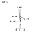
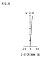
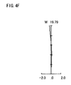
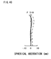
- FIGS. 2A to 2I are longitudinal aberration diagrams of a zoom lens system according to Example 1.
- FIGS. 4A to 4I are longitudinal aberration diagrams of a zoom lens system according to Example 2.
- FIGS. 6A to 6I are longitudinal aberration diagrams of a zoom lens system according to Example 3.
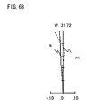
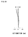
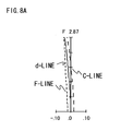
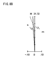
- FIGS. 8A to 8I are longitudinal aberration diagrams of a zoom lens system according to Example 4.
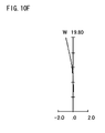
- FIGS. 10A to 10I are longitudinal aberration diagrams of a zoom lens system according to Example 5.
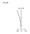
- FIGS. 2A to 2C, 4A to 4C, 6A to 6C, 8A to 8C, and 10A to 10C show the aberration at the wide-angle limit.
- FIGS. 2D to 2F, 4D to 4F, 6D to 6F, 8D to 8F, and 10D to 10F show the aberration at the middle position.
- FIGS. 2G to 2I, 4G to 4I, 6G to 6I, 8G to 8I, and 10G to 10I show the aberration at the telephoto limit.
- FIGS. 2A, 2D, 2G, 4A, 4D, 4G, 6A, 6D, 6G, 8A, 8D, 8G, 10A, 10D and 10G show the spherical aberration.
- FIGS. 2C, 2F, 2I, 4C, 4F, 4I, 6C, 6F, 6I, 8C, 8F, 8I, 10C, 10F and 10I show the distortion.
- the vertical axis indicates the F-number.
- the solid line, the short dash line and the long dash line indicate the characteristics to the d-line, the F-line and the C-line, respectively.
- the vertical axis indicates the half view angle.
- the solid line and the dash line indicate the characteristics to the sagittal image plane and the meridional image plane, respectively.
- the vertical axis indicates the half view angle.
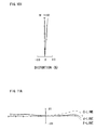
- FIGS. 11A to 11F are lateral aberration diagrams of a zoom lens system according to Example 1 at a telephoto limit.
- FIGS. 12A to 12F are lateral aberration diagrams of a zoom lens system according to Example 2 at a telephoto limit.
- FIGS. 13A to 13F are lateral aberration diagrams of a zoom lens system according to Example 3 at a telephoto limit.
- FIGS. 14A to 14F are lateral aberration diagrams of a zoom lens system according to Example 4 at a telephoto limit.
- FIGS. 15A to 15F are lateral aberration diagrams of a zoom lens system according to Example 5 at a telephoto limit.
- FIGS. 11A to 11C, 12A to 12C, 13A to 13C, 14A to 14C, and 15A to 15C are lateral aberration diagrams at a telephoto limit corresponding to a basic state that image blur compensation is not performed.
- FIGS. 11D to 11F, 12D to 12F, 13D to 13F, 14D to 14F, and 15D to 15F are lateral aberration diagrams corresponding to an image blur compensation state at a telephoto limit in which the entire second lens unit G2 is moved by a predetermined amount in a direction perpendicular to the optical axis.
- FIGS. 11A to 11C, 12A to 12C, 13A to 13C, 14A to 14C, and 15A to 15C are lateral aberration diagrams at a telephoto limit corresponding to a basic state that image blur compensation is not performed.
- FIGS. 11D to 11F, 12D to 12F, 13D to 13F, 14D to 14F, and 15D to 15F are lateral aber
- FIGS. 11A, 12A, 13A, 14A and 15A correspond to the lateral aberration at an image point at 75% of the maximum image height.
- FIGS. 11B, 12B, 13B, 14B and 15B correspond to the lateral aberration at the axial image point.
- FIGS. 11C, 12C, 13C, 14C and 15C correspond to the lateral aberration at an image point at -75% of the maximum image height.
- FIGS. 11D, 12D, 13D, 14D and 15D correspond to the lateral aberration at an image point at 75% of the maximum image height.
- FIGS. 11E, 12E, 13E, 14E and 15E correspond to the lateral aberration at the axial image point.
- FIGS. 11F, 12F, 13F, 14F and 15F correspond to the lateral aberration at an image point at -75% of the maximum image height.
- the meridional image plane is adopted as the plane containing the optical axis of the first lens unit G1 and the optical axis of the second lens unit G2.
- the amount of movement of the second lens unit G2 in a direction perpendicular to the optical axis in the image blur compensation state is 0.094 mm in Example 1,0.094 mm in Example 2, 0.095 mm in Example 3, 0.094 mm in Example 4, and 0.098 mm in Example 5.
- the amount of image decentering in a case that the zoom lens system inclines by 0.6° when the shooting distance is ⁇ at a telephoto limit is equal to the amount of image decentering in a case that the entire second lens unit G2 moves in parallel in a direction perpendicular to the optical axis by each of the above values.
- the zoom lens system according to the present invention is applicable to a digital input device such as a digital still camera, a digital video camera, a mobile telephone, a PDA (Personal Digital Assistance), a surveillance camera in a surveillance system, a Web camera or a vehicle-mounted camera.
- a digital input device such as a digital still camera, a digital video camera, a mobile telephone, a PDA (Personal Digital Assistance), a surveillance camera in a surveillance system, a Web camera or a vehicle-mounted camera.
- the present zoom lens system is suitable for a shooting optical system such as a digital still camera or a digital video camera requiring high image quality.
Landscapes
- Physics & Mathematics (AREA)
- General Physics & Mathematics (AREA)
- Optics & Photonics (AREA)
- Lenses (AREA)
Applications Claiming Priority (2)
| Application Number | Priority Date | Filing Date | Title |
|---|---|---|---|
| JP2004191992 | 2004-06-29 | ||
| PCT/JP2005/011761 WO2006001431A1 (fr) | 2004-06-29 | 2005-06-27 | Système à lentille de zoom, dispositif d’imagerie, et caméra |
Publications (1)
| Publication Number | Publication Date |
|---|---|
| EP1762876A1 true EP1762876A1 (fr) | 2007-03-14 |
Family
ID=35781862
Family Applications (1)
| Application Number | Title | Priority Date | Filing Date |
|---|---|---|---|
| EP05753306A Withdrawn EP1762876A1 (fr) | 2004-06-29 | 2005-06-27 | Système à lentille de zoom, dispositif d"imagerie, et caméra |
Country Status (5)
| Country | Link |
|---|---|
| US (2) | US7369323B2 (fr) |
| EP (1) | EP1762876A1 (fr) |
| JP (1) | JP4792395B2 (fr) |
| CN (2) | CN1977205A (fr) |
| WO (1) | WO2006001431A1 (fr) |
Families Citing this family (15)
| Publication number | Priority date | Publication date | Assignee | Title |
|---|---|---|---|---|
| EP1762876A1 (fr) * | 2004-06-29 | 2007-03-14 | Matsushita Electric Industrial Co., Ltd. | Système à lentille de zoom, dispositif d"imagerie, et caméra |
| US7471453B2 (en) * | 2005-11-17 | 2008-12-30 | Panasonic Corporation | Zoom lens system, imaging device and camera |
| JP4923764B2 (ja) * | 2006-06-12 | 2012-04-25 | 株式会社ニコン | ズームレンズとこれを有する光学装置 |
| JP2008164724A (ja) | 2006-12-27 | 2008-07-17 | Sony Corp | ズームレンズ及び撮像装置 |
| JP4928288B2 (ja) * | 2007-01-30 | 2012-05-09 | キヤノン株式会社 | ズームレンズ及びそれを有する撮像装置 |
| US7755847B2 (en) | 2007-05-29 | 2010-07-13 | Panasonic Corporation | Zoom lens system, imaging device and camera |
| US7593166B2 (en) * | 2007-05-29 | 2009-09-22 | Panasonic Corporation | Zoom lens system, imaging device and camera |
| JP5309553B2 (ja) * | 2007-12-25 | 2013-10-09 | 株式会社ニコン | ズームレンズ、及び、このズームレンズを備えた光学機器 |
| JP5349938B2 (ja) * | 2008-12-11 | 2013-11-20 | キヤノン株式会社 | ズームレンズ |
| JP2010256417A (ja) * | 2009-04-21 | 2010-11-11 | Sony Corp | ズームレンズ及び撮像装置 |
| US8749892B2 (en) | 2011-06-17 | 2014-06-10 | DigitalOptics Corporation Europe Limited | Auto-focus actuator for field curvature correction of zoom lenses |
| JP5284456B2 (ja) * | 2011-12-28 | 2013-09-11 | キヤノン株式会社 | ズームレンズ及びそれを有する撮像装置 |
| WO2016017724A1 (fr) * | 2014-07-30 | 2016-02-04 | 株式会社ニコン | Système optique à puissance variable, dispositif optique, et procédé de fabrication d'un système optique à puissance variable |
| DE102020129622B4 (de) * | 2020-11-10 | 2023-11-02 | Leica Camera Aktiengesellschaft | Objektiv fester Brennweite |
| CN114185161B (zh) * | 2021-12-13 | 2023-09-05 | 江西晶超光学有限公司 | 光学系统、镜头模组和电子设备 |
Family Cites Families (46)
| Publication number | Priority date | Publication date | Assignee | Title |
|---|---|---|---|---|
| US6308011B1 (en) * | 1998-03-31 | 2001-10-23 | Canon Kabushiki Kaisha | Zoom lens and photographic apparatus having the same |
| JP3706787B2 (ja) * | 2000-04-14 | 2005-10-19 | キヤノン株式会社 | ズームレンズ及びそれを用いた光学機器 |
| JP3619117B2 (ja) | 2000-04-14 | 2005-02-09 | キヤノン株式会社 | ズームレンズ及びそれを用いた光学機器 |
| JP3710352B2 (ja) | 2000-03-27 | 2005-10-26 | キヤノン株式会社 | ズームレンズ及びそれを用いた光学機器 |
| US6545819B1 (en) * | 1999-08-31 | 2003-04-08 | Canon Kabushiki Kaisha | Zoom lens and optical apparatus having the same |
| JP2001281545A (ja) | 1999-10-06 | 2001-10-10 | Canon Inc | ズームレンズ及びそれを用いた光学機器 |
| US6498687B1 (en) * | 1999-10-06 | 2002-12-24 | Canon Kabushiki Kaisha | Zoom lens and optical apparatus having the same |
| JP4460734B2 (ja) | 2000-05-23 | 2010-05-12 | オリンパス株式会社 | 電子撮像装置 |
| JP4483086B2 (ja) * | 2000-12-25 | 2010-06-16 | コニカミノルタホールディングス株式会社 | ズームレンズ |
| JP3548537B2 (ja) * | 2001-02-22 | 2004-07-28 | キヤノン株式会社 | ズームレンズ及びそれを用いた光学機器 |
| US6671103B2 (en) * | 2000-12-27 | 2003-12-30 | Canon Kabushiki Kaisha | Zoom lens and optical apparatus using the same |
| US6828218B2 (en) | 2001-05-31 | 2004-12-07 | Samsung Electronics Co., Ltd. | Method of forming a thin film using atomic layer deposition |
| US6664358B2 (en) | 2001-06-28 | 2003-12-16 | Nova Chemicals (International) S.A. | Highly alternating ethylene styrene interpolymers |
| JP2003036650A (ja) * | 2001-07-23 | 2003-02-07 | Sony Corp | ディスク記録再生装置 |
| JP2003057547A (ja) * | 2001-08-14 | 2003-02-26 | Canon Inc | ズームレンズ及びそれを有する光学機器 |
| JP2003159553A (ja) | 2001-09-17 | 2003-06-03 | Tokyo Electron Ltd | 塗布膜形成装置 |
| JP4076332B2 (ja) * | 2001-10-04 | 2008-04-16 | オリンパス株式会社 | 電子撮像装置 |
| JP4039838B2 (ja) * | 2001-10-11 | 2008-01-30 | オリンパス株式会社 | 電子撮像装置 |
| JP4039837B2 (ja) * | 2001-10-11 | 2008-01-30 | オリンパス株式会社 | 電子撮像装置 |
| JP4046499B2 (ja) * | 2001-10-18 | 2008-02-13 | オリンパス株式会社 | ズームレンズ及びそれを用いた電子撮像装置 |
| JP4043753B2 (ja) | 2001-10-22 | 2008-02-06 | オリンパス株式会社 | 電子撮像装置 |
| JP2003140047A (ja) | 2001-10-30 | 2003-05-14 | Canon Inc | ズームレンズ及びそれを有する光学機器 |
| JP2003128261A (ja) * | 2001-10-30 | 2003-05-08 | Heishin Engineering & Equipment Co Ltd | 一軸偏心ねじポンプを備えた脱水ケーキ用フィーダ |
| JP4112210B2 (ja) * | 2001-11-07 | 2008-07-02 | オリンパス株式会社 | ズームレンズ及びそれを用いた電子撮像装置 |
| JP3706827B2 (ja) * | 2001-11-09 | 2005-10-19 | キヤノン株式会社 | ズームレンズ及びそれを有する光学機器 |
| JP4097931B2 (ja) * | 2001-11-16 | 2008-06-11 | オリンパス株式会社 | ズームレンズ及びそれを用いた電子撮像装置 |
| JP4294299B2 (ja) | 2001-11-26 | 2009-07-08 | オリンパス株式会社 | ズームレンズ及びそれを用いた電子撮像装置 |
| US7002755B2 (en) * | 2001-11-26 | 2006-02-21 | Olympus Corporation | Zoom lens, and electronic imaging system using the same |
| JP3943922B2 (ja) | 2001-12-11 | 2007-07-11 | オリンパス株式会社 | 撮像装置 |
| JP4138671B2 (ja) * | 2002-04-11 | 2008-08-27 | 松下電器産業株式会社 | ズームレンズ及びそれを用いた電子スチルカメラ |
| JP2003329512A (ja) * | 2002-05-10 | 2003-11-19 | Koyo Seiko Co Ltd | 転がり軸受の固有振動周波数の測定装置及び測定方法 |
| US20040007641A1 (en) | 2002-07-10 | 2004-01-15 | Dickie Robert G. | Hose reeler with sprinkler head |
| JP3830867B2 (ja) * | 2002-07-10 | 2006-10-11 | Necエレクトロニクス株式会社 | シングルチップマイクロコンピュータおよびそのブート領域切り替え方法 |
| JP2004083260A (ja) * | 2002-08-28 | 2004-03-18 | Akira Sugimoto | 生活支援具移動装置 |
| JP4503918B2 (ja) * | 2002-11-20 | 2010-07-14 | オリンパス株式会社 | 撮像装置 |
| JP2004246141A (ja) * | 2003-02-14 | 2004-09-02 | Olympus Corp | 電子撮像装置 |
| JP2004318105A (ja) * | 2003-03-31 | 2004-11-11 | Konica Minolta Photo Imaging Inc | ズームレンズ装置 |
| JP4366109B2 (ja) * | 2003-05-06 | 2009-11-18 | キヤノン株式会社 | ズームレンズ及びそれを有する光学機器 |
| US7075732B2 (en) * | 2003-09-22 | 2006-07-11 | Olympus Corporation | Zoom optical system, and imaging system incorporating the same |
| JP4489398B2 (ja) | 2003-09-22 | 2010-06-23 | オリンパス株式会社 | ズームレンズ及びそれを用いた電子撮像装置 |
| JP2005164653A (ja) * | 2003-11-28 | 2005-06-23 | Kyocera Corp | 撮像装置 |
| JP4378188B2 (ja) * | 2004-02-23 | 2009-12-02 | キヤノン株式会社 | ズームレンズ及びそれを有する撮像装置 |
| US7092170B2 (en) * | 2004-04-30 | 2006-08-15 | Olympus Corporation | Zoom lens and image pickup apparatus |
| EP1762876A1 (fr) * | 2004-06-29 | 2007-03-14 | Matsushita Electric Industrial Co., Ltd. | Système à lentille de zoom, dispositif d"imagerie, et caméra |
| JP4612823B2 (ja) * | 2004-09-16 | 2011-01-12 | キヤノン株式会社 | ズームレンズ及びそれを有する撮像装置 |
| JP4914136B2 (ja) * | 2005-09-06 | 2012-04-11 | キヤノン株式会社 | ズームレンズ及びそれを有する撮像装置 |
-
2005
- 2005-06-27 EP EP05753306A patent/EP1762876A1/fr not_active Withdrawn
- 2005-06-27 CN CNA2005800218848A patent/CN1977205A/zh active Pending
- 2005-06-27 US US11/631,003 patent/US7369323B2/en not_active Expired - Fee Related
- 2005-06-27 CN CN2009101385176A patent/CN101539660B/zh not_active Expired - Fee Related
- 2005-06-27 JP JP2006528675A patent/JP4792395B2/ja not_active Expired - Fee Related
- 2005-06-27 WO PCT/JP2005/011761 patent/WO2006001431A1/fr not_active Ceased
-
2008
- 2008-03-03 US US12/073,192 patent/US7697215B2/en not_active Expired - Fee Related
Non-Patent Citations (1)
| Title |
|---|
| See references of WO2006001431A1 * |
Also Published As
| Publication number | Publication date |
|---|---|
| US7697215B2 (en) | 2010-04-13 |
| CN1977205A (zh) | 2007-06-06 |
| JP4792395B2 (ja) | 2011-10-12 |
| CN101539660A (zh) | 2009-09-23 |
| US7369323B2 (en) | 2008-05-06 |
| CN101539660B (zh) | 2013-07-03 |
| JPWO2006001431A1 (ja) | 2008-04-17 |
| US20080158691A1 (en) | 2008-07-03 |
| US20070285801A1 (en) | 2007-12-13 |
| WO2006001431A1 (fr) | 2006-01-05 |
Similar Documents
| Publication | Publication Date | Title |
|---|---|---|
| US7697215B2 (en) | Zoom lens system, imaging device and camera | |
| US7751125B2 (en) | Zoom lens, imaging device, and camera having imaging device | |
| EP2657744B1 (fr) | Système d'objectif à focale variable, dispositif à objectif interchangeable, et système d'appareil photographique | |
| US8427756B2 (en) | Zoom lens system, imaging device and camera | |
| US8339501B2 (en) | Zoom lens system, imaging device and camera | |
| US8446520B2 (en) | Zoom lens system, imaging device and camera | |
| EP1655635A2 (fr) | Objectif, dispositif d'imagerie et caméra | |
| US20120154524A1 (en) | Zoom Lens System, Imaging Device and Camera | |
| US7212349B2 (en) | Zoom lens system | |
| EP2075614A2 (fr) | Objectif à focale variable | |
| US7236308B2 (en) | Zoom lens system, imaging device, and camera | |
| JP5042643B2 (ja) | ズームレンズ系、撮像装置及びカメラ | |
| US9182575B2 (en) | Zoom lens system, imaging device and camera | |
| US7755847B2 (en) | Zoom lens system, imaging device and camera | |
| US20110102640A1 (en) | Zoom lens system, imaging device and camera | |
| US8395848B2 (en) | Zoom lens system, imaging device and camera | |
| US8537268B2 (en) | Zoom lens system, imaging device and camera | |
| US20100177217A1 (en) | Zoom lens system, imaging device and camera | |
| US8432618B2 (en) | Zoom lens system, imaging device and camera | |
| EP1921482A1 (fr) | Zoom optique compact de type rétrofocus ayant deux groupes de lentilles |
Legal Events
| Date | Code | Title | Description |
|---|---|---|---|
| PUAI | Public reference made under article 153(3) epc to a published international application that has entered the european phase |
Free format text: ORIGINAL CODE: 0009012 |
|
| 17P | Request for examination filed |
Effective date: 20070125 |
|
| RBV | Designated contracting states (corrected) |
Designated state(s): DE FR GB |
|
| DAX | Request for extension of the european patent (deleted) | ||
| RBV | Designated contracting states (corrected) |
Designated state(s): DE FR GB |
|
| STAA | Information on the status of an ep patent application or granted ep patent |
Free format text: STATUS: THE APPLICATION HAS BEEN WITHDRAWN |
|
| 18W | Application withdrawn |
Effective date: 20071109 |