EP1763025A1 - Vorrichtung und Datenträgerkassette - Google Patents
Vorrichtung und Datenträgerkassette Download PDFInfo
- Publication number
- EP1763025A1 EP1763025A1 EP06254772A EP06254772A EP1763025A1 EP 1763025 A1 EP1763025 A1 EP 1763025A1 EP 06254772 A EP06254772 A EP 06254772A EP 06254772 A EP06254772 A EP 06254772A EP 1763025 A1 EP1763025 A1 EP 1763025A1
- Authority
- EP
- European Patent Office
- Prior art keywords
- disk
- generating line
- center
- optical disk
- stabilizing member
- Prior art date
- Legal status (The legal status is an assumption and is not a legal conclusion. Google has not performed a legal analysis and makes no representation as to the accuracy of the status listed.)
- Granted
Links
Images







Classifications
-
- G—PHYSICS
- G11—INFORMATION STORAGE
- G11B—INFORMATION STORAGE BASED ON RELATIVE MOVEMENT BETWEEN RECORD CARRIER AND TRANSDUCER
- G11B17/00—Guiding record carriers not specifically of filamentary or web form, or of supports therefor
- G11B17/02—Details
- G11B17/022—Positioning or locking of single discs
- G11B17/028—Positioning or locking of single discs of discs rotating during transducing operation
-
- G—PHYSICS
- G11—INFORMATION STORAGE
- G11B—INFORMATION STORAGE BASED ON RELATIVE MOVEMENT BETWEEN RECORD CARRIER AND TRANSDUCER
- G11B17/00—Guiding record carriers not specifically of filamentary or web form, or of supports therefor
- G11B17/32—Maintaining desired spacing between record carrier and head, e.g. by fluid-dynamic spacing
Definitions
- the present invention generally relates to disk apparatuses and disk cartridges, and more particularly a disk apparatus configured to conduct recording and/or reproducing information onto/from a disk, and a disk cartridge configured to accommodate the disk.
- Optical disks that store mass digitized data in response to, for example, the recent digitization of television broadcasting are in demand.
- a basic method of improving recording density on the optical disks may be to reduce the diameter of a beam spot used for recording/reproducing information onto/from the optical disk.
- the wavelength of light As for the wavelength of light, the red light wavelength of approximately 650 nm is used on a DVD (digital versatile disk) while the near infrared light wavelength of approximately 780 nm is used on a CD (compact disk). Recently, a semiconductor laser of blue-violet light has been developed and it is expected that a laser light of approximately 400 nm will be used.
- the objective lens for a CD has less than 0.5 NA while the objective lens for a DVD has approximately 0.6 NA.
- the numerical aperture (NA) must be enlarged further in the future.
- NA of the objective lens and shortening the wavelength of light may result in making the depth of focus of an optical system including the objective lens smaller. Because of this, it will be necessary to increase focus servo accuracy of the optical disk apparatus. Moreover, when the objective lens having a larger NA is used, the distance between the objective lens and a recording surface of the optical disk becomes shorter. Thus, surface vibration of the optical disk should be reduced or a pickup problem of a crash between the objective lens and the optical disk may occur just before the focus servo is activated.
- a disk apparatus disclosed in Japanese Patent Application Publication No. 57-33619 has a stabilizing member called a back plate formed by bending both ends of a circular plate.
- the back plate is pushed toward a recording surface of the disk so that surface vibration in the vicinity of a head is suppressed.
- a peculiar flexing operation is required of the optical disk, following a bending part defined by a plane surface forming a recess surface. Hence, such a peculiar flexing operation may not follow due to high speed of rotation.
- a disk apparatus disclosed in " Optical Readout of Videodisc", IEEE Transaction on Consumer Electronics, November, 1976, pp. 304-308 has a stabilizing board called a saddle plate and a stabilizing member called a U-shaped stabilizer.
- the disk When information is recorded or reproduced onto or from the disk, the disk is rotated so that the disk is clamped in a gap of the U-shaped stabilizer.
- a negative pressure is generated by using the saddle plate.
- the disk is curved in a direction opposite to that of the disk apparatus disclosed in Japanese Patent Application Publication No. 57-33619 so that the surface vibration is selectively stabilized in a specific area in the gap.
- the negative pressure generated by the saddle plate may not be able to resist a centrifugal force applied to the disk so that the disk may not have a desirable curved configuration and the surface vibration in the specific area in the gap may increase.
- Japanese Patent Application Publication No. 57-33619 describes that a stabilizing member having a curved surface (hereinafter "continuous surface") which is evenly curved is not proper for stabilizing a flexible optical disk medium.
- continuous surface a stabilizing member having a curved surface which is evenly curved is not proper for stabilizing a flexible optical disk medium.
- inventors of the present invention studied and found that this continuous surface effectively acts in stabilizing the flexible disk in an area where the rotational speeds exceeds 4000 rpm.
- the inventors of the present invention realized that, in a stabilizing member having a simple continuous surface, (i) in a case where the continuous surface is cylindrically curved concave shaped against a disk, as compared to a surface vibration property in the vicinity of a generating line passing a center of the continuous surface, a surface vibration property at its downstream side in a rotational direction is more stable; and (ii) in a case where the continuous surface is convex shaped against a disk, as compared to a surface vibration property in the vicinity of a generating line passing a center of the continuous surface, a surface vibration property at its downstream side in a rotational direction is more stable.
- embodiments of the present invention may provide a novel and useful disk apparatus and disk cartridge in which the above-mentioned problems are eliminated.
- the embodiments of the present invention may provide a disk apparatus whereby at least one of reproducing precision and recording precision of information from and onto a flexible disk can be improved.
- the embodiments of the present invention may also provide a disk cartridge whereby access precision of a head for at least one of reproducing precision and recording precision of information from and onto a flexible disk can be improved.
- One aspect of the present invention may be to provide a disk apparatus, including a head configured to move along a recording surface of a rotating disk; and a stabilizing member provided so as to face the disk; wherein a facing surface of the stabilizing member facing the disk includes a curved surface whose symmetrical axis is a center generating line passing through a center of the facing surface; and the head reciprocally moves along a path which is offset from the center generating line.
- the surface vibration of the disk is suppressed by the facing surface of the stabilizing member when the information is reproduced or recorded from or onto the disk that is rotated.
- the head of the disk apparatus moves along a path where the surface vibration is suppressed most effectively, namely the path that is offset from the generating line (hereinafter "center generating line") passing through the center of the facing surface.
- the precision of the head accessing the disk of the head is improved so that at least one of reproducing precision and recording precision of information from and onto the disk can be improved.
- a disk apparatus including a head configured to move along a recording surface of a rotating disk; and a stabilizing member provided so as to face the disk; wherein a facing surface of the stabilizing member facing the disk includes a cylindrically curved concave surface whose symmetrical axis is a center generating line passing through a center of the facing surface; and an area including the center generating line is a flat surface.
- the surface vibration of the disk is suppressed by the facing surface of the stabilizing member when the information is reproduced or recorded from or onto the disk that is rotated. Therefore, the precision of the head accessing the disk is improved so that at least one of reproducing precision and recording precision of information from and onto the disk can be improved.
- a disk cartridge including: a casing configured to rotatably accommodate a flexible disk; and a stabilizing member provided so as to face the disk; wherein a facing surface of the stabilizing member facing the disk includes a curved surface whose symmetrical axis is a center generating line passing through a center of the facing surface; and a slot is formed in a position that is offset from the center generating line in the casing; and the slot defines a moving path of a head, the head configured to perform at least one of recording and reproducing information onto and from a recording surface of the disk.
- the surface vibration of the disk is suppressed by the facing surface of the stabilizing member when the information is reproduced or recorded from or onto the disk that is rotated.
- the head of the disk apparatus moves along a path where the surface vibration is suppressed most effectively, namely the path that is offset from the center generating line.
- the precision of the head accessing the disk is improved so that at least one of reproducing precision and recording precision of information from and onto the disk can be improved.
- a disk cartridge including a casing configured to rotatably accommodate a flexible disk; and a stabilizing member provided so as to face a recording surface of the disk; wherein a facing surface of the stabilizing member facing the disk includes a cylindrically curved concave surface whose symmetrical axis is a center generating line passing through a center of the facing surface; and an area including the center generating line is a flat surface.
- the surface vibration of the disk is suppressed by the facing surface of the stabilizing member when the information is reproduced or recorded from or onto the disk that is rotated. Therefore, the precision of the head accessing the disk is improved so that at least one of reproducing precision and recording precision of information from and onto the disk can be improved.
- FIG. 1 through FIG. 18 A description of the present invention is now given, with reference to FIG. 1 through FIG. 18, including embodiments of the present invention.
- FIG. 1 is a view of a schematic structure of a disk apparatus 100 of a first embodiment of the present invention.
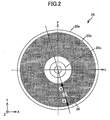
- FIG. 2 is a view for explaining an optical disk 20 shown in FIG. 1.
- FIG. 3 is a plan view of a stabilizing member 30 shown in FIG. 1.
- FIG. 4 is a view for explaining a measurement position of the optical disk 20 in a stabilizing experiment on the disk apparatus 100.
- FIG. 5 is a view for explaining surface vibration of the optical disk 20 when the stabilizing member 30 is used.
- a disk apparatus 100 is an optical disk apparatus whereby information can be recorded and reproduced onto and from a flexible optical disk 20.
- the disk apparatus 100 includes a motor 22, a spindle shaft 24, a pick-up 26, a stabilizing member 30, a housing 10, and a control device (not shown in FIG. 1).
- the motor 22 has a rotational shaft 22a provided in parallel with a Z axis.
- the spindle shaft 24 is fixed to a +Z end of the rotational shaft 22a of the motor 22.
- the pick-up 26 operates at least one of recording and reproducing information onto and from the optical disk 29.
- the stabilizing member 30 stabilizes rotation of the optical disk 20.
- the housing 10 receives the above-mentioned parts.
- the control device not shown in FIG. 1 controls the pick-up 26 and the motor 22.
- a flexible optical disk made of a circular plate polycarbonate sheet having a center where a round hole is formed, a diameter of 120 mm, and a thickness of 100 ⁇ m is used as the optical disk 20.
- a recording layer is deposited on an area 20b shown in gray in FIG. 2 at -Z side of the sheet 20a.
- the area 20b is from an inside diameter of 50 mm to an outside diameter 116 mm.
- the recording layer is formed by a process discussed below. Heat is transferred to the area 20b of the sheet 20a so as to form a stamper with grooves having a pitch of 0.6 ⁇ m and width of 0.3 ⁇ m. Then, an Ag reflective layer having thickness of approximately 120 nm, a (ZrO 2 -Y 2 O 3 )-SiO 2 layer having thickness of approximately 7 nm, an AgInSbTeGe layer having thickness of approximately 10 nm, a ZnS-SiO 2 layer having thickness of approximately 25 nm, and an Si 3 N 4 layer having thickness of approximately 10 nm are deposited in order by sputtering.
- an UV resin is spin-coated and cured by illumination with an ultraviolet light. Then, a transparent protective film having thickness of approximately 10 ⁇ m is formed in order to protect the recording layer and the disk substrate.
- a circular plate 20c having an external diameter of approximately 30 mm, an internal diameter of approximately 15 mm, and thickness of approximately 0.3 mm is provided in the center of the optical disk 20 so that the center of the circular plate 20c is coincident with the center of the sheet 20a.
- an xy coordinate system with the center of the optical disk 20 as the origin is defined.
- the stabilizing member 30 is, for example, a circular cylinder member having a low height, an external diameter of approximately 125 mm, and a circular shape opening situated in the center and having a diameter of approximately 32 mm.
- a +Z surface of the stabilizing member 30 is fixed to a ceiling surface.
- a -Z surface of the stabilizing member 30 is a curved surface (hereinafter "acting surface") facing the optical disk 20 and has a cylindrically curved concave shaped configuration.
- the acting surface of the stabilizing member 30 has a generating line (hereinafter “center generating line L") passing through the center of the acting surface and being parallel with Y axis.
- the acting surface of the stabilizing member 30 is curved at, for example, a curvature radius of approximately 1000 mm.
- a flat part, an area shaded gray in FIG. 3 is defined by two straight lines parallel with the Y axis and separated from the center generating line in -x and +x directions at a distance S (approximately 17.5 mm in this case) and an external circumference of the acting surface.
- the spindle shaft 24 is a circular cylinder shaped member having a step. More specifically, the spindle shaft 24 has a circular cylinder shaped large diameter part and a small diameter part provided on an upper end of the large diameter part. The small diameter part of the spindle shaft 24 is inserted into the round hole of the circular plate 20c and the optical disk 20 is supported from a lower side by an upper surface of the large diameter part, so that the optical disk 20 is attached to the spindle shaft 24 in a state where the recording layer is a lower surface and the center of the optical disk 20 is coincident with the center of the acting surface.
- the optical disk 20 may be attached to the spindle shaft 24 so that a distance between a surface opposite to the recording surface on the assumption that the optical disk 20 is flat and the flat part of the acting surface of the stabilizing member 30 is approximately 150 ⁇ m.
- the motor 22 By driving the rotational shaft 22a, the motor 22 rotates the optical disk 20 via the spindle shaft 24 in a range of, for example, approximately 4000 through 20000 rpm.
- the rotational speed of the optical disk 20 is controlled by a control device (not shown).
- the pick-up 26 is arranged at a lower side (-z side) of the optical disk 20 and includes an optical system including a light source or objective lens and a light receiving element.
- the pick-up 26 directs a laser light onto a recording surface of the optical disk 20 rotated by the motor 22 and receives a reflection light from the recording surface. As a result of this, information is read (reproduced) from the optical disk 20 and written (recorded) onto the optical disk 20. As shown by arrows a and a' in FIG. 2, the pick-up 26 is driven along a straight line passing through the center of the optical disk 20 at an angle of approximately 10 degrees with the y axis, by a pick-up driving device (not shown). Under this structure, the pick-up 26 moves along a straight line passing through the center of the acting surface of the stabilizing member 30 at an angle of approximately 10 degrees with the center generating line L.
- the stabilizing member 30 causes the optical disk 20 to generate an aerodynamic force so as to balance the force of restitution generated for the optical disk 20 and the repulsive force.
- surface vibration of the optical disk 20, that is vibration in a direction of a rotational axis of the optical disk 20 can be reduced.
- the inventors of the present invention conducted a stabilizing experiment using the above-discussed stabilizing member 30.
- the stabilizing experiment as shown in FIG. 4, in a state where the optical disk 20 is rotated in a direction shown by an arrow b, amplitudes in z axis directions generated due to the surface vibration of the optical disk 20 at positions on a circumference having an included center angle 100 degrees are measured.
- the circumference of the positions having the included center angle 100 degrees is defined by a point P1 at the -Y side of an external circumference of the optical disk 20, and points P0 and P3 situated at -50 degrees and +50 degrees from the point P1.
- a force F is applied to the optical disk 20 in a direction so as to separate the optical disk 20 from the stabilizing member 30.
- An area where the optical disk 20 is close to the stabilizing member 30 exists at a downstream side of the force F.
- an area where the optical disk 20 is close to the stabilizing member 30 exists in the vicinity of the point P1 at an upstream side in a rotational direction of the optical disk 20.
- the surface vibration of the optical disk 20 at a part where the optical disk 20 and the stabilizing member 30 are close is effectively suppressed. More specifically, a tangential profile of surface vibration in respective positions on the circumference defined by the points P0 through P3 is shown in FIG. 5(B).
- the stabilizing member 30 shown in FIG. 3 having a flat part provided in the vicinity of the center generating line and a curved surface elsewhere is used, as seen in a disk circumferential direction, there are two parts where the surface vibration is effectively suppressed. Considering symmetrical positions at 180 degrees on the opposite side, there are four such parts in the entire surface of the stabilizing member 30. This phenomenon was confirmed in the vicinity of 4000 rpm as the rotational speed of the optical disk 20. When the rotational speed of the optical disk 20 exceeded 10000 rpm, this phenomenon was remarkable.
- a table 1 included below shows a result of measurement of vibration amplitude ( ⁇ m) of the optical disk 20 at several points, P4, P5, P6, P7, P8, P9, P10, P11, and P12, by using a laser displacement gage in a state where the rotational speed of the optical disk 20 is changed from 4000 rpm to 14000 rpm in 2000 rpm steps.
- the point P4 is situated at approximately 25 mm from the center of the optical disk 20 in the -Y direction.
- the point P5 is situated at approximately 40 mm from the center of the optical disk 20 in the -Y direction.
- the point P6 is situated at approximately 58 mm from the center of the optical disk 20 in the -Y direction.
- the point P7 and the point P10 are situated at approximately 25 mm from the center of the optical disk 20 on two straight lines connecting the center of the optical disk 20 and the point P2 and point P2', respectively.
- the point P8 and the point P11 are situated at approximately 40 mm from the center of the optical disk 20 on two straight lines connecting the center of the optical disk 20 and the point P2 and point P2', respectively.
- the point P9 and the point P12 are situated at approximately 58 mm from the center of the optical disk 20 on two straight lines connecting the center of the optical disk 20 and the point P2 and point P2', respectively.
- the vibration amplitudes at points P4, P5, P7, P8, P9, P10, P11, and P12 are equal to or less than approximately 10 ⁇ m; and the vibration amplitude at the point P6 drastically exceed 15 ⁇ m.
- a table 2 included below shows a result of measurement of tilt angles in a circumferential direction of the optical disk 20 at several points, P4, P5, P6, P7, P8, P9, P10, P11, and P12, by using a laser autocollimator in a state where the rotational speed of the optical disk 20 is changed from 4000 rpm to 14000 rpm in 2000 rpm steps.
- the tilt angles at the points P4, P5, P6, P7, P8, and P9 are approximately 0 degree ( ⁇ within 0.1 degree).
- Tilt angle of the disk surface in the disk circumferential direction (deg) The number of rotation (rpm) P4 P5 P6 P7 P8 P9 P10 P11 P12 4000 0.00 0.04 0.06 0.00 0.02 0.04 0.20 0.50 1.00 6000 0.00 0.04 0.06 0.00 0.02 0.04 0.20 0.50 1.00 8000 0.00 0.04 0.06 0.00 0.02 0.04 0.20 0.50 1.00 10000 0.00 0.04 0.06 0.00 0.02 0.04 0.20 0.50 1.00 12000 0.00 0.04 0.06 0.00 0.02 0.04 0.20 0.50 1.00 14000 0.00 0.04 0.06 0.00 0.02 0.04 0.20 0.50 1.00
- first path a moving path of the pick-up 26 along the straight line defined by the points P7, P8, and P9
- second path a moving path of the pick-up 26 along the straight line defined by the points P10, P11, and P12
- the vibration amplitude of the optical disk 20 being equal to or less than approximately 10 ⁇ m and therefore the access precision can be improved.
- the first path as compared to the second path, as shown in the table 2, the tilt angle of the optical disk 20 in the vicinity of the path is small.
- the pick-up 26 moves above the first path wherein the effect of improving the access precision is highest.
- the tilt angle is close to 0 (zero) degrees. Therefore, for example, by making the recording density of the optical disk 20 low or making the range of an information recording area of the external circumferential part of the optical disk 20 narrow, the straight line defined by the points P4, P5, and P6 can be sufficiently used as the moving path of the pick-up 26.
- the tilt angle of the pick-up 26 with the disk surface is controlled so as to be close to 0 (zero) by providing a mechanism for controlling the tilt angle of the pick-up 26 and following a change of the tilt angle of the disk surface scanning by the pick-up 26.
- the moving path of the pick-up 26 is set along a position where there is little influence due to the surface vibration generated in the optical disk 20 when the information is reproduced or recorded and the tilt angle is small (the tilt angle is close to 0 (zero)).
- the pick-up 26 may move along a straight line (defined by the points P10, P11 and P12) at an angle of approximately -40 degrees with the y axis because of reasons discussed above. Even in this case, suppressed small surface vibration lightens the load of the pick-up 26 and the precision of the access to the optical disk 20 can be improved. As a result of this, at least one of reproducing precision and recording precision of information from and onto the optical disk 20 can be improved.
- the pick-up 26 moves, as shown in FIG. 2, along the straight line at an angle of approximately 10 degrees with the y axis in the first embodiment of the present invention
- the present invention is not limited to this.
- the pick-up 26 may move along a straight line that is parallel with the y axis and separated from the Y axis at, for example, approximately 10 mm to an upstream side (+x side) in a rotational direction.
- a table 3 included below shows a result of measurement of vibration amplitude ( ⁇ m) of the optical disk 20 at several points, P7', P8', and P9' by using a laser displacement gage in a state where the rotational speed of the optical disk 20 is changed from 4000 rpm to 14000 rpm in 2000 rpm steps.
- the point P7' is situated at approximately 25 mm from the center of the optical disk 20 on the moving path of the optical disk 20.
- the point P8' is situated at approximately 40 mm from the center of the optical disk 20 on the moving path of the optical disk 20.
- the point P9' is situated at approximately 58 mm from the center of the optical disk 20 on the moving path of the optical disk 20.
- a table 4 included below shows a result of measurement of tilt angles at several points, P7', P8', and P9', by using a laser autocollimator in a state where the rotational speed of the optical disk 20 is changed from 4000 rpm to 14000 rpm in 2000 rpm steps.
- the amplitudes (surface vibrations) at the points P7', P8', and P9' are equal to or less than approximately 10 ⁇ m.
- the tilt angles at the points P7', P8', and P9' are approximately 0 degree ( ⁇ within 0.1 degree).
- the amplitude of the optical disk 20 be equal to or less than approximately 10 ⁇ m and make the tilt angle of the optical disk 20 in the vicinity of the path be small.
- the access to the optical disk 20 can be improved.
- at least one of reproducing precision and recording precision of information from and onto the optical disk 20 can be improved.
- an angle formed by the moving path of the pick-up 26 and the y axis is approximately 10 degrees or -40 degrees in the first embodiment of the present invention
- the present invention is not limited to this.
- the moving path may be along the Y axis and the center generating line L of the stabilizing member 30 may have the angle of approximately -10 degrees or 40 degrees with the y axis.
- the moving path of the pick-up 26 may have the angle of approximately -10 degrees or 40 degrees with the center generating line L of the stabilizing member 30.
- the acting surface of the stabilizing member may have a structure where the flat part formed in the vicinity of the center generating line is removed from the structure shown in FIG. 3 and the entire surface is a simple curved surface having a curvature radius of, for example, approximately 900 mm.
- the stabilizing member 30' has such a simple curved surface as the acting surface, as shown in FIG. 8(A)
- an area where the optical disk 20 and the stabilizing member 30' are close each other is formed at a downstream side of the point P1 in the rotational direction of the optical disk 20.
- FIG. 8(B) shows a tangential profile of surface vibration in positions of the circumference, for points P0 through P3.
- the stabilizing member 30' wherein a simple curved surface acts as the acting surface, as seen in a disk circumferential direction, there is one part (vicinity of the point P2") where the surface vibration is effectively suppressed. Considering symmetrical positions at 180 degrees on the opposite side, there are two such parts in the entire surface of the stabilizing member 30'.
- the point P2" appears on a straight line passing through the center of the optical disk 20 at an angle of 25 degrees with the y axis.
- the surface vibration on this straight line and the tilt angle are similar to behavior of the optical disk 20 at the points P10, P11 and P12.
- the acting surface is a simple curved surface
- the pick-up 26 move on the straight line (at -25 degrees with the y axis) passing through the center of the optical disk 20 and the point P2" at the downstream side of the center generating line
- the access to the optical disk 20 can be improved.
- at least one of reproducing precision and recording precision of information from and onto the optical disk 20 can be improved.
- angles of the points P2 and P2' where the surface vibration can be effectively suppressed from the center generating line are 10 degrees and -40 degrees. These values may be slightly changed due to the curvature of the curved surface, the width of the flat surface in the vicinity of the center generating line, and others. Similarly, in the stabilizing member 30', the angle of the point P2" with the center generating line is -25 degrees. This value may also be slightly changed due to the curvature of the curved surface, the width of the flat surface in the vicinity of the center generating line, and others.
- FIG. 9 is a view of a schematic structure of a disk apparatus 101 of a second embodiment of the present invention.
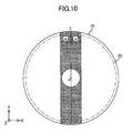
- FIG. 10 is a plan view showing a stabilizing member 31 shown in FIG. 9.
- FIG. 11 is a view for explaining a moving path of a pick-up 26 shown in FIG. 9.
- FIG. 12 is a view for explaining a measurement position of the optical disk 20 at a stabilizing experiment of the disk apparatus 101.
- FIG. 13 is a view for explaining surface vibration of the optical disk 20 when a stabilizing member 31 is used.
- parts that are the same as the parts shown in FIG. 1 through FIG. 8 are given the same reference numerals, and explanation thereof is omitted.
- a disk apparatus 101 includes a motor 22, a spindle shaft 24, a pick-up 26, a stabilizing member 31, a housing 10, and a control device (not shown in FIG. 1).
- the motor 22 has a rotational shaft 22a provided in parallel with a Z axis.
- the spindle shaft 24 is fixed to a +Z end of the rotational shaft 22a of the motor 22.
- the pick-up 26 performs recording and reproducing of information onto and from the optical disk 29.
- the stabilizing member 31 stabilizes rotation of the optical disk 20.
- the housing 10 receives the above-mentioned parts.
- the control device not shown in FIG. 1 controls the pick-up 26 and the motor 22.
- the stabilizing member 31 is, for example, a circular cylinder member having a low height, an external diameter of approximately 125 mm, and a circular shape opening situated in the center with a diameter of approximately 32 mm.
- a -Z surface of the stabilizing member 31 is fixed to a bottom wall surface of the housing 10 via a supporting member (not shown).
- a +Z side surface of the stabilizing member 31 is a curved surface (hereinafter "acting surface") facing the optical disk 20 and has a cylindrically curved convex shaped configuration.
- the acting surface of the stabilizing member 31 has a generating line (hereinafter “center generating line L' ”) passing through the center of the acting surface and being parallel with Y axis.
- the acting surface of the stabilizing member 31 is curved at, for example, a curvature radius of approximately 1000 mm.
- a flat part, an area shaded gray in FIG. 10 is defined by two straight lines parallel with the Y axis and separated from the center generating line L' in -x and +x directions each at a distance S (approximately 17.5 mm in this case) and an external circumference of the acting surface.
- the spindle shaft 24 has a structure where an upper surface of a circular cylinder shaped large diameter part slightly projects from inside of a circular opening part provided in the center of the stabilizing member 31.
- the small diameter part of the spindle shaft 24 is inserted into the round hole of the circular plate 20c and the optical disk 20 is supported from a lower side by the upper surface of the large diameter part, so that the optical disk 20 is attached to the spindle shaft 24 in a state where the recording layer is an upper surface and the center of the optical disk 20 is coincident with the center of the acting surface.
- the optical disk 20 may be attached to the spindle shaft 24 so that a distance between the lower surface on the assumption that the optical disk 20 is flat and the flat part of the acting surface of the stabilizing member 31 is approximately 150 ⁇ m.
- the pick-up 26 is arranged at an upper side (+z side) of the optical disk 20. As shown by arrows a and a' in FIG. 11, the pick-up 26 is driven along a straight line passing through the center of the optical disk 20 at an angle of approximately -10 degrees with the y axis, by a pick-up driving device (not shown). Under this structure, the pick-up 26 moves along a straight line passing through the center of the acting surface of the stabilizing member 30 at an angle of approximately -10 degrees with the center generating line L'.
- the stabilizing member 31 causes the optical disk 20 to generate an aerodynamic force so as to balance the force of restitution generated for the optical disk 20 and the repulsive force.
- surface vibration of the optical disk 20, that is vibration in a direction of a rotational axis of the optical disk 20 can be reduced.
- the inventors of the present invention conducted a stabilizing experiment of the optical disk 20 using the above-discussed stabilizing member 31.
- the stabilizing experiment as shown in FIG. 12, in a state where the optical disk 20 is rotated in the direction shown by an arrow b, amplitudes in the z axis direction generated due to the surface vibration of the optical disk 20 at positions on the circumference encompassing a center angle of 60 degrees are measured.
- the circumference having the center angle of 60 degrees is defined by a point P1 at the -Y side of an external circumference of the optical disk 20, and points P0 and P3 situated at -30 degrees and +30 degrees, respectively, from the point P1.
- FIG. 12 and FIG. 13(A) showing a state of -Y side of the optical disk 20, in the vicinity of a position at an upstream side (P3 side) in the rotational direction of the optical disk 20 of the point P1, a force P2 is applied in a direction so as to separate the stabilizing member 31 from the optical disk 20.
- the stabilizing member 31 does not sufficiently operate on a part separated from the stabilizing member 31.
- FIG. 13(B) shows a tangential profile of surface vibration in positions on the circumference defined by the points P0 through P3. As shown in FIG. 13(B), the surface vibration of the optical disk 20 is locally degraded at the upstream side (P3 side) of the point P1. This phenomenon was confirmed in the vicinity of 4000 rpm as the rotational speed of the optical disk 20. When the rotational speed of the optical disk 20 exceeded 10000 rpm, this phenomenon was remarkable.
- a table 5 included below shows a result of measurement of vibration amplitude ( ⁇ m) of the optical disk 20 at several points, P4, P5, P6, P7, P8, and P9, by using a laser displacement gage in a state where the rotational speed of the optical disk 20 is changed from 4000 rpm to 14000 rpm in 2000 rpm steps.
- the point P4 is situated at approximately 25 mm from the center of the optical disk 20 in the -Y direction.
- the point P5 is situated at approximately 40 mm from the center of the optical disk 20 in the -Y direction.
- the point P6 is situated at approximately 58 mm from the center of the optical disk 20 in the -Y direction.
- the point P7 is situated at approximately 25 mm from the center of the optical disk 20 on the moving path of the pick-up 26.
- the point P8 is situated at approximately 40 mm from the center of the optical disk 20 on the moving path of the pick-up 26.
- the point P9 is situated at approximately 58 mm from the center of the optical disk 20 on the moving path of the pick-up 26.
- the amplitude of the optical disk 20 is equal to or less than approximately 10 ⁇ m and therefore the access precision can be improved.
- the moving path of the pick-up 26 is set along a position where there is little influence due to the surface vibration generated in the optical disk 20 when the information is reproduced or recorded.
- the pick-up 26 moves, as shown in FIG. 11, along the straight line at an angle of approximately -10 degrees with the y axis in the second embodiment of the present invention
- the present invention is not limited to this.
- the pick-up 26 may move along a straight line that is parallel with the y axis and separated from the Y axis at, for example, approximately 10 mm to a downstream side (-x side) in the rotational direction.
- the pick-up 26 moves, as shown in FIG. 11, along the straight line at an angle of approximately 10 degrees with the y axis in the second embodiment of the present invention, the present invention is not limited to this.
- the moving path may be along the Y axis and the center generating line L of the stabilizing member 30 may be at an angle of approximately 10 degrees with the y axis.
- the moving path of the pick-up 26 may be at an angle of approximately -10 degrees with the center generating line L of the stabilizing member 30.
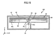
- FIG. 15 is a view of a schematic structure of a disk apparatus 102 of a third embodiment of the present invention.
- FIG. 16 is a view showing a slot 45 formed in a disk cartridge 40 shown in FIG. 15.
- FIG. 17 is a view for explaining a measurement position of the optical disk 20 in a stabilizing experiment on the disk apparatus 102.
- parts that are the same as the parts shown in FIG. 1 through FIG. 8 are given the same reference numerals, and explanation thereof is omitted.
- a disk apparatus 102 includes a motor 22, a spindle shaft 24, a disk cartridge 40, a pick-up 26, a housing 10, and a control device (not shown in FIG. 15).
- the motor 22 has a rotational shaft 22a provided in parallel with a Z axis.
- the spindle shaft 24 is fixed to a +Z end of the rotational shaft 22a of the motor 22.
- the disk cartridge 40 is detachably supported by a supporting member not shown in FIG. 15.
- the pick-up 26 performs recording and reproducing of information onto and from the optical disk 29 accommodated in the disk cartridge 40.
- the housing 10 receives the above-mentioned parts.
- the control device not shown in FIG. 15 controls the pick-up 26 and the motor 22.
- the disk cartridge 40 includes a cover 42 and a base 44 which are engaged with each other, a stabilizing member 30 received in an internal space formed by the cover 42 and the base 44, and an optical disk 20.
- the cover 42 has a plate member having a substantially square configuration.
- the stabilizing member 30, as shown by a dotted line in FIG. 16, is attached on the lower surface of the cover 42 so that the center generating line L and the y axis form an angle of -10 degrees.
- the base 44 has a square configuration as a plan view.
- the base 44 includes a bottom plate part parallel with an XY plan surface and a side wall part provided along an external circumference of the bottom plate part.
- a key hole slot 45 whose longitudinal direction is the direction of the Y axis is formed in the bottom plate part.
- the slot 45 has a structure where a circular shape opening part 45a and a rectangular shape opening part 45b.
- the center of the opening part 45a is coincident with the center of the acting surface of the stabilizing member 30.
- the opening part 45b extends from a -Y side of the opening part 45a to an internal wall surface of the base 44.
- the base 44 is fixed to the lower surface of the cover 42 in a state where the stabilizing member 30 fixed to the lower surface of the cover 42 and the optical disk 20 arranged at a lower part of the stabilizing member 30 are received in a space formed by the bottom plate part and the side wall part of the base 44.
- the optical disk 20 accommodated inside is rotatably supported by the spindle shaft 24 inserted from the lower part of the cartridge 40 via the opening part 45a of the slot 45.
- the optical disk 20 can be accessed by the pick-up 26 via the opening part 45b of the slot 45.
- the control device drives the optical disk 20 to rotate at a designated rotational speed via the motor 22, so that the pick-up 26 moves along the slot 45b of the disk cartridge 44 via the pick-up driving device and information is reproduced or recorded from or onto the recording layer of the optical disk 20.
- a table 6 included below shows a result of measurement, by the inventors of the present invention, of vibration amplitude ( ⁇ m) of the optical disk 20 at several points, P13, P14, and P15, by using a laser displacement gage in a state where the rotational speed of the optical disk 20 is changed from 4000 rpm to 14000 rpm in 2000 rpm steps.
- the point P13 is situated at approximately 25 mm from the center of the optical disk 20 on the moving path of the pick-up 26.
- the point P14 is situated at approximately 40 mm from the center of the optical disk 20 on the moving path of the pick-up 26.
- the point P15 is situated at approximately 58 mm from the center of the optical disk 20 on the moving path of the pick-up 26.
- a table 7 included below shows a result of measurement of tilt angles in a circumferential direction of the optical disk 20 at several points P13, P14, and P15, by using a laser autocollimator in a state where the rotational speed of the optical disk 20 is changed from 4000 rpm to 14000 rpm in 2000 rpm steps.
- the surface vibration of the optical disk 20 at points P13, P14 and P15 are equal to or less than approximately 10 ⁇ m.
- the tilt angles at the points P13, P14 and P15 are approximately 0 degrees ( ⁇ within 0.1 degree).
- the amplitude of the optical disk 20 be equal to or less than approximately 10 ⁇ m and make the tilt angles in the vicinity of the moving path of the optical disk 20 be approximately 0 degrees. Therefore, the access precision of the optical pick-up 26 can be improved.
- the opening part 45b of the slot 45 is formed on the base 44 along a position where influence due to the surface vibration generated in the optical disk 20 occurs when the optical disk 20 is rotated.
- the stabilizing member 30 is provided so that the center generating line L and the slot 45 form a designated angle in the third embodiment of the present invention, the present invention is not limited to this.
- the opening part 45b of the slot 46 may be provided so as to be separated from the center generating line L at approximately 10 mm to an upstream side (+x side) in a rotational direction.
- the disk cartridge 44 includes the stabilizing member 30.
- the disk cartridge 44 may include the stabilizing member 31.
- the stabilizing member 31 may be provided so that the center generating line L' and the Y axis form an angle of approximately 10 degrees.
- the opening part 45b of the slot 46 may be provided so as to be situated at approximately 10 mm to a downstream side (-x side) in the rotational direction of the center generating line L'.
- the external diameter of the stabilizing member 30 or 31 and the curvature radius of the acting surface are just examples. These may be proper values corresponding to the disk in use. For example, as the external diameter of the optical disk is smaller, the external diameter of the stabilizing member 30 or 31 may be smaller.
- the configuration of a proper stabilizing member may be determined by an experiment or simulation.
- the angle formed by the center generating line of the stabilizing member 30 or 31 and the moving path of the pick-up 26, and the distance between the center generating line of the stabilizing member 30 or 31 and the moving path of the pick-up 26, discussed above, are just examples. There is no limitation about this, as long as the pick-up 26 can move on a path defined by a position where the influence of the surface vibration may not be received.
- the stabilizing member 30 or 31 may be formed by, for example, injection molding of plastic or sheet metal working of a metal plate.
- the surface vibration of the optical disk 20 is suppressed by only the stabilizing members 30 and 31 provided at one side of the optical disk 20.
- the present invention is not limited to this.
- a supplemental stabilizing member 32 may be provided, as shown in FIG. 18(A) and FIG. 18(B), at the other side of the optical disk 20.
- FIG. 18 is a view showing modified examples of the disk apparatuses 100 and 102 of the first and third embodiments of the present invention.
- the supplemental stabilizing member 32 has an acting surface having a configuration that is the reverse of the acting surface of the stabilizing member 30 or 31.
- the disk apparatuses 100, 101 and 102 have a single pick-up 26.
- the present invention is not limited to this.
- another pick-up may be provided so as to clamp the spindle shaft 24.
- the disk apparatus 100 can realize high speed transfer using, for example two pick-ups.
- the present invention is not limited to this.
- the present invention can be applied to other flexible disks such as a magnetic disk or a magneto-optical disk.
- the disk apparatus 100, 101 and 102 of the embodiments of the present invention are proper for reproducing or recording information from or onto the flexible disk.
- the disk cartridge 40 of the embodiment of the present invention is proper for receiving the flexible disk.
- a disk apparatus including: a head configured to move along a recording surface of a rotating disk; and a stabilizing member provided so as to face the disk; wherein a facing surface of the stabilizing member facing the disk includes a curved surface whose symmetrical axis is a center generating line passing through a center of the facing surface; and the head reciprocally moves along a path which is offset from the center generating line.
- the facing surface may include a cylindrically curved concave surface; and an area including the center generating line is a flat surface.
- the head reciprocally may move along the path which is offset from the center generating line to an upstream side in a rotational direction of the disk.
- the head reciprocally may move along a recording surface of the disk facing the flat surface.
- the facing surface may include a curved surface whose symmetrical axis is the center generating line; and the head reciprocally may move along a path which is offset from the center generating line to a downstream side in a rotational direction of the disk.
- the facing surface may include a cylindrically curved convex surface; and the head reciprocally may move along a path which is offset from the center generating line to a downstream side in a rotational direction of the disk.
- the path may be offset from the center generating line with respect to at least one of an angle with the center generating line and a distance from the center generating line.
- a disk apparatus including a head configured to move along a recording surface of a rotating disk; and a stabilizing member provided so as to face the disk; wherein a facing surface of the stabilizing member facing the disk includes a cylindrically curved concave surface whose symmetrical axis is a center generating line passing through a center of the facing surface; and an area including the center generating line is a flat surface.
- a disk cartridge including: a casing configured to rotatably accommodate a flexible disk; and a stabilizing member provided so as to face the disk; wherein a facing surface of the stabilizing member facing the disk includes a curved surface whose symmetrical axis is a center generating line passing through a center of the facing surface; and a slot is formed in a position that is offset from the center generating line in the casing; and the slot defines a moving path of a head, the head configured to perform at least one of recording and reproducing information onto and from a recording surface of the disk.
- the facing surface may include a cylindrically curved concave surface; and an area including the center generating line may be a flat surface.
- the slot may be formed in a position offset from the center generating line to an upstream side in a rotational direction of the disk.
- the slot may be formed so as to face the flat surface.
- the facing surface may be a curved surface whose symmetrical axis is the center generating line; and the slot may be formed in a position offset from the center generating line to a downstream side in a rotational direction of the disk.
- the facing surface may includes a cylindrically curved convex surface; and the slot may be formed in a position offset from the center generating line to a downstream side in a rotational direction of the disk.
- the slot may be offset from the center generating line with respect to at least one of an angle with the center generating line and a distance from the center generating line.
- a disk cartridge including: a casing configured to rotatably accommodate a flexible disk; and a stabilizing member provided so as to face a recording surface of the disk; wherein a facing surface of the stabilizing member facing the disk includes a cylindrically curved concave surface whose symmetrical axis is a center generating line passing through a center of the facing surface; and an area including the center generating line is a flat surface.
Landscapes
- Optical Record Carriers And Manufacture Thereof (AREA)
- Moving Of The Head For Recording And Reproducing By Optical Means (AREA)
Applications Claiming Priority (3)
| Application Number | Priority Date | Filing Date | Title |
|---|---|---|---|
| JP2005265002 | 2005-09-13 | ||
| JP2005317913 | 2005-11-01 | ||
| JP2006146059A JP4688217B2 (ja) | 2005-09-13 | 2006-05-26 | ディスク装置及びディスクカートリッジ |
Publications (2)
| Publication Number | Publication Date |
|---|---|
| EP1763025A1 true EP1763025A1 (de) | 2007-03-14 |
| EP1763025B1 EP1763025B1 (de) | 2008-07-30 |
Family
ID=37564152
Family Applications (1)
| Application Number | Title | Priority Date | Filing Date |
|---|---|---|---|
| EP06254772A Not-in-force EP1763025B1 (de) | 2005-09-13 | 2006-09-13 | Vorrichtung und Datenträgerkassette |
Country Status (4)
| Country | Link |
|---|---|
| US (1) | US7823172B2 (de) |
| EP (1) | EP1763025B1 (de) |
| JP (1) | JP4688217B2 (de) |
| DE (1) | DE602006002008D1 (de) |
Cited By (1)
| Publication number | Priority date | Publication date | Assignee | Title |
|---|---|---|---|---|
| EP2101324A1 (de) * | 2008-03-14 | 2009-09-16 | Ricoh Company, Ltd. | Aufzeichnungs-/Wiedergabevorrichtung und Aufzeichnungs-/Wiedergabeverfahren |
Families Citing this family (6)
| Publication number | Priority date | Publication date | Assignee | Title |
|---|---|---|---|---|
| US8259543B2 (en) | 2007-05-21 | 2012-09-04 | Ricoh Company, Ltd. | Data recording/reproduction method and data recording/reproduction apparatus |
| JP5027620B2 (ja) * | 2007-11-07 | 2012-09-19 | 株式会社日立エルジーデータストレージ | 光情報記録再生装置およびターンテーブル |
| KR101105861B1 (ko) | 2008-03-13 | 2012-01-16 | 가부시키가이샤 리코 | 디스크 회전 장치, 기록 재생 장치 및 가요성 디스크 |
| JP5235457B2 (ja) * | 2008-03-14 | 2013-07-10 | 株式会社リコー | 記録再生装置、ディスク組立体、及びディスクカートリッジ |
| JP5249613B2 (ja) * | 2008-03-13 | 2013-07-31 | 株式会社リコー | ディスク回転機構、ディスク、記録再生装置、及び記録再生方法 |
| JP5864308B2 (ja) * | 2012-03-07 | 2016-02-17 | 日本放送協会 | 光ディスク装置、ギャップサーボ装置及びギャップ引き込み制御方法 |
Citations (3)
| Publication number | Priority date | Publication date | Assignee | Title |
|---|---|---|---|---|
| FR2002946A1 (de) * | 1968-02-29 | 1969-10-31 | Telefunken Gmbh | |
| US3830506A (en) * | 1971-12-11 | 1974-08-20 | Ted Bildplatten | Foil record carrier |
| US4167269A (en) * | 1976-09-30 | 1979-09-11 | International Business Machines Corporation | Flexible record disk signal storage apparatus |
Family Cites Families (12)
| Publication number | Priority date | Publication date | Assignee | Title |
|---|---|---|---|---|
| BE792354A (fr) * | 1971-12-11 | 1973-03-30 | Ted Bildplatten | Appareil d'enregistrement et/ou de reproduction pour une feuille flexible de porteur d'enregistrement |
| JPS524212A (en) * | 1975-06-28 | 1977-01-13 | Canon Inc | Magnet sheet unit |
| US4057840A (en) * | 1976-01-07 | 1977-11-08 | Texas Instruments Incorporated | Flexible disc recording cartridge |
| JPS53112710A (en) * | 1977-03-14 | 1978-10-02 | Mitsubishi Electric Corp | Flexible disc apparatus |
| US4208683A (en) * | 1978-12-13 | 1980-06-17 | International Business Machines Corporation | Frusto-conical magnetic recording disc |
| EP0457459A3 (en) * | 1990-05-18 | 1992-12-02 | Imperial Chemical Industries Plc | Minimising focus error in optical information storage systems |
| JP2001209981A (ja) | 1999-02-09 | 2001-08-03 | Ricoh Co Ltd | 光ディスク基板成膜装置、光ディスク基板成膜方法、基板ホルダーの製造方法、基板ホルダー、光ディスクおよび相変化記録型光ディスク |
| US7233554B2 (en) * | 2001-04-17 | 2007-06-19 | Ricoh Company, Ltd. | Disk drive system employing effective disk surface stabilization mechanism |
| JP4190745B2 (ja) * | 2001-07-06 | 2008-12-03 | 株式会社リコー | 光ディスク駆動装置および光学的情報記録装置ならびに光学的情報再生装置 |
| US7164629B2 (en) | 2002-01-22 | 2007-01-16 | Ricoh Company, Ltd. | Method of controlling an optical disk apparatus |
| US7194750B2 (en) * | 2003-01-28 | 2007-03-20 | Ricoh Company, Ltd. | Recording/reproducing apparatus and disk cartridge |
| JP2005050404A (ja) * | 2003-07-30 | 2005-02-24 | Ricoh Co Ltd | 記録/再生装置およびその制御調整方法 |
-
2006
- 2006-05-26 JP JP2006146059A patent/JP4688217B2/ja not_active Expired - Fee Related
- 2006-09-08 US US11/517,486 patent/US7823172B2/en not_active Expired - Fee Related
- 2006-09-13 DE DE602006002008T patent/DE602006002008D1/de active Active
- 2006-09-13 EP EP06254772A patent/EP1763025B1/de not_active Not-in-force
Patent Citations (3)
| Publication number | Priority date | Publication date | Assignee | Title |
|---|---|---|---|---|
| FR2002946A1 (de) * | 1968-02-29 | 1969-10-31 | Telefunken Gmbh | |
| US3830506A (en) * | 1971-12-11 | 1974-08-20 | Ted Bildplatten | Foil record carrier |
| US4167269A (en) * | 1976-09-30 | 1979-09-11 | International Business Machines Corporation | Flexible record disk signal storage apparatus |
Cited By (3)
| Publication number | Priority date | Publication date | Assignee | Title |
|---|---|---|---|---|
| EP2101324A1 (de) * | 2008-03-14 | 2009-09-16 | Ricoh Company, Ltd. | Aufzeichnungs-/Wiedergabevorrichtung und Aufzeichnungs-/Wiedergabeverfahren |
| US8077576B2 (en) | 2008-03-14 | 2011-12-13 | Ricoh Company, Ltd. | Optimum gap determined recording/reproducing apparatus and method |
| US8228772B2 (en) | 2008-03-14 | 2012-07-24 | Ricoh Company, Ltd. | Optimum gap determined recording/reproducing apparatus |
Also Published As
| Publication number | Publication date |
|---|---|
| EP1763025B1 (de) | 2008-07-30 |
| DE602006002008D1 (de) | 2008-09-11 |
| US7823172B2 (en) | 2010-10-26 |
| US20070061828A1 (en) | 2007-03-15 |
| JP4688217B2 (ja) | 2011-05-25 |
| JP2007149311A (ja) | 2007-06-14 |
Similar Documents
| Publication | Publication Date | Title |
|---|---|---|
| EP1763025B1 (de) | Vorrichtung und Datenträgerkassette | |
| EP1422699B1 (de) | Verfahren zur einstellung der neigung einer führungswelle in einer aufzeichnungsmediumsansteuereinrichtung | |
| US7367036B2 (en) | Recording/reproduction apparatus, driving method therefor and disk cartridge | |
| JP2006107699A (ja) | 記録/再生装置およびその駆動方法ならびにディスクカートリッジ | |
| JP4087639B2 (ja) | 光ディスク駆動安定化装置および光ディスク装置 | |
| JP4123464B2 (ja) | 光学的記録/再生装置の制御方法および光学的記録/再生装置 | |
| JP4721271B2 (ja) | ディスク装置及びディスクカートリッジ | |
| JP4199059B2 (ja) | 記録/再生装置および安定化調整方法 | |
| JP2006107698A (ja) | 記録/再生装置およびその駆動方法 | |
| EP1705649A1 (de) | optisches Plattengerät mit Einstellungsanordnung für die Plattenpositionierung | |
| JPH10269641A (ja) | ヘッド装置 | |
| JP2003022651A (ja) | 光ディスク駆動装置および光学的情報記録装置ならびに光学的情報再生装置 | |
| JP4035318B2 (ja) | 光ディスク装置 | |
| JP4223381B2 (ja) | 記録/再生装置およびディスクカートリッジ | |
| JP5524545B2 (ja) | フレキシブルディスクシステムおよびフレキシブルディスクの製造方法 | |
| JPH10208373A (ja) | 光ピックアップ装置 | |
| JP4145514B2 (ja) | 光ディスク駆動装置の制御方法、光ディスク駆動装置および光学的記録/再生装置の制御方法ならびに光学的記録/再生装置 | |
| JP4495362B2 (ja) | 光ディスク装置 | |
| JP4181053B2 (ja) | 記録/再生装置 | |
| JP2005050404A (ja) | 記録/再生装置およびその制御調整方法 | |
| CN101145357A (zh) | 盘驱动装置 | |
| JPH097204A (ja) | 情報蓄積装置の対物レンズ支持装置 | |
| JP2005044401A (ja) | 記録/再生装置およびディスクカートリッジ | |
| JP2003217263A (ja) | 光ディスク装置およびその調整方法 | |
| JP2005018957A (ja) | 記録/再生装置およびディスクカートリッジ |
Legal Events
| Date | Code | Title | Description |
|---|---|---|---|
| PUAI | Public reference made under article 153(3) epc to a published international application that has entered the european phase |
Free format text: ORIGINAL CODE: 0009012 |
|
| 17P | Request for examination filed |
Effective date: 20060920 |
|
| AK | Designated contracting states |
Kind code of ref document: A1 Designated state(s): AT BE BG CH CY CZ DE DK EE ES FI FR GB GR HU IE IS IT LI LT LU LV MC NL PL PT RO SE SI SK TR |
|
| AX | Request for extension of the european patent |
Extension state: AL BA HR MK YU |
|
| 17Q | First examination report despatched |
Effective date: 20070504 |
|
| GRAP | Despatch of communication of intention to grant a patent |
Free format text: ORIGINAL CODE: EPIDOSNIGR1 |
|
| AKX | Designation fees paid |
Designated state(s): DE ES FR GB IT NL |
|
| GRAS | Grant fee paid |
Free format text: ORIGINAL CODE: EPIDOSNIGR3 |
|
| GRAA | (expected) grant |
Free format text: ORIGINAL CODE: 0009210 |
|
| AK | Designated contracting states |
Kind code of ref document: B1 Designated state(s): DE ES FR GB IT NL |
|
| REG | Reference to a national code |
Ref country code: GB Ref legal event code: FG4D |
|
| REF | Corresponds to: |
Ref document number: 602006002008 Country of ref document: DE Date of ref document: 20080911 Kind code of ref document: P |
|
| PG25 | Lapsed in a contracting state [announced via postgrant information from national office to epo] |
Ref country code: ES Free format text: LAPSE BECAUSE OF FAILURE TO SUBMIT A TRANSLATION OF THE DESCRIPTION OR TO PAY THE FEE WITHIN THE PRESCRIBED TIME-LIMIT Effective date: 20081110 |
|
| PLBE | No opposition filed within time limit |
Free format text: ORIGINAL CODE: 0009261 |
|
| STAA | Information on the status of an ep patent application or granted ep patent |
Free format text: STATUS: NO OPPOSITION FILED WITHIN TIME LIMIT |
|
| 26N | No opposition filed |
Effective date: 20090506 |
|
| PG25 | Lapsed in a contracting state [announced via postgrant information from national office to epo] |
Ref country code: IT Free format text: LAPSE BECAUSE OF FAILURE TO SUBMIT A TRANSLATION OF THE DESCRIPTION OR TO PAY THE FEE WITHIN THE PRESCRIBED TIME-LIMIT Effective date: 20080730 |
|
| REG | Reference to a national code |
Ref country code: FR Ref legal event code: PLFP Year of fee payment: 11 |
|
| PGFP | Annual fee paid to national office [announced via postgrant information from national office to epo] |
Ref country code: NL Payment date: 20160920 Year of fee payment: 11 Ref country code: GB Payment date: 20160920 Year of fee payment: 11 Ref country code: DE Payment date: 20160921 Year of fee payment: 11 |
|
| PGFP | Annual fee paid to national office [announced via postgrant information from national office to epo] |
Ref country code: FR Payment date: 20160921 Year of fee payment: 11 |
|
| REG | Reference to a national code |
Ref country code: DE Ref legal event code: R119 Ref document number: 602006002008 Country of ref document: DE |
|
| REG | Reference to a national code |
Ref country code: NL Ref legal event code: MM Effective date: 20171001 |
|
| GBPC | Gb: european patent ceased through non-payment of renewal fee |
Effective date: 20170913 |
|
| PG25 | Lapsed in a contracting state [announced via postgrant information from national office to epo] |
Ref country code: NL Free format text: LAPSE BECAUSE OF NON-PAYMENT OF DUE FEES Effective date: 20171001 |
|
| REG | Reference to a national code |
Ref country code: FR Ref legal event code: ST Effective date: 20180531 |
|
| PG25 | Lapsed in a contracting state [announced via postgrant information from national office to epo] |
Ref country code: DE Free format text: LAPSE BECAUSE OF NON-PAYMENT OF DUE FEES Effective date: 20180404 Ref country code: GB Free format text: LAPSE BECAUSE OF NON-PAYMENT OF DUE FEES Effective date: 20170913 |
|
| PG25 | Lapsed in a contracting state [announced via postgrant information from national office to epo] |
Ref country code: FR Free format text: LAPSE BECAUSE OF NON-PAYMENT OF DUE FEES Effective date: 20171002 |