EP1763090A2 - Réseau de diodes électroluminescentes avec des moyens de refroidissement - Google Patents
Réseau de diodes électroluminescentes avec des moyens de refroidissement Download PDFInfo
- Publication number
- EP1763090A2 EP1763090A2 EP20060076664 EP06076664A EP1763090A2 EP 1763090 A2 EP1763090 A2 EP 1763090A2 EP 20060076664 EP20060076664 EP 20060076664 EP 06076664 A EP06076664 A EP 06076664A EP 1763090 A2 EP1763090 A2 EP 1763090A2
- Authority
- EP
- European Patent Office
- Prior art keywords
- led array
- cooling system
- substrate
- heat sink
- array cooling
- Prior art date
- Legal status (The legal status is an assumption and is not a legal conclusion. Google has not performed a legal analysis and makes no representation as to the accuracy of the status listed.)
- Withdrawn
Links
Images




Classifications
-
- H—ELECTRICITY
- H10—SEMICONDUCTOR DEVICES; ELECTRIC SOLID-STATE DEVICES NOT OTHERWISE PROVIDED FOR
- H10H—INORGANIC LIGHT-EMITTING SEMICONDUCTOR DEVICES HAVING POTENTIAL BARRIERS
- H10H20/00—Individual inorganic light-emitting semiconductor devices having potential barriers, e.g. light-emitting diodes [LED]
- H10H20/80—Constructional details
- H10H20/85—Packages
- H10H20/858—Means for heat extraction or cooling
- H10H20/8586—Means for heat extraction or cooling comprising fluids, e.g. heat-pipes
-
- H—ELECTRICITY
- H10—SEMICONDUCTOR DEVICES; ELECTRIC SOLID-STATE DEVICES NOT OTHERWISE PROVIDED FOR
- H10W—GENERIC PACKAGES, INTERCONNECTIONS, CONNECTORS OR OTHER CONSTRUCTIONAL DETAILS OF DEVICES COVERED BY CLASS H10
- H10W90/00—Package configurations
Definitions
- This invention generally relates to heat transfer systems and more particularly relates to systems for cooling LED arrays.
- Infrared cameras depend on infrared light emitted from LED arrays to illuminate the subject whose image is being captured by the infrared camera. Infrared cameras are often used in imaging applications associated with vehicle safety systems to determine the presence (or absence) of a passenger in one or more locations within a vehicle. Infrared imaging systems are also used in automobile applications in what is known as “driver gaze systems.” Driver gaze systems are systems that monitor driver eye and head movement to determine if the driver is falling asleep or otherwise becoming inattentive to his driving responsibilities.
- infrared cameras can operate at an optimal efficiency only if the light received by the camera falls within an optimum wavelength range. If an infrared camera is operated outside of its optimum wavelength range, its efficiency degrades significantly. For example, many infrared cameras operate optimally in a wavelength band centered around 940 nm. In order to obtain the optimal performance from the infrared camera, the infrared LED array used to illuminate the subject, should have a spectral irradiance maximum centered on or about the 940 nm wavelength point.
- the present invention takes advantage of the moderating temperatures provided by the HVAC system within the vehicle to moderate the temperature of the LED array.
- a LED array cooling system comprising: a LED array (12), a substrate (28) attached to said LED array (12), wherein said LED array (12) includes a plurality of walls that at least in part define a plurality of passages (40) through said LED array (12).
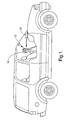
- Figure 1 depicts one possible use for the present invention.
- vehicle subject 14 is a passenger and infrared camera 10 is used to determine if a passenger is in fact present in various locations of the vehicle. If passengers are not present, various strategies may be used in the event of a collision, such as not deploying a side airbag if a passenger is not present within the zone of protection offered by the side airbag.
- the present invention has application in driver gaze systems or in any system where the performance of an imaging camera is tightly coupled to the radiance intensity and wavelength of light emitted by an irradiating device.
- infrared cameras are highly dependent upon wavelengths of infrared light received by the camera. Many infrared cameras operate at peak efficiency when they receive a range of light that is closely centered about a wavelength of 940 nm. Although it is not difficult to fabricate LED arrays that emit light tightly centered at or around the wavelength matched to infrared cameras, infrared irradiating devices are highly susceptible to temperature drift which skews not only the efficiency of the irradiating device (i.e. its strength of irradiance), but also its ability to fix its output light at a center wavelength which is matched to the peak operating wavelength of the infrared camera.
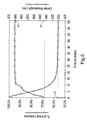
- Figure 2 depicts the typical skewing of irradiance and center wavelength which takes place as an infrared irradiating device heats up.
- the infrared irradiating device when the infrared irradiating device is first powered at its optimal ambient temperature, it, by definition, emits 100 percent of its irradiance. For the particular infrared irradiating device that was tested (Vishay TSAL 6100 940 nm), the emitted light had an initial center wavelength of 942 nm (see reference numeral 20 in Figure 2). The device under test was allowed to warm up over the next hour.
- the irradiance dropped to less than sixty percent (of initial irradiance - see reference numeral 22 in Figure 2) and the center wavelength of the light emitted from the irradiating device shifted from its initial center wavelength of approximately 942 nm to a center wavelength end point of over 965 nm (see reference numeral 24).
- initial irradiance see reference numeral 22 in Figure 2
- center wavelength of the light emitted from the irradiating device shifted from its initial center wavelength of approximately 942 nm to a center wavelength end point of over 965 nm (see reference numeral 24).
- the irradiance of the infrared LED device degrades and secondly the center wavelength of infrared light emitted from the LED device, shifts from a desirable center wavelength (approximately 940 nm) to a less desirable center wavelength (slightly over 965 nm).
- the present invention is employed to use the temperature controls provided by the HVAC system of the vehicle to control the temperature of the infrared LED irradiating device such that the undesirable degradation in irradiance is minimized and the undesirable shift in center wavelength of light emitted from the infrared irradiating device is also minimized.
- the present invention includes an infrared array 12.
- Infrared array 12 is shown in Figure 3 as a generally planar arrangement wherein LEDs are arranged in a generally planar relationship; however, other geometrical arrangements of LEDs such as spherical, cylindrical, cubical, and the like are contemplated by the present invention.
- infrared array 12 is composed of a plurality of LEDs 26 mounted to a common substrate 28.
- LED 26 can be comprised of any number of materials (e.g. silicon) commonly used for fabricating semiconductors (if the LEDs are formed directly to an integrated circuit (IC) in the IC fabrication process).
- substrate 28 may be comprised of any material used for fabricating printed circuit boards such as silicon nitride (SiN), alumina (AlN), FR4 and the like.
- Substrate 28 may be covered in part, or in whole, by an electrically conductive material 30 (such as a copper or aluminum cladding), to provide one or more electrical circuit paths to LED 26 or other electronic components that may be mounted to substrate 28.
- an electrically conductive material 30 such as a copper or aluminum cladding
- Lens 32 is disposed over LED 26 and forms a device for directing the path of light emitted from LED 26.
- Lens 32 can be formed directly on substrate 28 during the process of fabricating infrared array 12 or in the alternative, lens 32 may be fabricated separately and then subsequently overlaid upon substrate 28 and LED 26.
- Each lens 32 may be separate from one another or two or more lenses may be fabricated in a common lens layer 32'.
- Manifold 34 forms a heat sink for drawing heat away from substrate 28.
- a thermally conductive material 36 can be placed between manifold 34 and substrate 28.
- Manifold 34 can be fashioned with a plurality of fins 38 so that the surface area of manifold 34 can be increased thereby increasing the capacity of manifold 32 to shed heat. Walls formed in manifold 34 define in part, passages 40.
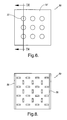
- Infrared array 12 preferably includes passages 40 that pass between adjacent lenses 32 (through lens sheet 32'), through substrate 28, and through manifold heat sink 34. These passages may be formed through infrared array 12 at any location which does not interfere with the operation of LED 12 or the function of lens 32. Walls formed in substrate 28 define, in part, passages 40. In the embodiment shown in Figures 3 and 4A, passages 40 are placed between horizontally adjacent LEDs (exemplified at 42 in Figure 3) and also placed between vertically adjacent LEDs (exemplified at 44 in Figure 3). Other or additional placement of openings 40 is contemplated by the present invention such as the placement of openings 44 between diagonally adjacent LEDs.
- the fin portion 38 of manifold 34 can extend at a 90° angle 42 from the plane 44 of substrate 28. Additionally, it is contemplated in the present invention that other manifold extension geometries can be used. For example, fin 38 can extend at a 45° angle if packaging depth is an issue.
- Air movement 46 can be accomplished in any number of ways through passages 40. For example, depending on the heat load generated by LEDs 26, simple air movement caused by convection may be sufficient to cool manifold 34. In instances where convection cooling is insufficient to remove the heat absorbed by manifold 34, a motor 48 and fan 50 assembly may be used to move air through passages 40. If packaging constraints do not allow motor/fan assembly 48, 50 to be placed directly adjacent manifold 34, a conduit 52 can be interposed between fan 50 and passages 40. By using conduit 52 in this manner, fan 50 may be remotely mounted from passages 40.
- motor 48 is connected to thermal controller 54.
- Thermal controller 54 is capable of varying the speed at which motor 48 turns.
- Thermal controller 54 is coupled to thermal sensor 56.
- Thermal sensor 56 is mounted to a portion of manifold 34 and is capable of sensing the temperature of manifold 34 and generating an electrical signal which is indicative of the temperature of manifold 34.
- Thermal controller 54 may be adapted to control the speed of motor 48 in proportion to the temperature deviation between the temperature sensed by sensor 56 and a predetermined thermal set point.
- the predetermined thermal set point can be preset within thermal controller 54 or it can be externally set and/or externally adjustable.
- thermal isolators 58 can be used as thermal insulation members to impede heat flow to or from infrared array 12.
- infrared array 60 is formed without openings 40 (which in the embodiment of Figures 3-6, pass through lens layer 32').
- manifold 34 includes a plurality of pegs 60 that extend from manifold 34. Each peg 60 is designed to reside within a respectively associated aperture 62 formed by adjacent side walls 29' of substrate 28 (see aperture 62 in Figure 7B).
- Substrate 28 can optionally include a cladding material 30 (such as electrically conductive metal).
- Aperture 62 should be formed sufficiently large to eliminate cracking of peg 60 or the substrate 28 due to the differences in the coefficient of thermal expansion between manifold material 34 and substrate material 28.
- thermally conductive paste 36 may be disposed between manifold 34 and substrate 28 in order to enhance the heat transfer from substrate 28 to manifold 34 and also to enhance the heat flow from substrate 28 to peg 60.
- a supplemental fluid cooling scheme may be used to cool manifold 34.
- the fluid medium can be any fluid (liquid or gas) effective for transferring heat.
- manifold 34 may be fashioned with one or more chambers 64 which are in fluid connection with one another and also are in fluid connection with a cooling circuit comprised of pump 66, one or more fluid conduit portions 74, and a heat dump device 68.
- the heat dump device 68 can be anything which is capable of dumping the heat load generated by infrared array 60 including a simple copper tube, a radiating device (similar to that used in automotive radiators) and the like.
- pump 66 In the simplest control scheme, pump 66 is allowed to run continuously offering maximum cooling to manifold 34. In an alternative, more sophisticated control scheme, pump 66 is coupled to pump controller 70. Pump controller 70 is adapted to regulate the pumping action of pump 66 which, in turn, controls the flow of fluid circulated by pump 66 through circuit (64, 66, 68, 74). Pump controller 70 monitors the temperature of substrate 28 by way of one or more temperature sensors 72 placed in thermal contact with substrate 28 or manifold 34. Pump controller can use any number of schemes for controlling the activity of pump 66. One such approach that may be used by a pump controller is to monitor the temperature difference between the temperature sensed by sensor 72 and a predetermined temperature.
- pump controller When this temperature difference exceeds a predetermined threshold, pump controller would activate pump 66 thereby circulating fluid through circuit 64, 66, 68 and 74.
- Other, more sophisticated control schemes could be employed such as activating pump 66 in proportion to the magnitude of the temperature difference between temperature sensor 72 and a predetermined temperature. Temperature control approaches such as these are well known to those skilled in the art and any number of control schemes may be used.
Landscapes
- Led Device Packages (AREA)
- Studio Devices (AREA)
- Arrangement Of Elements, Cooling, Sealing, Or The Like Of Lighting Devices (AREA)
- Devices For Indicating Variable Information By Combining Individual Elements (AREA)
Applications Claiming Priority (1)
| Application Number | Priority Date | Filing Date | Title |
|---|---|---|---|
| US11/225,288 US7821123B2 (en) | 2005-09-13 | 2005-09-13 | LED array cooling system |
Publications (2)
| Publication Number | Publication Date |
|---|---|
| EP1763090A2 true EP1763090A2 (fr) | 2007-03-14 |
| EP1763090A3 EP1763090A3 (fr) | 2012-05-02 |
Family
ID=37467593
Family Applications (1)
| Application Number | Title | Priority Date | Filing Date |
|---|---|---|---|
| EP20060076664 Withdrawn EP1763090A3 (fr) | 2005-09-13 | 2006-09-01 | Réseau de diodes électroluminescentes avec des moyens de refroidissement |
Country Status (2)
| Country | Link |
|---|---|
| US (1) | US7821123B2 (fr) |
| EP (1) | EP1763090A3 (fr) |
Cited By (5)
| Publication number | Priority date | Publication date | Assignee | Title |
|---|---|---|---|---|
| WO2009039907A1 (fr) | 2007-09-24 | 2009-04-02 | Ledon Lighting Gmbh | Corps de refroidissement et système de refroidissement pour un module de led |
| CN102054829A (zh) * | 2010-11-05 | 2011-05-11 | 深圳市华星光电技术有限公司 | 发光二极管封装构造 |
| CN101886802B (zh) * | 2009-05-12 | 2012-03-21 | 建准电机工业股份有限公司 | 灯具 |
| CN101996983B (zh) * | 2009-08-21 | 2013-01-23 | 深圳华映显示科技有限公司 | 一种发光二极管封装结构和支架结构 |
| EP2694870A4 (fr) * | 2011-04-08 | 2015-05-06 | Brite Shot Inc | Ensemble d'éclairage à barrette de del |
Families Citing this family (9)
| Publication number | Priority date | Publication date | Assignee | Title |
|---|---|---|---|---|
| US20080002858A1 (en) * | 2006-06-15 | 2008-01-03 | Rafael - Armament Development Authority Ltd. | Photogrammetric mapping of inaccessible terrain |
| US7922360B2 (en) * | 2007-02-14 | 2011-04-12 | Cree, Inc. | Thermal transfer in solid state light emitting apparatus and methods of manufacturing |
| CN101392896A (zh) * | 2007-09-21 | 2009-03-25 | 富士迈半导体精密工业(上海)有限公司 | 发光二极管 |
| JP5160992B2 (ja) * | 2008-07-24 | 2013-03-13 | 株式会社小糸製作所 | 車両用灯具 |
| WO2010010495A1 (fr) * | 2008-07-25 | 2010-01-28 | Koninklijke Philips Electronics N.V. | Dispositif de refroidissement permettant de refroidir une puce à semi-conducteurs |
| US20100277048A1 (en) * | 2009-07-20 | 2010-11-04 | Bridgelux, Inc. | Solid state lighting device with an integrated fan |
| US9357592B2 (en) * | 2010-11-18 | 2016-05-31 | Phoseon Technology, Inc. | Light source temperature monitor and control |
| US9845943B2 (en) * | 2011-07-22 | 2017-12-19 | Guardian Glass, LLC | Heat management subsystems for LED lighting systems, LED lighting systems including heat management subsystems, and/or methods of making the same |
| US11153950B2 (en) | 2019-02-14 | 2021-10-19 | Orlaco Products B.V. | Replacement mirror system with IR LED overheating management |
Citations (3)
| Publication number | Priority date | Publication date | Assignee | Title |
|---|---|---|---|---|
| US6154362A (en) | 1997-04-18 | 2000-11-28 | Sony Corporation | Display apparatus |
| WO2004019657A2 (fr) | 2002-08-26 | 2004-03-04 | Popovich John M | Ensemble/systeme electronique a cout, masse et volume reduits et presentant une meilleure efficacite et densite de puissance |
| WO2005038935A1 (fr) | 2003-10-15 | 2005-04-28 | Nichia Corporation | Dispositif électroluminescent |
Family Cites Families (9)
| Publication number | Priority date | Publication date | Assignee | Title |
|---|---|---|---|---|
| US20050279949A1 (en) * | 1999-05-17 | 2005-12-22 | Applera Corporation | Temperature control for light-emitting diode stabilization |
| US6535398B1 (en) * | 2000-03-07 | 2003-03-18 | Fujitsu Limited | Multichip module substrates with buried discrete capacitors and components and methods for making |
| US6936855B1 (en) * | 2002-01-16 | 2005-08-30 | Shane Harrah | Bendable high flux LED array |
| US7211299B2 (en) * | 2003-01-09 | 2007-05-01 | Con-Trol-Cure, Inc. | UV curing method and apparatus |
| US7137696B2 (en) * | 2003-01-09 | 2006-11-21 | Con-Trol-Cure, Inc. | Ink jet UV curing |
| JP4102240B2 (ja) * | 2003-04-08 | 2008-06-18 | 株式会社小糸製作所 | 車両用前照灯 |
| JP2005044698A (ja) * | 2003-07-24 | 2005-02-17 | Koito Mfg Co Ltd | 車両用灯具及び光源モジュール |
| DE102004018476B4 (de) * | 2004-04-16 | 2009-06-18 | Infineon Technologies Ag | Leistungshalbleiteranordnung mit kontaktierender Folie und Anpressvorrichtung |
| US7237936B1 (en) * | 2005-05-27 | 2007-07-03 | Gibson David J | Vehicle light assembly and its associated method of manufacture |
-
2005
- 2005-09-13 US US11/225,288 patent/US7821123B2/en active Active
-
2006
- 2006-09-01 EP EP20060076664 patent/EP1763090A3/fr not_active Withdrawn
Patent Citations (3)
| Publication number | Priority date | Publication date | Assignee | Title |
|---|---|---|---|---|
| US6154362A (en) | 1997-04-18 | 2000-11-28 | Sony Corporation | Display apparatus |
| WO2004019657A2 (fr) | 2002-08-26 | 2004-03-04 | Popovich John M | Ensemble/systeme electronique a cout, masse et volume reduits et presentant une meilleure efficacite et densite de puissance |
| WO2005038935A1 (fr) | 2003-10-15 | 2005-04-28 | Nichia Corporation | Dispositif électroluminescent |
Cited By (5)
| Publication number | Priority date | Publication date | Assignee | Title |
|---|---|---|---|---|
| WO2009039907A1 (fr) | 2007-09-24 | 2009-04-02 | Ledon Lighting Gmbh | Corps de refroidissement et système de refroidissement pour un module de led |
| CN101886802B (zh) * | 2009-05-12 | 2012-03-21 | 建准电机工业股份有限公司 | 灯具 |
| CN101996983B (zh) * | 2009-08-21 | 2013-01-23 | 深圳华映显示科技有限公司 | 一种发光二极管封装结构和支架结构 |
| CN102054829A (zh) * | 2010-11-05 | 2011-05-11 | 深圳市华星光电技术有限公司 | 发光二极管封装构造 |
| EP2694870A4 (fr) * | 2011-04-08 | 2015-05-06 | Brite Shot Inc | Ensemble d'éclairage à barrette de del |
Also Published As
| Publication number | Publication date |
|---|---|
| US7821123B2 (en) | 2010-10-26 |
| US20070057267A1 (en) | 2007-03-15 |
| EP1763090A3 (fr) | 2012-05-02 |
Similar Documents
| Publication | Publication Date | Title |
|---|---|---|
| US7821123B2 (en) | LED array cooling system | |
| JP6509256B2 (ja) | 車両のアシスタント・システム | |
| US8911125B2 (en) | Circuit module, light emitting module, and automotive lamp | |
| EP2860440B1 (fr) | Dispositif de refroidissement pour un phare de véhicule | |
| US8070324B2 (en) | Thermal control system for a light-emitting diode fixture | |
| US10597002B1 (en) | Imaging system | |
| US7852630B2 (en) | Heat dissipating device | |
| JP2008515207A (ja) | Ledアレイ | |
| US20160307953A1 (en) | Imaging device and circuit board therefor | |
| JP2008524045A (ja) | 自動車用ヘッドライトエレメント | |
| EP1810348B1 (fr) | Dispositif d'eclairage | |
| CN111837056A (zh) | 冷却装置 | |
| KR101413509B1 (ko) | 다수의 히트싱크가 구비된 엘이디 방열체 | |
| US10907794B2 (en) | Headlight assembly with lens heater | |
| CN209909794U (zh) | 冷却单元以及车辆用灯具 | |
| JP6937923B2 (ja) | 車載カメラ装置 | |
| CN101995009A (zh) | 用于模块化发光二极管照明配件的冷却系统 | |
| JP2001043728A (ja) | 発光ダイオード照明装置 | |
| KR20160081434A (ko) | 열전모듈 및 이를 구비하는 차량용 시트 냉난방장치 | |
| KR20090029123A (ko) | 자동차 led 헤드 램프 냉각 장치 및 방법 | |
| US11508892B2 (en) | Folded heatsink design for thermal challenging LED applications | |
| JP6451758B2 (ja) | 車両用灯具 | |
| KR101275530B1 (ko) | 헤드 라이트의 제습용 내부 쿨링 장치 | |
| JP4538278B2 (ja) | 内視鏡装置 | |
| WO2023014966A1 (fr) | Atténuation de la chaleur pour ensemble rétroviseur |
Legal Events
| Date | Code | Title | Description |
|---|---|---|---|
| PUAI | Public reference made under article 153(3) epc to a published international application that has entered the european phase |
Free format text: ORIGINAL CODE: 0009012 |
|
| AK | Designated contracting states |
Kind code of ref document: A2 Designated state(s): AT BE BG CH CY CZ DE DK EE ES FI FR GB GR HU IE IS IT LI LT LU LV MC NL PL PT RO SE SI SK TR |
|
| AX | Request for extension of the european patent |
Extension state: AL BA HR MK YU |
|
| RAP1 | Party data changed (applicant data changed or rights of an application transferred) |
Owner name: ESTERPALL B.V., LLC |
|
| PUAL | Search report despatched |
Free format text: ORIGINAL CODE: 0009013 |
|
| AK | Designated contracting states |
Kind code of ref document: A3 Designated state(s): AT BE BG CH CY CZ DE DK EE ES FI FR GB GR HU IE IS IT LI LT LU LV MC NL PL PT RO SE SI SK TR |
|
| AX | Request for extension of the european patent |
Extension state: AL BA HR MK RS |
|
| RIC1 | Information provided on ipc code assigned before grant |
Ipc: H01L 33/64 20100101AFI20120329BHEP |
|
| 17P | Request for examination filed |
Effective date: 20121102 |
|
| AKX | Designation fees paid |
Designated state(s): AT BE BG CH CY LI |
|
| REG | Reference to a national code |
Ref country code: DE Ref legal event code: R108 |
|
| RBV | Designated contracting states (corrected) |
Designated state(s): AT BE BG CH CY CZ DE DK EE ES FI FR GB GR HU IE IS IT LI LT LU LV MC NL PL PT RO SE SI SK TR |
|
| 17Q | First examination report despatched |
Effective date: 20150311 |
|
| STAA | Information on the status of an ep patent application or granted ep patent |
Free format text: STATUS: THE APPLICATION IS DEEMED TO BE WITHDRAWN |
|
| 18D | Application deemed to be withdrawn |
Effective date: 20150722 |