EP1763224B1 - Traitement de signal vidéo dans une unité de contrôle de caméra - Google Patents
Traitement de signal vidéo dans une unité de contrôle de caméra Download PDFInfo
- Publication number
- EP1763224B1 EP1763224B1 EP06018361.3A EP06018361A EP1763224B1 EP 1763224 B1 EP1763224 B1 EP 1763224B1 EP 06018361 A EP06018361 A EP 06018361A EP 1763224 B1 EP1763224 B1 EP 1763224B1
- Authority
- EP
- European Patent Office
- Prior art keywords
- video
- video signals
- signal processing
- imaging apparatus
- picture data
- Prior art date
- Legal status (The legal status is an assumption and is not a legal conclusion. Google has not performed a legal analysis and makes no representation as to the accuracy of the status listed.)
- Ceased
Links
Images



Classifications
-
- H—ELECTRICITY
- H04—ELECTRIC COMMUNICATION TECHNIQUE
- H04N—PICTORIAL COMMUNICATION, e.g. TELEVISION
- H04N23/00—Cameras or camera modules comprising electronic image sensors; Control thereof
- H04N23/60—Control of cameras or camera modules
- H04N23/66—Remote control of cameras or camera parts, e.g. by remote control devices
-
- H—ELECTRICITY
- H04—ELECTRIC COMMUNICATION TECHNIQUE
- H04N—PICTORIAL COMMUNICATION, e.g. TELEVISION
- H04N23/00—Cameras or camera modules comprising electronic image sensors; Control thereof
- H04N23/60—Control of cameras or camera modules
- H04N23/65—Control of camera operation in relation to power supply
- H04N23/651—Control of camera operation in relation to power supply for reducing power consumption by affecting camera operations, e.g. sleep mode, hibernation mode or power off of selective parts of the camera
-
- H—ELECTRICITY
- H04—ELECTRIC COMMUNICATION TECHNIQUE
- H04N—PICTORIAL COMMUNICATION, e.g. TELEVISION
- H04N23/00—Cameras or camera modules comprising electronic image sensors; Control thereof
- H04N23/60—Control of cameras or camera modules
- H04N23/667—Camera operation mode switching, e.g. between still and video, sport and normal or high- and low-resolution modes
-
- H—ELECTRICITY
- H04—ELECTRIC COMMUNICATION TECHNIQUE
- H04N—PICTORIAL COMMUNICATION, e.g. TELEVISION
- H04N23/00—Cameras or camera modules comprising electronic image sensors; Control thereof
- H04N23/95—Computational photography systems, e.g. light-field imaging systems
- H04N23/951—Computational photography systems, e.g. light-field imaging systems by using two or more images to influence resolution, frame rate or aspect ratio
Definitions
- the present invention contains subject matter related to Japanese Patent Application No. 2005-261066 filed in the Japan Patent Office on September 8, 2005, and Japanese Patent Application No. 2005-330533 filed in the Japan Patent Office on November 15, 2005.
- the present invention relates to a video signal transfer system for transmitting video signals captured by a video camera for example to a later signal processing system and to an imaging apparatus, a signal processing apparatus, and a video signal transfer method used for that.
- a video signal transfer system which performs high speed imaging at a high resolution by an imaging apparatus and transmits that video signal from the imaging apparatus to a signal processing apparatus.
- Such a video signal transfer system performs control, in accordance with what speed the signal processing apparatus outputs the video signal, to transmit a video signal of that speed from the imaging apparatus to the signal processing apparatus.
- the imaging apparatus processes the video signal for gain control and auto alias level detection or other feedback processing, knee processing, and gamma correction. (refer to Japanese Patent Publication (A) No. 2000-188703 ).
- the signal processing apparatus serially processes the video signal captured at a high speed imaging for color correction etc.
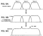
- the signal processing apparatus adds the plurality of video signals obtained by the high speed imaging to generates a standard speed video signals, but in this case, in the imaging apparatus, the video signals shown in FIG. 9A deform as shown in FIG. 9B due to the gamma processing and knee processing, so if combining these to generate a standard speed video signal, as shown in FIG. 9C , it suffers from the disadvantages that the standard speed video signal will suffer from unnatural edges or tones and the picture quality will become lower.
- EP 1014706 discloses a high-speed image pickup apparatus that obtains the same image quality as that of a standard-speed image pickup by simply converting a high-speed video signal into a plurality of standard-speed video signals.
- a video camera system comprises a video camera for outputting a video signal by picking up an object at a high speed.
- a transmitting path transmits the video signal to a signal processor.
- the signal processor signal-processes the transmitted video signal, and divides the high-speed video signal into a plurality of standard-speed video signals directly or by providing a blank field as an additional period by the video camera.
- the plurality of standard-speed video signals are transmitted by a transmitting path. By dividing a high-speed video signal into a plurality of channels of standard signals and signalprocessing them, a high-speed photographing video camera system can be formed simply.
- HDC-3300 HD Super Motion Color Camera discloses a device in the MAV-555 series that is MPEG based multi-channel editing disk recorder that combines advanced disk technology with a VTR-style of control proven in the day-to-day operation of broadcast operations.
- a video signal transfer system of a first aspect of the invention has an imaging apparatus for capturing an object to be imaged and generating a consecutive plurality of picture data forming a moving image, selecting from the plurality of picture data picture data positioned in advance at predetermined intervals to generate a plurality of lines (series) of video signals, and transmitting the plurality of lines of video signal, and a signal processing apparatus having a plurality of lines processing circuits, outputting the plurality of systems of video signals received from the imaging apparatus to the plurality of signal processing circuits, and making them process the signals in parallel.
- An imaging apparatus of a second aspect of the invention is an imaging apparatus transmitting imaging results to a signal processing apparatus having an imaging unit for capturing an object to be imaged and generating a consecutive plurality of picture data forming a moving image, a signal processing circuit for selecting from the plurality of picture data generated by the imaging unit the picture data positioned at predetermined intervals in advance to generate a plurality of lines (series) of video signals, and a transfer circuit for transmitting the plurality of lines of video signals generated by the signal processing circuit to the signal processing apparatus.
- a signal processing apparatus of a third aspect of the invention is a signal processing apparatus for processing a plurality of lines (series) of video signals received from an imaging apparatus capturing an object to be imaged to generate a consecutive plurality of picture data forming a moving image, selecting from the plurality of picture data the picture data positioned at predetermined intervals in advance to generate N ( ⁇ 2) lines (series) of video signals, having N number of signal processing circuits, a separating unit for outputting the N systems of video signals received from the imaging apparatus to the N number of signal processing circuits and making them process the signals in parallel, and an external apparatus outputting 1/N picture time's worth of picture data of the N number of video signals input from the N number of the signal processing circuits in one picture time.
- a video signal transfer method of a fourth aspect of the invention is a video signal transfer method transmitting imaging results of an imaging apparatus to a signal processing apparatus, having a first step of having the imaging apparatus configured to capture an object to be imaged and generate a consecutive plurality of picture data forming a moving image, a second step of having the imaging apparatus select from the plurality of picture data generated at the first step the picture data positioned at predetermined intervals in advance to generate a plurality of lines (series) of video signals and transmit the plurality of lines of video signals to the signal processing apparatus, and a third step of having the signal processing apparatus output the plurality of lines of video signals received from the imaging apparatus at the second step to the plurality of signal processing circuits and make them process the signals in parallel.
- a video signal transfer system enabling reduction of the amount of processing of the imaging apparatus when transferring a video signal generated by an imaging apparatus to a signal processing system.
- the present invention can provide a video signal transfer system, imaging apparatus, signal processing apparatus, and video signal transfer method able to suppress a drop in quality of the video signal output by the above signal processing apparatus.
- the video camera 10 is one example of an imaging apparatus of the present invention
- a camera control unit 12 is one example of a signal processing apparatus of the present invention.
- field pictures or frame pictures of the present embodiment are examples of the picture data of the present invention.
- video signals S34_1, S34_2, S34_3 of the present embodiment are examples of the plurality of lines (series) of video signals of the present invention.
- signal processing circuits 43_1, 43_2, 43_3 of the present embodiment are examples of the plurality of signal processing circuits of the present invention.
- the buffer memory 32 is an example of the memory of the present invention
- the viewfinder 33 is an example of the display of the present invention
- the signal processing circuit 34 is an example of the signal processing unit of the present invention.
- the preprocessing circuit 42 is an example of the separating unit of the present invention
- the addition circuit 71 is an example of the addition circuit of the present invention.
- FIG. 1 is a view of the overall configuration of a camera system 1 of the present embodiment.
- the camera system 1 has, for example, a video camera 10, camera control unit 12, and VTR or switcher (herein after VTR/switcher) 14.
- An external apparatus 20 is connected to the VTR/switcher 14.
- the video camera 10 generates a video signal in accordance with the imaging results and outputs it through an optical fiber cable 16 to the control unit 12.
- the camera control unit 12 processes the video signal inputted from the video camera 10 to generate an SDI (serial digital interface) type of video signal based on the SMPTE and outputs this through a cable 18 to the VTR/switcher 14.
- SDI serial digital interface
- the VTR/switcher 14 records or transmits the video signal inputted from the camera control unit 12.
- the optical fiber cable 16 for example, is a composite optical fiber cable made up of optical fiber for transmitting and receiving and metacables for power line and control use.
- the video camera 10 is arranged in a studio, and the camera control unit 12 and VTR/switcher 14 are arranged in a secondary adjustment room.
- this video signal and audio signal are outputted through the optical fiber cable 16 to the camera control unit 12 of the secondary adjustment room.
- the processed video signal and audio signal from the camera control unit 12 is outputted through the cable 18 to the VTR/switcher 14.
- VTR/switcher 14 performs signal processing for recording, editing, and transmitting the video signal and audio signal.
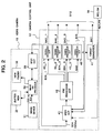
- FIG. 2 is a view of the configuration of the video camera 10 and the camera control unit 12.
- the video camera 10 as shown in FIG. 2 , has, for example, an imaging device 31, buffer memory 32, viewfinder 33, signal processing circuit 34, and transfer circuit 35.
- the imaging device 31 is, for example, a CMOS (Complementary Metal Oxide Semiconductor), CCD (Charge-Coupled Device), or other imaging device and outputs a video signal 31 in accordance with the imaging results to the signal processing circuit 34.
- CMOS Complementary Metal Oxide Semiconductor
- CCD Charge-Coupled Device
- the imaging device 31 for example, performs high speed imaging at 3X (three times worth) speed of the standard (normal) speed and generates an interlace format video signal S31.
- the imaging device 31 adjusted by a focusing mechanism. Further, the imaging results of the imaging device 31 are output as the video signal S31 after gain control.
- the buffer memory 32 stores the video signal processed in the signal processing circuit 34.
- the viewfinder 33 reads out and displays the video signal S31 stored in the buffer memory 32 under the control of the signal processing circuit 34.
- FIG. 3 is a view of the configuration of the signal processing circuit shown in FIG. 2 .
- the signal processing circuit 34 has, for example, an A/D conversion circuit 61, signal processing circuit 62, memory access circuit 63, and rearrangement circuit 64.
- the A/D conversion circuit 61 converts an analog video signal S31 inputted from the imaging device 31 to a digital video signal and outputs it to the signal processing circuit 62.
- the signal processing circuit 62 processes the digital video signal inputted from the A/D conversion circuit 61 relating to feedback control so as to generate the video signal S34a and outputs it to the memory access circuit 63.
- the memory access circuit 63 writes the video signal S34a in the buffer memory 32.
- the signal processing relating to the above feedback control includes gain control processing and auto alias level detection processing etc.
- the memory access circuit 63 writes the video signal S34a inputted from the signal processing circuit 62 in the buffer memory 32.
- the memory access circuit 63 reads out one of the fields for each consecutive 3 fields in the video signal S34a from the buffer memory 32 and outputs it to the viewfinder 33.
- the rearrangement circuit 64 receives as input the video signal S34a read by the memory access circuit 63 from the buffer memory 32.
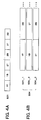
- the video signal S31 is of an interlace format, it rearranges the video signal S34a, as shown in FIG. 4 , so that the former 3 fields 1T, 1B, 2T of 6 fields forming one group match in time (become parallel) and outputs them as the video signal S34 to the transfer circuit 35.
- T indicates a top field
- B indicates a bottom field
- the rearrangement circuit 64 rearranges, after the above former 3 fields 1T, 1B, 2T, the latter 3 fields 2B, 3T, and 3B of the above 6 fields so as to match in time (become parallel) and outputs them as the video signal S34 to the transfer circuit 35.
- the rearrangement circuit 64 as shown in FIG. 4B , generates a video signal comprised of three lines (series) of video signals S34_1, S34_2, S34_3.
- the latter camera control unit 12 can realize the processing for adding the 3X speed captured field pictures and displaying of a standard speed image by a simple addition circuit.
- the transfer circuit 35 transmits the video signal S34 inputted from the rearrangement circuit 64 in parallel or by time division through the optical fiber cable 16 to the camera control unit 12.
- the transfer circuit 35 transmits one 10.692GHz video signal S34 comprised of R, G, B 12-bit signals mapped to a serial signal to the optical fiber cable 16.
- the transfer circuit 35 may transmit the video signal S34 as six 1.485GHz serial SDI signals through a BNC cable to the control unit 12.
- the 3X speed (three times worth speed to a normal speed) is an example.
- the present embodiment may also be applied to high speed transfer (NX (N times worth) speed transmission) other than 3X speed.
- the video camera 10 transmits the video signal S34 of the format shown in FIG. 4 to the camera control unit 12 regardless of the speed of the video signal S12 outputted by the camera control unit.
- the video signal is processed relating to feedback control, but Knee processing or gamma correction processing or other predetermined processing for improvement of quality, compression, etc. are not performed.
- the processing load of the video camera 10 can be reduced more than before.
- the camera control unit 12 has, as shown in FIG. 2 , a transfer circuit 41, preprocessing circuit 42, signal processing circuit 43_1, 43_2, 43_3, 45, and format conversion circuit 47.
- the transfer circuit 41 performs reverse format conversion from the transfer circuit 35 on the video signal S34 received through the optical fiber cable 16 from the video camera 10 and outputs the result to the preprocessing circuit 42.
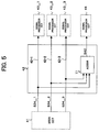
- FIG. 5 is a view of the configuration of the preprocessing circuit 42 as shown in FIG. 2 .
- the preprocessing circuit 42 outputs the video signals S34_1, S34_2, S34_3 forming the video signal S34 inputted from the transfer circuit 41 to the signal processing circuits 43_1, 43_2, 43_3.
- the preprocessing circuit 42 as shown in FIG. 5 , is provided with an addition circuit 71.
- the addition circuit 71 adds the video signals S34_1, S34_2, S34_3 forming the video signal S34 inputted from the transfer circuit 41 to generate the standard speed video signal S42 and outputs it to the signal processing circuit 45.
- the video signal S34 as shown in FIG. 4(B) , includes three lines (series) of video signals S34_1, S34_2, S34_3 stored in parallel, so there is no need to provide a memory for storing a large amounts of video signals before addition by the addition circuit 71.
- the signal processing circuits 43_1, 43_2, 43_3 process the video signals S34_1, S34_2, S34_3 for predetermined improvement of the quality, compression, etc. so as to generate the video signals S43_1, S43_2, S43 and outputs these as the video signal S12 to the VTR/switcher shown in FIG. 1 .
- the above signal processing performed by the signal processing circuits 43_1, 43_2, 43_3 include, for example, Knee processing (processing to compress multi-bits of pixel data to reduce load of color processing), gamma correction functions (processing to maximize input value to ideal output value in order to give vivid color), detail processing, etc.
- the signal processing circuits 43_1, 43_2, 43_3, for example, when reading out and replaying video signals stored in the VTR/switcher 14, perform processing to expand the read compressed video signals.
- the expanded video signals are outputted through the transfer circuit 41 to the video camera 10.
- the signal processing circuit 45 processes the standard speed video signal imputed from the preprocessing circuit 42 for predetermined improvement of quality, compression, etc. to generate the video signal S45 and outputs this as the video signal S12 to the VTR/switcher shown in FIG. 1 .
- the format conversion circuit 47 receives as input the video signal S45 from the signal processing circuit 45, converts it to a video signal 47 of a predetermined format, and outputs it as the video signal S12 to the VTR/switcher 14 shown in FIG. 1 .
- This conversion for example, is conversion that down converts an HD (High Definition) video signal to an SD (Standard Definition) video signal (NTSC system etc.).
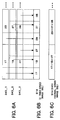
- the VTR/switcher 14 in the case of 3X speed video output, as shown in FIG. 6(B) , switches the video signals S43_1, S43_2, S43_3 inputted from the signal processing circuits 43_1, 43_2, 43_3 and outputs the 3X speed video signal S14.
- the switch 48 in the case of standard speed video output, as shown in FIG. 6(C) , outputs the video signal S45, obtained by adding the video signals S43_1, S43_2, S43_3 inputted from the signal processing circuit, as the standard speed video signal S14.
- the camera control unit 12 can output the 3X speed or standard speed video signal S14 by just processing for switching the video signals S14 inputted from the camera control unit 12.
- the VTR/switcher 14 for example, also has the function of writing the video signal S12 inputted from the camera control unit 12 on to a disk or other recording unit and rearranging it for output when reading it.
- the imaging device of the video camera 10 generates a video signal S31 in accordance with the imaging results of the imaging subject.
- the A/D conversion circuit 61 of the signal processing circuit 34 shown in FIG. 3 converts the video signal S31 to a digital format and writes the processed video signal S31a through the memory access circuit 63 in the buffer memory 32.
- the rearrangement circuit 64 receives as input the video signal S34a read from the buffer memory 32 through the memory access circuit 63.
- the video signal S31 is of an interlace format
- it rearranges the video signal S34a, as shown in FIG. 4 , so that the former 3 field pictures 1T, 1B, 2T of the 6 fields forming a group match in time (become parallel) and outputs them as the video signal S34 comprised of the three lines of standard speed video signals S34_1, S34_2, S34_3.
- the transfer circuit 35 transmits the video signal S34 inputted from the rearrangement circuit 64 in parallel or by time division through the optical fiber cable 16 to the camera control unit 12.
- the transfer circuit 41 of the camera control unit 12 performs reverse format conversion from the transfer circuit 35 on the video signal S34 received through the optical fiber cable 16 from the video camera 10 and outputs the result to the preprocessing circuit 42.
- the preprocessing circuit 42 of the camera control unit 12 outputs the video signals S34_1, S34_2, S34_3 forming the video signal S34 inputted from the transfer circuit 41 to the signal processing circuits 43_1, 43_2, 43_3.
- the addition circuit 71 adds the video signals S34_1, S34_2, S34_3 forming the video signal S34 inputted from the transfer circuit to generate the standard speed video signal S42 and outputs it to the signal processing circuit 45.
- the signal processing circuits 43_1, 43_2, 43_3 process the video signals S34_1, S34_2, S34_3 for predetermined improvement of quality, compression, etc. to generate the video signals S43_1, S43_2, S43_3 and outputs them as the video signal S12 to the VTR/switcher 14.
- the signal processing circuit 45 has processes the standard speed video signal inputted from the preprocessing circuit 42 for predetermined improvement of quality, compression, etc. to generate the video signal S45 and outputs it as the video signal S12 to the VTR/switcher 14.
- the VTR/switcher 14 in the case of 3X speed video output, as shown in FIG. 6B , switches from the video signals S43_1, S43_2, S43_3 inputted from the signal processing circuits 43_1, 43_2, 43_3 and outputs the 3X speed video signal S_14.
- the VTR/switcher 14 in the case of standard speed video output, as shown in FIG. 6C , outputs the video signal S45, obtained by adding the video signals S43_1, S43_2, S43_3 inputted from the signal processing circuit, as the standard speed video signal S14.
- the rearrangement circuit 64 of the video camera 10 shown in FIG. 3 generates three systems of 1X speed video signals S34_1, S34_2, S34_3 from the video signal S31 captured at 3X speed shown in FIG. 4A and transmits it to the camera control unit 12 in accordance with their timings.
- the camera control unit 12 performs parallel processing on the video signals S34_1, S34_2, S34_3 received from the video camera 10 at the signal processing circuits 43_1, 43_2, 43_3 shown in FIG. 2 .
- the camera control unit 12 can process a video signal captured at 3X speed in a short time.
- the signal processing circuit 62 of the video camera 10 shown in FIG. 3 processes the digital video signal inputted from the A/D conversion circuit 61 for gain control, auto alias level detection, or other feedback control.
- the signal processing circuits 43_1, 43_2, 43_3 of the camera control unit 12 process the video signals S34_1, S34_2, S34_3 for Knee processing, gamma correction, or other predetermined improvement of quality, compression, etc.
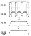
- the addition circuit 71 of the preprocessing circuit 42 shown in FIG. 5 adds the three systems of video signals to generate a standard speed video signal, as shown in FIGS. 7B and 7C , it can add them in a state without image processing and can therefore avoid a drop in quality as explained with reference to FIG. 9 .
- the image processing for improvement of quality is not performed by the video camera 10, but by the camera control unit 12, so the amount of processing and power consumption of the video camera 10 can be reduced.
- This effect is particularly remarkable in the case of using, as a video signal, an HD signal with several times larger an amount of data than SD.
- the video camera 10 temporarily stores the picture data generated at the imaging device 31 in the buffer memory 32, then reads it out and displays the image on the viewfinder 33. For this reason, even when no communication link is established between the video camera 10 and the camera control unit 12, it is still possible to display a captured image on the viewfinder 33. Due to this, the system setup can be made more efficient.
- the viewfinder 33 can display an image with almost no delay and can track and display an image of an object moving at a high speed.
- the video camera 10 In the camera system 1, the video camera 10 generates three lines of standard speed video signals S34_1, S34_2, S34_3 from the high speed captured video signal S31 and transmits them to the camera control unit 12. Further, the camera control unit 12 processes the three lines of standard speed video signals S34_1, S34_2, S34_3 at the signal processing circuits 43_1, 43_2, 43_3 in parallel, then switches and outputs the results so as to output a 3X speed video signal.
- the video signals S34_1, S34_2, S34_3 can be constantly processed at standard speed, and the circuit configuration can be made simple and inexpensive.
- the video camera 10 generates three lines of standard speed video signals S34_1, S34_2, S34_3, so the camera control unit 12 does not need to be provided with a large scale memory.
- the effect is particularly remarkable in cases where, as the video signal, an HD image with several times the amount of data compared with the SD is used.
- common signal processing circuits can be used as the signal processing circuits 43_1, 43_2, 43_3, so even if the image capture speed is increased to 3X (three times) or more, this can be handled by just increasing the same signal processing circuits.
- the video signal transmitted from the video camera 10 to the camera control unit 12 is not compressed, so high quality video output is possible.
- a standard speed video signal is generated by addition before camera signal processing by the signal processing circuit 45, so it is possible to output high quality video as standard speed video.
- the standard speed video is high quality, usage as a standard speed imaging camera and not just as a high speed imaging camera is possible.
- high speed video and standard speed video can be outputted at the same time, so it is possible to combine the two separate lines required for high speed imaging and standard speed imaging into one.
- the types of signals that can be taken by the camera are increased and flexible application as a system is possible.
- the processed signal to be displayed on the viewfinder 33 may be selected from one with an added natural dynamic resolution feel or a high speed video with a shutter effect, so the optimal video (picture) can be displayed on the viewfinder 33 in accordance with the objective.
- the video signal returning from the camera control unit 12 to the video camera 10 for display on the viewfinder 33 may be selected from one system of processed high speed output with a shutter effect or added standard speed video with natural motion.
- the imaging device 31 generated a video signal 31a of an interlaced format, however, in the present embodiment, as shown in FIG. 8A , the imaging device 31a generates a video signal S31a of a progressive format.
- the rearrangement circuit 64 assigns consecutive frames (for example, “1”, “2”, “3") in groups of three frames to the plurality of different video signals S34_1a, S34_2a, S34_3a.
- the present invention is not limited to the above embodiments.
Landscapes
- Engineering & Computer Science (AREA)
- Multimedia (AREA)
- Signal Processing (AREA)
- Computing Systems (AREA)
- Theoretical Computer Science (AREA)
- Studio Devices (AREA)
- Color Television Image Signal Generators (AREA)
Claims (12)
- Système de transfert de signaux vidéo, comprenant :un appareil d'imagerie (10) pour capturer un objet (OB) à imager et générer une pluralité de données d'image consécutives formant une image animée, pour sélectionner parmi la pluralité de données d'image des données d'image situées à des intervalles de temps prédéfinis afin de générer N (N ≥ 2) signaux vidéo, lequel appareil d'imagerie comprend un circuit de transfert pour transmettre la pluralité de signaux vidéo à une unité dé commande de caméra (12) par un câble à fibres optiques (16), etl'unité de commande de caméra (12) comprenant N circuits de traitement de signaux (43-1, 43-2, ..., 45), l'unité de commande de caméra (12) comprenant un circuit de transfert (41) conçu pour recevoir la pluralité de signaux vidéo en provenance de l'appareil d'imagerie (10) et conçu pour faire en sorte que la pluralité de circuits de traitement de signaux traitent les signaux vidéo en parallèle,laquelle unité de commande de caméra (12) comprend une unité de séparation (42) conçue pour fournir chacun de la pluralité de signaux vidéo reçus en provenance de l'appareil d'imagerie (10) à chacun des circuits de traitement de signaux, les circuits de traitement de signaux étant conçus pour traiter la pluralité de signaux vidéo reçus en provenance de l'appareil d'imagerie pour obtenir une amélioration de qualité prédéfinie,caractérisé en ce quel'unité de séparation (42) comprend en outre une unité d'addition (71) conçue pour recevoir en parallèle et ajouter la pluralité de signaux vidéo séparés par l'unité de séparation (42) de manière à générer un nouveau signall'unité de commande de caméra (12) comprend un circuit de traitement de signaux supplémentaire (45) pour effectuer un traitement du type coude, etl'unité d'addition (71) est conçue pour fournir le nouveau signal vidéo à vitesse normale au circuit de traitement de signaux supplémentaire (45), lequel est conçu pour traiter le nouveau signal vidéo à vitesse normale pour obtenir une amélioration de qualité prédéfinie et pour fournir le nouveau signal vidéo à vitesse normale traité (S45).
- Système de transfert de signaux vidéo selon la revendication 1, dans lequel
l'appareil d'imagerie (10) est conçu pour effectuer un traitement du type rétroaction, notamment un traitement du type commande de gain et/ou un traitement du type détection automatique de niveau de crénelage, l'appareil d'imagerie (10) étant conçu pour générer l'image animée sur la base des données d'image, et
la pluralité de circuits de traitement de signaux (43-1, 43-2, ..., 45) de l'unité de commande de caméra (12) est conçue pour traiter la pluralité de signaux vidéo (43-1, 43-2, ..., 45) pour comprimer ou développer des données. - Système de transfert de signaux vidéo selon la revendication 1, dans lequel l'appareil d'imagerie (10) comprend :une unité d'imagerie (31) conçue pour générer la pluralité de données d'image,une unité de traitement (34) conçue pour traiter la pluralité de données d'image et régler l'unité d'imagerie sur la base de la pluralité de données d'image générées par l'unité d'imagerie, etune unité de réagencement (64) conçue pour générer la pluralité de signaux vidéo.
- Système de transfert de signaux vidéo selon la revendication 1, dans lequel
la pluralité de signaux vidéo générés par l'appareil d'imagerie (10) sont au nombre de N, N ≥ 2,
l'appareil d'imagerie (10) est conçu pour mémoriser un nombre N de données d'image consécutives formant l'image animée, pour commander le nombre N de données d'image consécutives de façon à les transmettre en même temps, et pour transmettre la pluralité de signaux vidéo à une vitesse de 1/N la vitesse de capture de l'image animée. - Système de transfert de signaux vidéo selon la revendication 1, dans lequel l'appareil d'imagerie (10) comprend
une mémoire (32) pour mémoriser la pluralité de données d'image consécutives générées,
un affichage (34) pour afficher une image formée en fonction de la pluralité de données d'image consécutives mémorisées dans la mémoire, et
une unité de réagencement (64) conçue pour sélectionner parmi la pluralité de données d'image consécutives formant l'image animée lues dans la mémoire les données d'image situées à des intervalles de temps prédéfinis de manière à générer une pluralité de signaux vidéo, et pour générer la pluralité de signaux vidéo. - Système de transfert de signaux vidéo selon la revendication 1, dans lequel
l'appareil d'imagerie (10) est conçu pour générer N (N ≥ 2) signaux vidéo, pour mémoriser un nombre N de données d'image consécutives formant l'image animée, pour commander le nombre N de données d'image consécutives de façon à les transmettre sensiblement en même temps, et pour transmettre la pluralité de signaux vidéo à une vitesse de 1/N la vitesse de capture d'image par l'appareil d'imagerie (10), et
l'unité de commande de caméra (12) est conçue pour fournir les signaux vidéo traités en provenance du nombre N de circuits de traitement de signaux à un appareil externe (20), et
l'appareil externe (20) est conçu pour fournir l'équivalent de 1/N temps d'image de données d'image de l'un du nombre N de signaux vidéo appliqués en entrée dans un temps d'image. - Système de transfert de signaux vidéo selon la revendication 6, dans lequel
l'appareil externe (20) est conçu pour sélectionner et pour fournir l'une des sorties du nombre N de circuits de traitement de signaux (43-1, ..., 43-3, 45) à une vitesse de 1/N la vitesse de capture d'image par l'appareil d'imagerie (10). - Système de transfert de signaux vidéo selon la revendication 1, dans lequel
l'appareil d'imagerie (10) comprend une unité de traitement de signaux (34) conçue pour générer N (N ≥ 2) signaux vidéo, pour mémoriser un nombre N (N ≥ 2) de données d'image consécutives formant chaque fois l'image animée dans une ligne différente du signal vidéo, pour commander le nombre N de données d'image consécutives de façon à les transmettre sensiblement en même temps, et pour transmettre la pluralité de signaux vidéo à une vitesse de 1/N la vitesse de capture d'image. - Système de transfert de signaux vidéo selon la revendication 8, dans lequel l'unité de traitement de signaux (34) comprend :un circuit de réagencement d'image (64) conçu pour séparer un signal d'image traité à X fois la vitesse comportant une pluralité de données d'image en une pluralité de signaux d'image à une fois la vitesse et pour réagencer la pluralité de signaux d'image séparés à une fois la vitesse de façon à les faire coïncider dans le temps.
- Système de transfert de signaux vidéo selon la revendication 9, dans lequel l'unité de traitement de signaux (34) comporte
un circuit d'accès en mémoire (63) pour enregistrer le signal d'image dans une mémoire tampon (32) comportant la pluralité de données d'image traitées par l'unité de traitement de signaux,
lequel circuit de réagencement d'image (64) est conçu pour recevoir un signal d'image prédéfini à X fois la vitesse dans la mémoire tampon (32). - Unité de commande de caméra (12) pour traiter une pluralité de signaux vidéo reçus en provenance d'un appareil d'imagerie (10), l'appareil d'imagerie (10) capturant un objet (OB) à imager afin de générer une pluralité de données d'image consécutives formant une image animée, pour sélectionner parmi la pluralité de données d'image des données d'image situées à des intervalles de temps prédéfinis afin de générer N (N ≥ 2) signaux vidéo, l'unité de commande de caméra (12) comprenant un circuit de transfert pour recevoir la pluralité de signaux vidéo par un câble à fibres optiques (16), un nombre N de circuits de traitement de signaux (43-1, 43-2, ..., 45),
une unité de séparation (42) étant conçue pour fournir les N signaux vidéo reçus en provenance de l'appareil d'imagerie (10) au nombre N de circuits de traitement de signaux et faire en sorte qu'ils traitent les signaux en parallèle, et
l'unité de commande de caméra (12) étant conçue pour transmettre les signaux vidéo à un appareil externe (20) pour fournir l'équivalent de 1/N temps d'image de données d'image d'un signal vidéo donné du nombre N de signaux vidéo appliqués en entrée depuis le nombre N de circuits de traitement de signaux dans un temps d'image,
laquelle unité de commande de caméra (12) comprend :l'unité de séparation (42) conçue pour fournir chacun de la pluralité de signaux vidéo reçus en provenance de l'appareil d'imagerie (10) à l'un des circuits de traitement de signaux chacun, les circuits de traitement de signaux étant conçus pour traiter la pluralité de signaux vidéo reçus en provenance de l'appareil d'imagerie pour obtenir une amélioration de qualité prédéfinie,caractérisée en ce quel'unité de séparation (42) comprend en outre une unité d'addition (71) conçue pour recevoir en parallèle et ajouter la pluralité de signaux vidéo séparés par l'unité de séparation (42) de manière à générer un nouveau signal vidéo à vitesse normale, etl'unité de commande de caméra (12) comprend un circuit de traitement de signaux supplémentaire (45) pour effectuer un traitement du type coude, etl'unité d'addition (71) est conçue pour fournir le nouveau signal vidéo à vitesse normale au circuit de traitement de signaux supplémentaire (45), lequel est conçu pour traiter le nouveau signal vidéo à vitesse normale pour obtenir une amélioration de qualité prédéfinie et pour fournir le nouveau signal vidéo à vitesse normale traité (S45). - Procédé de transfert de signaux vidéo pour transmettre des résultats d'imagerie d'un appareil d'imagerie (10) à une unité de commande de caméra (12) comportant N (N ≥ 2) circuits de traitement de signaux (43-1, 43-2, ..., 45), le procédé comprenant :une première étape consistant à faire en sorte que l'appareil d'imagerie (10) soit configuré pour capturer un objet (OB) à imager et générer une pluralité de données d'image consécutives formant une image animée,une deuxième étape consistant à faire en sorte que l'appareil d'imagerie (10) sélectionne parmi la pluralité de données d'image générées à la première étape les données d'image situées à des intervalles de temps prédéfinis afin de générer N signaux vidéo, et transmette la pluralité de signaux vidéo à l'unité de commande de caméra (12) par un câble à fibres optiques (16), etune troisième étape consistant à recevoir la pluralité de signaux vidéo et à faire en sorte que l'unité de commande de caméra (12) fournisse la pluralité de signaux vidéo reçus en provenance de l'appareil d'imagerie (10) à la deuxième étape à la pluralité de circuits de traitement de signaux (43-1, 43-2, ..., 45) et fasse en sorte qu'ils traitent les signaux en parallèle, etlequel procédé de transfert comprend l'étape consistant àfournir chacun de la pluralité de signaux vidéo reçus en provenance de l'appareil d'imagerie (10) à l'un des circuits de traitement de signaux chacun, les circuits de traitement de signaux étant conçus pour traiter la pluralité de signaux vidéo reçus en provenance de l'appareil d'imagerie pour obtenir une amélioration de qualité prédéfinie,caractérisé en ce qu'il comprend l'étape consistant àrecevoir en parallèle et ajouter la pluralité de signaux vidéo séparés par l'unité de séparation (42) de manière à générer un nouveau signal vidéo à vitesse normale, etet en ce qu'il comprend les étapes consistant àfournir le nouveau signal vidéo à vitesse normale par une unité d'addition (71) à un circuit de traitement de signaux supplémentaire (45) et traiter le nouveau signal vidéo à vitesse normale par le circuit de traitement de signaux supplémentaire (48) pour effectuer un traitement du type coude, etfournir le nouveau signal vidéo à vitesse normale traité (S45).
Applications Claiming Priority (2)
| Application Number | Priority Date | Filing Date | Title |
|---|---|---|---|
| JP2005261066 | 2005-09-08 | ||
| JP2005330533A JP4475225B2 (ja) | 2005-09-08 | 2005-11-15 | 映像信号伝送システム、撮像装置、信号処理装置および映像信号伝送方法 |
Publications (3)
| Publication Number | Publication Date |
|---|---|
| EP1763224A2 EP1763224A2 (fr) | 2007-03-14 |
| EP1763224A3 EP1763224A3 (fr) | 2011-08-31 |
| EP1763224B1 true EP1763224B1 (fr) | 2013-11-27 |
Family
ID=37527051
Family Applications (1)
| Application Number | Title | Priority Date | Filing Date |
|---|---|---|---|
| EP06018361.3A Ceased EP1763224B1 (fr) | 2005-09-08 | 2006-09-01 | Traitement de signal vidéo dans une unité de contrôle de caméra |
Country Status (4)
| Country | Link |
|---|---|
| US (2) | US8125532B2 (fr) |
| EP (1) | EP1763224B1 (fr) |
| JP (1) | JP4475225B2 (fr) |
| TW (1) | TWI386038B (fr) |
Families Citing this family (9)
| Publication number | Priority date | Publication date | Assignee | Title |
|---|---|---|---|---|
| US20080266444A1 (en) * | 2007-04-27 | 2008-10-30 | Micron Technology, Inc. | Method, apparatus, and system for continuous autofocusing |
| JP5088395B2 (ja) * | 2010-04-15 | 2012-12-05 | 株式会社ニコン | 電子カメラ |
| JP2013031143A (ja) | 2011-04-08 | 2013-02-07 | Sony Corp | 映像処理装置及び映像処理方法 |
| KR101316231B1 (ko) * | 2011-07-26 | 2013-10-08 | 엘지이노텍 주식회사 | 다중 영상 처리 장치 |
| GB2516288B (en) * | 2013-07-18 | 2015-04-08 | Imagination Tech Ltd | Image processing system |
| US9496922B2 (en) | 2014-04-21 | 2016-11-15 | Sony Corporation | Presentation of content on companion display device based on content presented on primary display device |
| CN105187735A (zh) * | 2015-07-23 | 2015-12-23 | 柳州永旺科技有限公司 | 一种多路动态图像的合成方法 |
| CN113475054A (zh) * | 2019-02-27 | 2021-10-01 | 富士胶片株式会社 | 摄像装置、摄像装置的图像数据处理方法及程序 |
| CN121002891A (zh) * | 2023-04-04 | 2025-11-21 | 索尼集团公司 | 成像设备、成像信号处理设备和成像系统 |
Citations (1)
| Publication number | Priority date | Publication date | Assignee | Title |
|---|---|---|---|---|
| JPH1023318A (ja) * | 1996-07-09 | 1998-01-23 | Matsushita Electric Ind Co Ltd | 高速度カメラシステム |
Family Cites Families (16)
| Publication number | Priority date | Publication date | Assignee | Title |
|---|---|---|---|---|
| JP3560622B2 (ja) * | 1992-04-30 | 2004-09-02 | オリンパス株式会社 | 撮像装置 |
| JP2000050205A (ja) | 1998-07-24 | 2000-02-18 | Sony Corp | 撮像システム |
| JP2967483B1 (ja) * | 1998-07-27 | 1999-10-25 | 大同電機工業株式会社 | 検出対象物抽出処理装置 |
| JP4178634B2 (ja) * | 1998-12-22 | 2008-11-12 | ソニー株式会社 | 映像信号伝送装置、映像信号伝送方法、映像信号撮像装置および映像信号処理装置 |
| JP3700488B2 (ja) * | 1999-09-06 | 2005-09-28 | 日本ビクター株式会社 | 広角画像撮像装置 |
| JP2002247593A (ja) * | 2001-02-16 | 2002-08-30 | Olympus Optical Co Ltd | 画像処理装置 |
| JP3877565B2 (ja) * | 2001-10-04 | 2007-02-07 | 松下電器産業株式会社 | 撮像装置 |
| WO2003063471A1 (fr) * | 2002-01-22 | 2003-07-31 | Sony Corporation | Dispositif d'imagerie et technique afferente |
| US6894726B2 (en) * | 2002-07-05 | 2005-05-17 | Thomson Licensing S.A. | High-definition de-interlacing and frame doubling circuit and method |
| US7460156B2 (en) * | 2003-03-19 | 2008-12-02 | Hitachi, Ltd. | Signal transmission method between television camera and video apparatus and apparatus using the method |
| JP2004289631A (ja) * | 2003-03-24 | 2004-10-14 | Fuji Photo Film Co Ltd | デジタルカメラ |
| JP3731589B2 (ja) * | 2003-07-18 | 2006-01-05 | ソニー株式会社 | 撮像装置と同期信号発生装置 |
| JP4160522B2 (ja) | 2004-03-11 | 2008-10-01 | リンナイ株式会社 | 電動弁装置 |
| JP2005330533A (ja) | 2004-05-19 | 2005-12-02 | Fujikura Ltd | 多結晶配向中間薄膜とその製造方法及び酸化物超電導導体とその製造方法 |
| US7492821B2 (en) * | 2005-02-08 | 2009-02-17 | International Business Machines Corporation | System and method for selective image capture, transmission and reconstruction |
| JP2007201985A (ja) * | 2006-01-30 | 2007-08-09 | Matsushita Electric Ind Co Ltd | 広ダイナミックレンジ撮像装置 |
-
2005
- 2005-11-15 JP JP2005330533A patent/JP4475225B2/ja not_active Expired - Lifetime
-
2006
- 2006-07-28 TW TW095127607A patent/TWI386038B/zh not_active IP Right Cessation
- 2006-08-02 US US11/461,882 patent/US8125532B2/en not_active Expired - Fee Related
- 2006-09-01 EP EP06018361.3A patent/EP1763224B1/fr not_active Ceased
-
2012
- 2012-02-03 US US13/366,027 patent/US8564685B2/en active Active
Patent Citations (1)
| Publication number | Priority date | Publication date | Assignee | Title |
|---|---|---|---|---|
| JPH1023318A (ja) * | 1996-07-09 | 1998-01-23 | Matsushita Electric Ind Co Ltd | 高速度カメラシステム |
Also Published As
| Publication number | Publication date |
|---|---|
| TWI386038B (zh) | 2013-02-11 |
| US20120133792A1 (en) | 2012-05-31 |
| EP1763224A2 (fr) | 2007-03-14 |
| EP1763224A3 (fr) | 2011-08-31 |
| TW200721807A (en) | 2007-06-01 |
| JP2007104623A (ja) | 2007-04-19 |
| JP4475225B2 (ja) | 2010-06-09 |
| US20070053664A1 (en) | 2007-03-08 |
| US8125532B2 (en) | 2012-02-28 |
| US8564685B2 (en) | 2013-10-22 |
Similar Documents
| Publication | Publication Date | Title |
|---|---|---|
| US8564685B2 (en) | Video signal capturing apparatus, signal processing and control apparatus, and video signal capturing, video signal processing, and transferring system and method | |
| JP5036410B2 (ja) | 撮像装置及びその制御方法 | |
| KR100666290B1 (ko) | 촬상 장치 및 촬상 방법 | |
| EP0762747B1 (fr) | Appareil de prise d'images avec dispositif de prise d'images à balayage non-entrelacé ou progressif | |
| JPH10210367A (ja) | 電子的撮像装置 | |
| US6710802B2 (en) | Image recording apparatus and image reproducing apparatus | |
| US7432958B2 (en) | Image pickup apparatus with function of adjusting incident light quantity | |
| KR20100094401A (ko) | 동영상을 기록하는 기록 장치, 기록 방법 및 컴퓨터로 판독 가능한 기록 매체 | |
| JP2000188703A (ja) | 映像信号伝送装置、映像信号伝送方法、映像信号撮像装置および映像信号処理装置 | |
| US20010024234A1 (en) | Digital camera | |
| JP2620433B2 (ja) | 画像処理のためのフィールド補間回路及び方法 | |
| US7236194B2 (en) | Image signal processing apparatus | |
| JP2000125213A (ja) | 固体撮像装置 | |
| US7940308B2 (en) | Image processing system, image pickup apparatus, image pickup method, image reproducing apparatus, and image reproducing method | |
| US6020922A (en) | Vertical line multiplication method for high-resolution camera and circuit therefor | |
| JP2001230955A (ja) | 撮像装置及び撮像システム | |
| CN100518247C (zh) | 视频信号拍摄、处理及传送的系统、方法和设备 | |
| JP2009038627A (ja) | 撮像装置 | |
| JPH0983873A (ja) | 撮像装置 | |
| KR100754223B1 (ko) | 영상 처리 장치 및 방법 | |
| JP2013211644A (ja) | 画像処理装置 | |
| EP0989746A2 (fr) | Appareil de prise de vue ayant une fonction de prise de vue à grande vitesse avec circuit de zoom électronique | |
| JP3768987B2 (ja) | 撮像装置 | |
| JPH04170176A (ja) | 固体撮像装置 | |
| JPH04323971A (ja) | ビデオカメラ装置 |
Legal Events
| Date | Code | Title | Description |
|---|---|---|---|
| PUAI | Public reference made under article 153(3) epc to a published international application that has entered the european phase |
Free format text: ORIGINAL CODE: 0009012 |
|
| AK | Designated contracting states |
Kind code of ref document: A2 Designated state(s): AT BE BG CH CY CZ DE DK EE ES FI FR GB GR HU IE IS IT LI LT LU LV MC NL PL PT RO SE SI SK TR |
|
| AX | Request for extension of the european patent |
Extension state: AL BA HR MK YU |
|
| PUAL | Search report despatched |
Free format text: ORIGINAL CODE: 0009013 |
|
| AK | Designated contracting states |
Kind code of ref document: A3 Designated state(s): AT BE BG CH CY CZ DE DK EE ES FI FR GB GR HU IE IS IT LI LT LU LV MC NL PL PT RO SE SI SK TR |
|
| AX | Request for extension of the european patent |
Extension state: AL BA HR MK RS |
|
| RIC1 | Information provided on ipc code assigned before grant |
Ipc: H04N 5/232 20060101AFI20110722BHEP |
|
| 17P | Request for examination filed |
Effective date: 20120222 |
|
| 17Q | First examination report despatched |
Effective date: 20120330 |
|
| AKX | Designation fees paid |
Designated state(s): DE FR GB |
|
| GRAP | Despatch of communication of intention to grant a patent |
Free format text: ORIGINAL CODE: EPIDOSNIGR1 |
|
| INTG | Intention to grant announced |
Effective date: 20130618 |
|
| GRAS | Grant fee paid |
Free format text: ORIGINAL CODE: EPIDOSNIGR3 |
|
| GRAA | (expected) grant |
Free format text: ORIGINAL CODE: 0009210 |
|
| AK | Designated contracting states |
Kind code of ref document: B1 Designated state(s): DE FR GB |
|
| REG | Reference to a national code |
Ref country code: GB Ref legal event code: FG4D |
|
| REG | Reference to a national code |
Ref country code: DE Ref legal event code: R096 Ref document number: 602006039403 Country of ref document: DE Effective date: 20140123 |
|
| REG | Reference to a national code |
Ref country code: DE Ref legal event code: R097 Ref document number: 602006039403 Country of ref document: DE |
|
| PLBE | No opposition filed within time limit |
Free format text: ORIGINAL CODE: 0009261 |
|
| STAA | Information on the status of an ep patent application or granted ep patent |
Free format text: STATUS: NO OPPOSITION FILED WITHIN TIME LIMIT |
|
| 26N | No opposition filed |
Effective date: 20140828 |
|
| REG | Reference to a national code |
Ref country code: DE Ref legal event code: R097 Ref document number: 602006039403 Country of ref document: DE Effective date: 20140828 |
|
| REG | Reference to a national code |
Ref country code: DE Ref legal event code: R084 Ref document number: 602006039403 Country of ref document: DE |
|
| REG | Reference to a national code |
Ref country code: GB Ref legal event code: 746 Effective date: 20150421 |
|
| REG | Reference to a national code |
Ref country code: DE Ref legal event code: R084 Ref document number: 602006039403 Country of ref document: DE Effective date: 20150410 |
|
| REG | Reference to a national code |
Ref country code: FR Ref legal event code: PLFP Year of fee payment: 10 |
|
| REG | Reference to a national code |
Ref country code: FR Ref legal event code: PLFP Year of fee payment: 11 |
|
| REG | Reference to a national code |
Ref country code: FR Ref legal event code: PLFP Year of fee payment: 12 |
|
| REG | Reference to a national code |
Ref country code: FR Ref legal event code: PLFP Year of fee payment: 13 |
|
| PGFP | Annual fee paid to national office [announced via postgrant information from national office to epo] |
Ref country code: GB Payment date: 20200921 Year of fee payment: 15 Ref country code: FR Payment date: 20200914 Year of fee payment: 15 |
|
| PGFP | Annual fee paid to national office [announced via postgrant information from national office to epo] |
Ref country code: DE Payment date: 20210818 Year of fee payment: 16 |
|
| GBPC | Gb: european patent ceased through non-payment of renewal fee |
Effective date: 20210901 |
|
| PG25 | Lapsed in a contracting state [announced via postgrant information from national office to epo] |
Ref country code: GB Free format text: LAPSE BECAUSE OF NON-PAYMENT OF DUE FEES Effective date: 20210901 Ref country code: FR Free format text: LAPSE BECAUSE OF NON-PAYMENT OF DUE FEES Effective date: 20210930 |
|
| REG | Reference to a national code |
Ref country code: DE Ref legal event code: R079 Ref document number: 602006039403 Country of ref document: DE Free format text: PREVIOUS MAIN CLASS: H04N0005232000 Ipc: H04N0023600000 |
|
| REG | Reference to a national code |
Ref country code: DE Ref legal event code: R119 Ref document number: 602006039403 Country of ref document: DE |
|
| PG25 | Lapsed in a contracting state [announced via postgrant information from national office to epo] |
Ref country code: DE Free format text: LAPSE BECAUSE OF NON-PAYMENT OF DUE FEES Effective date: 20230401 |