EP1763377B1 - Pince pour catheter - Google Patents
Pince pour catheter Download PDFInfo
- Publication number
- EP1763377B1 EP1763377B1 EP05761165A EP05761165A EP1763377B1 EP 1763377 B1 EP1763377 B1 EP 1763377B1 EP 05761165 A EP05761165 A EP 05761165A EP 05761165 A EP05761165 A EP 05761165A EP 1763377 B1 EP1763377 B1 EP 1763377B1
- Authority
- EP
- European Patent Office
- Prior art keywords
- grip
- catheter
- separators
- members
- grip members
- Prior art date
- Legal status (The legal status is an assumption and is not a legal conclusion. Google has not performed a legal analysis and makes no representation as to the accuracy of the status listed.)
- Ceased
Links
- 210000003462 vein Anatomy 0.000 description 4
- 230000001939 inductive effect Effects 0.000 description 3
- 238000002679 ablation Methods 0.000 description 2
- 210000001367 artery Anatomy 0.000 description 2
- 230000000694 effects Effects 0.000 description 2
- 238000011156 evaluation Methods 0.000 description 2
- 238000013507 mapping Methods 0.000 description 2
- 239000000463 material Substances 0.000 description 2
- 244000043261 Hevea brasiliensis Species 0.000 description 1
- 229910000831 Steel Inorganic materials 0.000 description 1
- 230000001594 aberrant effect Effects 0.000 description 1
- 230000001154 acute effect Effects 0.000 description 1
- 238000013459 approach Methods 0.000 description 1
- 230000017531 blood circulation Effects 0.000 description 1
- 210000005242 cardiac chamber Anatomy 0.000 description 1
- 230000000295 complement effect Effects 0.000 description 1
- 230000006835 compression Effects 0.000 description 1
- 238000007906 compression Methods 0.000 description 1
- 238000007796 conventional method Methods 0.000 description 1
- 230000008878 coupling Effects 0.000 description 1
- 238000010168 coupling process Methods 0.000 description 1
- 238000005859 coupling reaction Methods 0.000 description 1
- 230000007423 decrease Effects 0.000 description 1
- 210000001105 femoral artery Anatomy 0.000 description 1
- 239000012530 fluid Substances 0.000 description 1
- 238000000034 method Methods 0.000 description 1
- 229920003052 natural elastomer Polymers 0.000 description 1
- 229920001194 natural rubber Polymers 0.000 description 1
- 238000000926 separation method Methods 0.000 description 1
- 239000010959 steel Substances 0.000 description 1
- 229920003051 synthetic elastomer Polymers 0.000 description 1
- 238000013519 translation Methods 0.000 description 1
Images


Classifications
-
- A—HUMAN NECESSITIES
- A61—MEDICAL OR VETERINARY SCIENCE; HYGIENE
- A61M—DEVICES FOR INTRODUCING MEDIA INTO, OR ONTO, THE BODY; DEVICES FOR TRANSDUCING BODY MEDIA OR FOR TAKING MEDIA FROM THE BODY; DEVICES FOR PRODUCING OR ENDING SLEEP OR STUPOR
- A61M25/00—Catheters; Hollow probes
- A61M25/01—Introducing, guiding, advancing, emplacing or holding catheters
- A61M25/02—Holding devices, e.g. on the body
-
- A—HUMAN NECESSITIES
- A61—MEDICAL OR VETERINARY SCIENCE; HYGIENE
- A61M—DEVICES FOR INTRODUCING MEDIA INTO, OR ONTO, THE BODY; DEVICES FOR TRANSDUCING BODY MEDIA OR FOR TAKING MEDIA FROM THE BODY; DEVICES FOR PRODUCING OR ENDING SLEEP OR STUPOR
- A61M25/00—Catheters; Hollow probes
- A61M25/0097—Catheters; Hollow probes characterised by the hub
-
- A—HUMAN NECESSITIES
- A61—MEDICAL OR VETERINARY SCIENCE; HYGIENE
- A61M—DEVICES FOR INTRODUCING MEDIA INTO, OR ONTO, THE BODY; DEVICES FOR TRANSDUCING BODY MEDIA OR FOR TAKING MEDIA FROM THE BODY; DEVICES FOR PRODUCING OR ENDING SLEEP OR STUPOR
- A61M25/00—Catheters; Hollow probes
- A61M25/01—Introducing, guiding, advancing, emplacing or holding catheters
- A61M25/06—Body-piercing guide needles or the like
- A61M25/0612—Devices for protecting the needle; Devices to help insertion of the needle, e.g. wings or holders
-
- A—HUMAN NECESSITIES
- A61—MEDICAL OR VETERINARY SCIENCE; HYGIENE
- A61M—DEVICES FOR INTRODUCING MEDIA INTO, OR ONTO, THE BODY; DEVICES FOR TRANSDUCING BODY MEDIA OR FOR TAKING MEDIA FROM THE BODY; DEVICES FOR PRODUCING OR ENDING SLEEP OR STUPOR
- A61M25/00—Catheters; Hollow probes
- A61M25/01—Introducing, guiding, advancing, emplacing or holding catheters
- A61M25/02—Holding devices, e.g. on the body
- A61M2025/024—Holding devices, e.g. on the body having a clip or clamp system
-
- A—HUMAN NECESSITIES
- A61—MEDICAL OR VETERINARY SCIENCE; HYGIENE
- A61M—DEVICES FOR INTRODUCING MEDIA INTO, OR ONTO, THE BODY; DEVICES FOR TRANSDUCING BODY MEDIA OR FOR TAKING MEDIA FROM THE BODY; DEVICES FOR PRODUCING OR ENDING SLEEP OR STUPOR
- A61M25/00—Catheters; Hollow probes
- A61M25/01—Introducing, guiding, advancing, emplacing or holding catheters
- A61M25/02—Holding devices, e.g. on the body
- A61M2025/028—Holding devices, e.g. on the body having a mainly rigid support structure
-
- A—HUMAN NECESSITIES
- A61—MEDICAL OR VETERINARY SCIENCE; HYGIENE
- A61M—DEVICES FOR INTRODUCING MEDIA INTO, OR ONTO, THE BODY; DEVICES FOR TRANSDUCING BODY MEDIA OR FOR TAKING MEDIA FROM THE BODY; DEVICES FOR PRODUCING OR ENDING SLEEP OR STUPOR
- A61M25/00—Catheters; Hollow probes
- A61M25/01—Introducing, guiding, advancing, emplacing or holding catheters
- A61M25/06—Body-piercing guide needles or the like
- A61M25/0662—Guide tubes
Definitions
- This invention relates to catheters and catheter accessories, particularly, a device that holds a catheter in position while in use in a patient's body.
- Electrode catheters have been in common use in medical practice for many years. They are used to stimulate and map electrical activity in the heart and to ablate sites of aberrant electrical activity. In use, an electrode catheter is inserted into a major vein or artery, e.g., femoral artery, and then guided into the chamber of the heart which is of concern. The catheter should preferably be deflectable to permit proper positioning of the electrodes on its distal end within the heart.
- Deflectable tip electrode catheters are well known. Such a catheter generally has a control handle at its proximal end for controlling deflection of the tip in one or more directions.
- a particularly useful deflectable tip catheter is disclosed in U.S. Pat. No. Re. 34,502 to Webster .
- This catheter comprises a puller wire that extends on-axis through an elongated reinforced catheter body and then off-axis in a deflectable tip portion. In this arrangement, longitudinal movement of the puller wire relative to the catheter body results in deflection of the catheter tip portion.
- Other examples of steerable catheters can be found in U.S. Pat. No. 5,431,168 to Webster entitled “Steerable Open-Lumen Catheter” and U.S. patent application Ser. No. 08/924,61 to Webster entitled “Omni-Directional Steerable Catheter.”
- One drawback to catheters and perhaps especially deflectable catheters is the difficulty of maintaining a catheter in position while in the patient's body. That is, once a suitable tissue site has been located for treatment or evaluation, such as mapping, ablation or the like, the physician is often caught in a predicament with maintaining at least one hand on the catheter while attempting to record or otherwise mark the location of the tissue site.
- the problem may be greater with deflectable catheters which can store torsional energy and therefore unwind and shift when released from the doctor's grasp.
- the target site which may be relatively small to begin with, can be readily lost with the slightest movement in the catheter.
- a catheter is typically used with an introducer or a sheath which facilitates the catheter's entry into the patient's body, it would be desirable to provide a catheter grip that attaches to the introducer. Often with one hand already working the introducer, an attending doctor could then readily use that same hand to operate the catheter grip. Moreover, it would be desirable to bias the grip toward a closed or gripping configuration so that actuation of the grip involves minimal action on behalf of the doctor.
- the present invention is directed to a catheter grip adapted to couple with an introducer or sheath and hold a catheter in position while in use in a patient's body.
- the grip which frees the hands of the attending doctor once he has located and placed the catheter in position, includes a hub defining a channel through which the catheter extends.
- the grip includes components for gripping the catheter, and components to release the catheter.
- an elongated body of a catheter is passed through the channel and through the coupled introducer into the patient's vein.
- the hub has a pair of grip members that work with each other to hold the catheter body between them, a pair of separators to release the catheter body, and a pair of tabs for the doctor to actuate the separators.
- Each pair of the grip members and the separators is situated on a different diameter of a surface that extends across the channel, such that the pairs of grip members and separators are offset from each other by a predetermined angle and each grip member and separator is diametrically opposed to its mate.
- the grip members and the separators are movable on tracks configured on the surface in alignment with the two diameters.
- the tracks have a female fitting portion which receives a male fitting portion configured on each grip member and separator and enables each grip member and each separator to move toward and away from its mate across the channel.
- the predetermined angle offset between the tracks optimizes the wedge action of the separators on the grip members in separating the grip members to release the catheter body.
- the grip members are biased by an elastic member to move toward each other to clamp the catheter body.
- Interfacing ends of the grip members are notched and have a friction-inducing surface for a more secure hold on the catheter body.
- Interfacing ends of the grip members and the separators may be angled to facilitate the leverage action of the separators on the grip members.
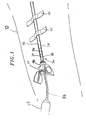
- FIG. 1 illustrates a catheter grip 20 in accordance with an embodiment of the present invention.
- the grip 20 is adapted to releasably grip and hold a catheter 22 in use in a patient's body for treatment or evaluation, such as mapping, ablation and the like. Once it is clamped on the catheter, the grip 20 effectively minimizes, if not prevents, the catheter from moving or shifting within the patient's body. As such, the grip 20 frees the hands of the attending doctor once he has closed the grip on the catheter.
- the catheter 22, as with most conventional catheters has the elongated catheter body 24 that extends between a catheter tip section 26 and a control handle 28.
- the catheter body 22 and the catheter tip 26 are portions that generally enter the patient's body, whereas the control handle 28 remains outside the body.
- the catheter grip 20 is adapted for use with an introducer or sheath 30 having a tubular needle 32 that is inserted into a patient's vein or artery, typically in a leg 33.
- Introducers, sheaths are generally known and can take on many different configurations. Most have a valve 34 that is provided at the proximal end of the needle. The valve may or may not have a side port 36 for the introduction of a fluid to the entry site of the tubular needle 32 .
- the introducer or sheath (used interchangeably herein) is generally used to facilitate the entry of the catheter tip 26 (not shown) and body 24 into the vein by providing a prepared portal into the patient's body through the valve 34 and the needle 32 .
- the grip 20 is configured as a cylinder or barrel which functions in part as a coupling hub 38 that attaches to the proximal end of the valve 34 before or, more preferably, after the introducer 30 has already been inserted and secured to the patient by conventional methods, such as medical tape and bandages 39 .
- the valve 34 and the hub 38 are releasably coupled to the extent that inadvertent detachment is avoided but intentional decoupling is facilitated.
- the valve and the hub can be snap-fitted, threaded, latched together and/or detachably coupled by other similar methods.
- valve and hub are frictionally engaged by means of a female fitting formed in the proximal end of the valve and a closely-conforming male fitting formed in the distal end of the hub.
- the grip 20 is preferably constructed of a suitably rigid material (including plastic, steel, synthetic or natural rubber, and the like, or combinations thereof) to accomplish its function of holding and maintaining the catheter in position in the patient's body.
- the catheter tip 26 and body 24 can be inserted through the grip and the coupled introducer for entry into the patient's body further through the needle 32 .
- the hub 38 is also configured with a channel 40 that extends between a distal end 42 and a proximal end 44 , the latter of which has an aperture 46 formed in an end wall 48 that extends across the channel.
- the aperture 46 and the hub 38 are generally concentric about an axis 50 through the channel 40 and each is configured to permit the passing and generally free movement of the catheter tip section 26 and body 24 distally and proximally through the channel 40 .
- the grip 20 includes a pair of grip members 52 situated on a proximal surface 54 of the wall 48 .
- the grip members 52 are aligned along a diameter 56 of the proximal surface 54 and face each other from across the aperture 46 .
- the grip members 52 can move radially inward toward each other to clamp onto the catheter body 24 extending through the aperture 46 and the channel 40 .
- the grip members 52 travel on a first track 58 formed in the proximal surface 54 along the diameter 56 , which is illustrated with a generally vertical orientation.
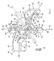
- the grip members 52 and the track 58 are engaged with each other by means of corresponding male and female fitting portions. Referring also to FIG.
- the disclosed embodiment of the track 58 has a slot 60 with a T-shaped cross-section 62 which receives a ridge 64 with a T-shaped cross-section 66 formed in a distal surface 68 of each grip member 52.
- the grip members 52 Guided by the track 58, the grip members 52 are slidable inwardly and outwardly along the diameter 56.
- the aperture 46 itself need not be (and is not) physically affected by movement of the grip members 52. It is therefore also understood that the aperture may be configured at any location along the length of the channel 40 and that the grip members 52 need not be in close proximity to nor proximal of the aperture 46. However, because the aperture 46 can guide the travel path of the catheter body 24 in the channel, it may be preferable in most instances that the grip members 52 and the aperture 46 be configured at least adjacent to each other along the channel 40. In the illustrated embodiment, the grip members and the aperture are in close proximity of each other and the grip members are immediately proximal of the aperture.
- an inner end 70 of each grip member 52 is configured with a notch 72 so that the pair can have a more secure hold on the catheter body 24 between them.
- the notch 72 provides better conformity between the interfacing inner ends 70 and the circumference of the catheter body 24.
- the inner ends may or may not be in contact with each other when the grip members 52 are clamped on the catheter body 24.
- the grip members 52 having a greater frictional contact with the catheter body as provided by the notches, minimize if not prevent translational or rotational movement in the catheter body once released from the hands of the doctor.
- surface 74 of the notches 72 may be textured and/or covered with a friction-inducing material 76 (not shown).
- the grip members 52 "rest” in a closed (or grip) position, as shown in FIGS. 3 and 6 , under the bias of an elastic member or band 78 shown in FIG. 2 .
- the elastic member sits in a groove 80 configured in an outer section 82 of each grip member 52.
- the elastic member 78 exerts around its circumference a force directed radially inward such that the grip members 52 are under a predetermined bias to move toward (if not to make contact with) each other and/or remain in the closed position until actively opened by the user.
- the grip has a pair of separator or wedgers 84 that are also situated on the proximal face 54 but along a diameter 86 that is offset between about 60-120 degrees, and more preferably about 90 degrees, from the diameter 56 of the grip members 52.
- the wedgers 84 face each other from across the aperture 46 and can move toward and away from each other.
- the catheter body 24 is released by the grip 20 when the grip members 52 are separated or driven away from each other, that is, radially outward, by the wedgers 84, as shown in FIG. 7 .
- the wedgers 84 travel along a track 88 also formed in the proximal surface 54 along the diameter 86, best seen in FIG. 5 , with a generally horizontal orientation.
- the wedgers 84 and the track 88 are engaged with each other by similar means of a male and female fitting portion.
- the track 88 has a slot 90 with a T-shaped cross-section 92 which receives a ridge 94 with a T-shaped cross-section 96 formed in a distal surface of each wedger 84.
- the wedgers 84 can slide inwardly and outwardly along the diameter 86 of the surface 54.
- the wedgers 84 and the grip members 52 interact and are interdependent, as described below in further detail, they have portions that affect and/or contact each other and are therefore in close proximity of each other within the grip.
- the wedgers 84 serve to wedge between and drive apart the grip members 52 in releasing the latter's hold on the catheter body 24.
- Inner ends 98 and 100 of the grip members 52 and the wedgers 84, respectively, are angled or chamfered at their corners 99 and 101, for example, at an angle ranging between about 30 and 60 degrees, and preferably at about 45 degrees, to facilitate this action.
- the convergence at the inner ends 100 of the wedgers 84 however is not to a point so the inner ends 100 will not protrude toward the catheter body 24 to the extent they contact or cause interfere with the catheter body 24.
- the inner ends 98 and 100 can be angled at a complementary angle, for example, where the total of the angles of the inner ends equals about 90 degrees).
- the slant or degree of angle of the inner ends may be varied for different efficiencies of operation. For example, a more obtuse angle may offer a different feel or tension in the operation of the grip 20, than would a more acute angle.
- the angle (which may or may not be identical between the wedge members 84 and the grip members 52) may also depend on or relate to the offset angle between the tracks 56 and 86.
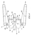
- the grip members 52 are moved toward each other for a closed or grip position ( FIG. 6 ), and away from each other for a release position ( FIG. 7 ).
- the wedge members 84 are moved toward each other for a wedge position ( FIG. 7 ), and away from each other for a separated position ( FIG. 6 ).
- Movement of the wedge members 84 toward each other to release the catheter body 24 is actuated primarily by means of a pair of tabs 102 that the user actuates.
- the tabs are pivotably attached to hinges 104 provided on the hub 38 and situated generally on the diameter 86 in alignment with the wedgers 84.
- the hub may be indexed to facilitate this alignment.
- the hinges 104 are distal of the surface 54 and the tabs 102 extend slightly proximally from the hub 38 with their free ends 106 separated by a maximum distance which decreases to a minimum distance when the tabs are squeezed together by the user.
- the tabs act on the wedgers 84 through an angled ridge or cam 108 provided on an inner surface 110 of each tab. As can be seen in FIG. 7 , as the free ends 106 approach each other, each cam 108 engages an adjacent wedger 84 to drive it inwardly toward its mate.
- the tabs 102 are biased away from each other by leaf springs 112 (best seen in FIGS. 6 and 7 ) such that the tabs spring apart when the user stops squeezing.
- the bias of the elastic member 78 around the grip members 52 also tends to urge the wedgers 84 to move away from each other.
- the wedge members 80 therefore "rest” apart from each other (at their maximum separation) until they are moved toward each other by the tabs.
- the tabs may be biased to spring apart by other means.
- the leaf springs 112 may be connected or be integrated a single piece extending across the channel 40 to leverage the tabs 102 against each other so they move in a coordinated manner, that is, similarly and coincidentally.
- a doctor can use the very hand working the introducer 30 to actuate the tabs 102, and do so without changing hand position.
- the grip 20 therefore provides improved ergonomics for the doctor, if not a more versatile working environment in which he has more mobility, or at least more freedom with his hands once the grip 20 is closed on the catheter body 24.
- the grip 20 rests in the closed position, with the grip members 52 being in contact with each other under the bias of the elastic member 78 and the wedgers 84 separated and generally free from compression by the tabs 102 ( FIG. 3 ).
- the doctor opens the grip 20 so that he can pass the catheter tip and body through the aperture 46 and into the introducer 30.
- the cams 108 press on the wedgers 84 inwardly keeping the grip members 52 wedged apart.
- the catheter body 24 can then be advanced by rotation or translation to the grip 20 as needed to reach the target site inside the patient's body ( FIG. 7 ).
- the doctor releases the tabs 102 which separate under the force of the leaf spring 112. Without any compressive force pushing the wedgers 84, they are forced outwardly by the inwardly-moving grip members 52 acting under the force of the elastic member 78 which clamps the grip members 52 on the catheter body 24 ( FIG. 6 ).
- the notches 72 close around the circumference of the catheter body and the friction-inducing surface 74 securely holds the catheter body 24 to resist sliding or twisting caused by any torsional or coiled energy stored in the catheter body.
- the doctor re-squeezes the tabs 102 to re-separate the grip members 52. Indeed, release of the grip 20 to separate the grip members 52 at any time can be momentary or of a longer duration as desired by the doctor.
- the grip can be biased toward the open position, such that a band acts to close the wedge members with a leaf spring and/or the tabs separating the grip members.
- the tabs may be take on a different shape or extend from the hinge at a different angle.
Landscapes
- Health & Medical Sciences (AREA)
- Life Sciences & Earth Sciences (AREA)
- Biophysics (AREA)
- Pulmonology (AREA)
- Engineering & Computer Science (AREA)
- Anesthesiology (AREA)
- Biomedical Technology (AREA)
- Heart & Thoracic Surgery (AREA)
- Hematology (AREA)
- Animal Behavior & Ethology (AREA)
- General Health & Medical Sciences (AREA)
- Public Health (AREA)
- Veterinary Medicine (AREA)
- Media Introduction/Drainage Providing Device (AREA)
Claims (19)
- Pince (20) destinée à être utilisée avec un cathéter ayant un corps de cathéter allongé (24), comprenant :→ un raccord (38) avec un canal à travers lequel le corps de cathéter peut s'étendre, le raccord ayant une surface s'étendant sur le canal ;→ un premier rail (58) configuré le long d'un premier diamètre de la surface, un second rail (88) configuré le long d'un second diamètre de la surface, lesdits premier et second diamètres étant angulairement décalés l'un de l'autre ;→ une paire d'éléments de pince (52) adaptés pour se déplacer l'un vers l'autre le long dudit premier rail (58) et maintenir entre eux le corps de cathéter (24) ;→ une paire de séparateurs (84) adaptés pour se déplacer l'un vers l'autre le long dudit second rail (88) et séparer les éléments de pince afin de libérer le corps de cathéter (24) ; et→ une paire d'actionneurs configurés pour entraîner les séparateurs vers les éléments de pince en réponse à la manipulation par un utilisateur.
- Pince pour cathéter selon la revendication 1, dans laquelle les actionneurs sont sollicités contre l'entraînement des séparateurs vers les éléments de pince.
- Pince pour cathéter selon la revendication 1, dans laquelle les éléments de pince se déplacent l'un vers l'autre lorsque les séparateurs s'éloignent l'un de l'autre.
- Pince pour cathéter selon la revendication 1, dans laquelle les séparateurs se déplacent l'un vers l'autre lorsque les éléments de pince s'éloignent l'un de l'autre.
- Pince pour cathéter selon la revendication 1, comprenant en outre un élément de sollicitation sollicitant les éléments de pince l'un vers l'autre.
- Pince pour cathéter selon la revendication 1, dans laquelle lesdits rails sont angulairement décalés selon un angle prédéterminé d'environ 90 degrés.
- Pince pour cathéter selon la revendication 1, dans laquelle ladite surface est formée sur une paroi s'étendant sur le canal, la paroi ayant une ouverture à travers laquelle le corps de cathéter s'étend.
- Pince pour cathéter selon la revendication 1, dans laquelle le raccord est adapté pour être couplé avec un dispositif d'introduction ou une gaine.
- Pince pour cathéter selon la revendication 1, dans laquelle l'un parmi le premier rail et les éléments de pince a une partie de mise en prise mâle et l'autre parmi le premier rail et les éléments de pince a une partie de mise en prise femelle, dans laquelle la partie de mise en prise mâle est reçue dans la partie de mise en prise femelle.
- Pince pour cathéter selon la revendication 1, dans laquelle l'un parmi le second rail et les séparateurs a une partie de mise en prise mâle et l'autre parmi le second rail et les séparateurs a une partie de mise en prise femelle correspondante, dans laquelle la partie de mise en prise mâle est reçue dans la partie de mise en prise femelle.
- Pince pour cathéter selon la revendication 1, dans laquelle les extrémités internes des séparateurs et des éléments de pince sont coudées.
- Pince pour cathéter selon la revendication 1, dans laquelle les extrémités internes des éléments de pince ont une encoche.
- Pince pour cathéter selon la revendication 1, dans laquelle le raccord est adapté pour se coupler avec un dispositif d'introduction ou une gaine, chaque actionneur a une surface de came agissant sur une extrémité externe d'un séparateur différent et les éléments de pince sont sollicités l'un vers l'autre et les actionneurs sont sollicités contre l'entraînement des séparateurs vers les éléments de pince.
- Pince pour cathéter selon la revendication 13, dans laquelle la pince est couplée à une extrémité proximale du dispositif d'introduction ou de la gaine.
- Pince pour cathéter selon la revendication 13, dans laquelle les actionneurs sont adaptés pour être comprimés l'un vers l'autre par l'utilisateur.
- Pince pour cathéter selon la revendication 13, dans laquelle la surface est configurée sur une paroi s'étendant sur le canal, la paroi ayant une ouverture à travers laquelle le corps de cathéter s'étend.
- Pince pour cathéter selon la revendication 16, dans laquelle la paroi est à une extrémité proximale du raccord et les éléments de pince et les séparateurs sont à proximité de l'ouverture.
- Pince pour cathéter selon la revendication 15, dans laquelle les actionneurs sont articulés par rapport au raccord généralement le long du second diamètre.
- Pince pour cathéter selon la revendication 18, dans laquelle les actionneurs sont configurés pour être manipulés par une main de l'utilisateur.
Applications Claiming Priority (2)
| Application Number | Priority Date | Filing Date | Title |
|---|---|---|---|
| US10/871,677 US7104982B2 (en) | 2004-06-14 | 2004-06-14 | Catheter grip |
| PCT/US2005/020927 WO2005123167A1 (fr) | 2004-06-14 | 2005-06-14 | Pince pour catheter |
Publications (2)
| Publication Number | Publication Date |
|---|---|
| EP1763377A1 EP1763377A1 (fr) | 2007-03-21 |
| EP1763377B1 true EP1763377B1 (fr) | 2009-12-02 |
Family
ID=34979896
Family Applications (1)
| Application Number | Title | Priority Date | Filing Date |
|---|---|---|---|
| EP05761165A Ceased EP1763377B1 (fr) | 2004-06-14 | 2005-06-14 | Pince pour catheter |
Country Status (9)
| Country | Link |
|---|---|
| US (2) | US7104982B2 (fr) |
| EP (1) | EP1763377B1 (fr) |
| JP (1) | JP4732452B2 (fr) |
| AT (1) | ATE450287T1 (fr) |
| AU (1) | AU2005254558B2 (fr) |
| CA (1) | CA2570397C (fr) |
| DE (1) | DE602005018055D1 (fr) |
| MX (1) | MXPA06014652A (fr) |
| WO (1) | WO2005123167A1 (fr) |
Families Citing this family (18)
| Publication number | Priority date | Publication date | Assignee | Title |
|---|---|---|---|---|
| US7104982B2 (en) * | 2004-06-14 | 2006-09-12 | Biosense Webster Inc | Catheter grip |
| US7947019B2 (en) * | 2006-08-18 | 2011-05-24 | Angio Dynamics, Inc | Catheter retention assembly and method of use |
| US7699809B2 (en) | 2006-12-14 | 2010-04-20 | Urmey William F | Catheter positioning system |
| WO2009157873A1 (fr) * | 2008-06-27 | 2009-12-30 | Singapore Health Services Pte. Ltd. | Valve hémostatique |
| US7955782B2 (en) * | 2008-09-22 | 2011-06-07 | Honeywell International Inc. | Bottom antireflective coatings exhibiting enhanced wet strip rates, bottom antireflective coating compositions for forming bottom antireflective coatings, and methods for fabricating the same |
| BRMU8802275U2 (pt) * | 2008-10-13 | 2010-10-05 | Scitech Produtos Medicos Ltda | dispositivo de trava tangencial de acionamento rotacional e axial sobre fuso para sistema de liberação de endoprótese tubular |
| US8414604B2 (en) * | 2008-10-13 | 2013-04-09 | Covidien Lp | Devices and methods for manipulating a catheter shaft |
| AU2015200135B2 (en) * | 2009-10-15 | 2017-03-02 | Biosense Webster, Inc. | Catheter sheath introducer with rotational lock |
| US8808248B2 (en) * | 2009-10-15 | 2014-08-19 | Biosense Webster, Inc. | Catheter sheath introducer with rotational lock |
| EP3263038B1 (fr) | 2011-05-18 | 2023-08-30 | Solo-Dex, Inc. | Appareil de conduction nerveuse d'anesthésie continue |
| US8986283B2 (en) | 2011-05-18 | 2015-03-24 | Solo-Dex, Llc | Continuous anesthesia nerve conduction apparatus, system and method thereof |
| US9320872B2 (en) | 2011-10-14 | 2016-04-26 | William F. Urmey | Catheter positioning system |
| AU2013337807B2 (en) * | 2012-11-01 | 2016-12-08 | Muffin Incorporated | Implements for identifying sheath migration |
| KR101248472B1 (ko) * | 2013-01-04 | 2013-04-03 | (주)휴바이오메드 | 지혈 밸브장치 |
| US10596349B2 (en) * | 2014-02-05 | 2020-03-24 | Biosense Webster (Israel) Ltd. | Catheter clips |
| USD820976S1 (en) * | 2017-02-20 | 2018-06-19 | Cletus Petersen | Respiratory cheek pad |
| SG11202012641UA (en) * | 2018-06-20 | 2021-01-28 | Saban Ventures Pty Ltd | Clamp for a medical device |
| JP7265262B2 (ja) * | 2019-12-06 | 2023-04-26 | 株式会社東海メディカルプロダクツ | Y型コネクタ及びアーム。 |
Family Cites Families (21)
| Publication number | Priority date | Publication date | Assignee | Title |
|---|---|---|---|---|
| US2234686A (en) * | 1940-01-02 | 1941-03-11 | Ind Patents Corp | Needle and clamp therefor |
| US3487837A (en) * | 1967-02-06 | 1970-01-06 | Roy A Petersen | Device for holding catheters in position |
| US3821957A (en) * | 1973-05-02 | 1974-07-02 | East West Med Prod | Retention slide for catheters and other tubular materials |
| US4362156A (en) * | 1979-04-18 | 1982-12-07 | Riverain Corporation | Intravenous infusion assembly |
| GB2214816A (en) * | 1988-02-15 | 1989-09-13 | Michael Frank Smith | Catheter grip |
| US5078703A (en) | 1989-10-13 | 1992-01-07 | Abbott Laboratories | Catheter adapter and retainer |
| US5127626A (en) * | 1989-10-31 | 1992-07-07 | Applied Vascular Devices, Inc. | Apparatus for sealing around members extending therethrough |
| US5098392A (en) * | 1991-06-28 | 1992-03-24 | Fleischhacker John J | Locking dilator for peel away introducer sheath |
| EP0699086B1 (fr) * | 1993-05-18 | 1997-07-02 | Btg International Limited | Dispositif permettant d'effectuer le catheterisme urinaire passager chez une femme |
| US5437645A (en) * | 1993-10-08 | 1995-08-01 | United States Surgical Corporation | Surgical instrument positioning device |
| US5651771A (en) * | 1994-11-07 | 1997-07-29 | Applied Medical Resources Corporation | Adjustable surgical clamp |
| US5836914A (en) * | 1995-09-15 | 1998-11-17 | Becton Dickinson And Company | Method and apparatus for variably regulating the length of a combined spinal-epidural needle |
| US5792112A (en) * | 1995-10-20 | 1998-08-11 | Applied Medical Resources Corporation | Trocar with electrical discharge path |
| US6083207A (en) * | 1998-12-08 | 2000-07-04 | Daig Corporation | Partitioned hemostasis valve system |
| US5921968A (en) * | 1997-11-25 | 1999-07-13 | Merit Medical Systems, Inc. | Valve apparatus with adjustable quick-release mechanism |
| US5931671A (en) * | 1998-01-28 | 1999-08-03 | Hoffman; Elliott S. | Dental saliva ejector tube assembly |
| DE19826746C1 (de) | 1998-06-16 | 1999-11-25 | Sulzer Osypka Gmbh | Katheter mit zusätzlichem Handgriff |
| US6589262B1 (en) * | 2000-03-31 | 2003-07-08 | Medamicus, Inc. | Locking catheter introducing system |
| US6558354B1 (en) * | 2000-08-04 | 2003-05-06 | Becton Dickinson And Company | Adapter for connecting an introducer needle assembly to a catheter introducer |
| US6966896B2 (en) * | 2002-09-04 | 2005-11-22 | Paul A. Kurth | Introducer and hemostatic valve combination and method of using the same |
| US7104982B2 (en) * | 2004-06-14 | 2006-09-12 | Biosense Webster Inc | Catheter grip |
-
2004
- 2004-06-14 US US10/871,677 patent/US7104982B2/en not_active Expired - Lifetime
-
2005
- 2005-06-14 AU AU2005254558A patent/AU2005254558B2/en not_active Ceased
- 2005-06-14 JP JP2007516634A patent/JP4732452B2/ja not_active Expired - Fee Related
- 2005-06-14 AT AT05761165T patent/ATE450287T1/de not_active IP Right Cessation
- 2005-06-14 MX MXPA06014652A patent/MXPA06014652A/es unknown
- 2005-06-14 WO PCT/US2005/020927 patent/WO2005123167A1/fr not_active Ceased
- 2005-06-14 DE DE602005018055T patent/DE602005018055D1/de not_active Expired - Lifetime
- 2005-06-14 EP EP05761165A patent/EP1763377B1/fr not_active Ceased
- 2005-06-14 CA CA2570397A patent/CA2570397C/fr not_active Expired - Fee Related
-
2006
- 2006-08-03 US US11/499,178 patent/US7628783B2/en not_active Expired - Fee Related
Also Published As
| Publication number | Publication date |
|---|---|
| US7628783B2 (en) | 2009-12-08 |
| JP4732452B2 (ja) | 2011-07-27 |
| JP2008502429A (ja) | 2008-01-31 |
| CA2570397A1 (fr) | 2005-12-29 |
| ATE450287T1 (de) | 2009-12-15 |
| DE602005018055D1 (de) | 2010-01-14 |
| WO2005123167A1 (fr) | 2005-12-29 |
| US7104982B2 (en) | 2006-09-12 |
| US20060267063A1 (en) | 2006-11-30 |
| AU2005254558B2 (en) | 2010-08-19 |
| AU2005254558A1 (en) | 2005-12-29 |
| US20050277909A1 (en) | 2005-12-15 |
| CA2570397C (fr) | 2013-05-28 |
| MXPA06014652A (es) | 2008-03-13 |
| EP1763377A1 (fr) | 2007-03-21 |
Similar Documents
| Publication | Publication Date | Title |
|---|---|---|
| EP1763377B1 (fr) | Pince pour catheter | |
| US5865800A (en) | Deflectable catheter | |
| US12178461B2 (en) | Actuation mechanism with grooved actuation levers | |
| US7686826B2 (en) | Surgical instrument | |
| US8083765B2 (en) | Surgical instrument | |
| US6976955B2 (en) | Handle for medical devices, and medical device assemblies including a handle | |
| EP3209217B1 (fr) | Dispositif de couple | |
| JPH0230694B2 (fr) | ||
| US8444626B2 (en) | Articulating handle for a deflectable catheter and method therefor | |
| JP6996013B1 (ja) | トラッピングバルーンカテーテル | |
| WO2025145000A1 (fr) | Pince hémostatique commandée par un médecin dotée d'une poignée actionnée par une seule main | |
| HK1133567B (en) | Surgical instrument |
Legal Events
| Date | Code | Title | Description |
|---|---|---|---|
| PUAI | Public reference made under article 153(3) epc to a published international application that has entered the european phase |
Free format text: ORIGINAL CODE: 0009012 |
|
| 17P | Request for examination filed |
Effective date: 20070112 |
|
| AK | Designated contracting states |
Kind code of ref document: A1 Designated state(s): AT BE BG CH CY CZ DE DK EE ES FI FR GB GR HU IE IS IT LI LT LU MC NL PL PT RO SE SI SK TR |
|
| RIN1 | Information on inventor provided before grant (corrected) |
Inventor name: MCDANIEL, BENJAMIN, D. |
|
| DAX | Request for extension of the european patent (deleted) | ||
| 17Q | First examination report despatched |
Effective date: 20090513 |
|
| GRAP | Despatch of communication of intention to grant a patent |
Free format text: ORIGINAL CODE: EPIDOSNIGR1 |
|
| GRAS | Grant fee paid |
Free format text: ORIGINAL CODE: EPIDOSNIGR3 |
|
| GRAA | (expected) grant |
Free format text: ORIGINAL CODE: 0009210 |
|
| AK | Designated contracting states |
Kind code of ref document: B1 Designated state(s): AT BE BG CH CY CZ DE DK EE ES FI FR GB GR HU IE IS IT LI LT LU MC NL PL PT RO SE SI SK TR |
|
| REG | Reference to a national code |
Ref country code: GB Ref legal event code: FG4D |
|
| REG | Reference to a national code |
Ref country code: CH Ref legal event code: EP |
|
| REG | Reference to a national code |
Ref country code: IE Ref legal event code: FG4D |
|
| REF | Corresponds to: |
Ref document number: 602005018055 Country of ref document: DE Date of ref document: 20100114 Kind code of ref document: P |
|
| REG | Reference to a national code |
Ref country code: NL Ref legal event code: T3 |
|
| PG25 | Lapsed in a contracting state [announced via postgrant information from national office to epo] |
Ref country code: SE Free format text: LAPSE BECAUSE OF FAILURE TO SUBMIT A TRANSLATION OF THE DESCRIPTION OR TO PAY THE FEE WITHIN THE PRESCRIBED TIME-LIMIT Effective date: 20091202 Ref country code: FI Free format text: LAPSE BECAUSE OF FAILURE TO SUBMIT A TRANSLATION OF THE DESCRIPTION OR TO PAY THE FEE WITHIN THE PRESCRIBED TIME-LIMIT Effective date: 20091202 Ref country code: LT Free format text: LAPSE BECAUSE OF FAILURE TO SUBMIT A TRANSLATION OF THE DESCRIPTION OR TO PAY THE FEE WITHIN THE PRESCRIBED TIME-LIMIT Effective date: 20091202 |
|
| LTIE | Lt: invalidation of european patent or patent extension |
Effective date: 20091202 |
|
| PG25 | Lapsed in a contracting state [announced via postgrant information from national office to epo] |
Ref country code: SI Free format text: LAPSE BECAUSE OF FAILURE TO SUBMIT A TRANSLATION OF THE DESCRIPTION OR TO PAY THE FEE WITHIN THE PRESCRIBED TIME-LIMIT Effective date: 20091202 Ref country code: CY Free format text: LAPSE BECAUSE OF FAILURE TO SUBMIT A TRANSLATION OF THE DESCRIPTION OR TO PAY THE FEE WITHIN THE PRESCRIBED TIME-LIMIT Effective date: 20091202 Ref country code: PL Free format text: LAPSE BECAUSE OF FAILURE TO SUBMIT A TRANSLATION OF THE DESCRIPTION OR TO PAY THE FEE WITHIN THE PRESCRIBED TIME-LIMIT Effective date: 20091202 |
|
| PG25 | Lapsed in a contracting state [announced via postgrant information from national office to epo] |
Ref country code: AT Free format text: LAPSE BECAUSE OF FAILURE TO SUBMIT A TRANSLATION OF THE DESCRIPTION OR TO PAY THE FEE WITHIN THE PRESCRIBED TIME-LIMIT Effective date: 20091202 |
|
| PG25 | Lapsed in a contracting state [announced via postgrant information from national office to epo] |
Ref country code: RO Free format text: LAPSE BECAUSE OF FAILURE TO SUBMIT A TRANSLATION OF THE DESCRIPTION OR TO PAY THE FEE WITHIN THE PRESCRIBED TIME-LIMIT Effective date: 20091202 Ref country code: PT Free format text: LAPSE BECAUSE OF FAILURE TO SUBMIT A TRANSLATION OF THE DESCRIPTION OR TO PAY THE FEE WITHIN THE PRESCRIBED TIME-LIMIT Effective date: 20100402 Ref country code: EE Free format text: LAPSE BECAUSE OF FAILURE TO SUBMIT A TRANSLATION OF THE DESCRIPTION OR TO PAY THE FEE WITHIN THE PRESCRIBED TIME-LIMIT Effective date: 20091202 Ref country code: ES Free format text: LAPSE BECAUSE OF FAILURE TO SUBMIT A TRANSLATION OF THE DESCRIPTION OR TO PAY THE FEE WITHIN THE PRESCRIBED TIME-LIMIT Effective date: 20100313 Ref country code: IS Free format text: LAPSE BECAUSE OF FAILURE TO SUBMIT A TRANSLATION OF THE DESCRIPTION OR TO PAY THE FEE WITHIN THE PRESCRIBED TIME-LIMIT Effective date: 20100402 Ref country code: BG Free format text: LAPSE BECAUSE OF FAILURE TO SUBMIT A TRANSLATION OF THE DESCRIPTION OR TO PAY THE FEE WITHIN THE PRESCRIBED TIME-LIMIT Effective date: 20100302 |
|
| PG25 | Lapsed in a contracting state [announced via postgrant information from national office to epo] |
Ref country code: CZ Free format text: LAPSE BECAUSE OF FAILURE TO SUBMIT A TRANSLATION OF THE DESCRIPTION OR TO PAY THE FEE WITHIN THE PRESCRIBED TIME-LIMIT Effective date: 20091202 Ref country code: BE Free format text: LAPSE BECAUSE OF FAILURE TO SUBMIT A TRANSLATION OF THE DESCRIPTION OR TO PAY THE FEE WITHIN THE PRESCRIBED TIME-LIMIT Effective date: 20091202 Ref country code: SK Free format text: LAPSE BECAUSE OF FAILURE TO SUBMIT A TRANSLATION OF THE DESCRIPTION OR TO PAY THE FEE WITHIN THE PRESCRIBED TIME-LIMIT Effective date: 20091202 |
|
| PLBE | No opposition filed within time limit |
Free format text: ORIGINAL CODE: 0009261 |
|
| STAA | Information on the status of an ep patent application or granted ep patent |
Free format text: STATUS: NO OPPOSITION FILED WITHIN TIME LIMIT |
|
| PG25 | Lapsed in a contracting state [announced via postgrant information from national office to epo] |
Ref country code: GR Free format text: LAPSE BECAUSE OF FAILURE TO SUBMIT A TRANSLATION OF THE DESCRIPTION OR TO PAY THE FEE WITHIN THE PRESCRIBED TIME-LIMIT Effective date: 20100303 |
|
| 26N | No opposition filed |
Effective date: 20100903 |
|
| PG25 | Lapsed in a contracting state [announced via postgrant information from national office to epo] |
Ref country code: MC Free format text: LAPSE BECAUSE OF NON-PAYMENT OF DUE FEES Effective date: 20100630 Ref country code: DK Free format text: LAPSE BECAUSE OF FAILURE TO SUBMIT A TRANSLATION OF THE DESCRIPTION OR TO PAY THE FEE WITHIN THE PRESCRIBED TIME-LIMIT Effective date: 20091202 |
|
| REG | Reference to a national code |
Ref country code: CH Ref legal event code: PL |
|
| PG25 | Lapsed in a contracting state [announced via postgrant information from national office to epo] |
Ref country code: LI Free format text: LAPSE BECAUSE OF NON-PAYMENT OF DUE FEES Effective date: 20100630 Ref country code: CH Free format text: LAPSE BECAUSE OF NON-PAYMENT OF DUE FEES Effective date: 20100630 |
|
| PG25 | Lapsed in a contracting state [announced via postgrant information from national office to epo] |
Ref country code: HU Free format text: LAPSE BECAUSE OF FAILURE TO SUBMIT A TRANSLATION OF THE DESCRIPTION OR TO PAY THE FEE WITHIN THE PRESCRIBED TIME-LIMIT Effective date: 20100603 Ref country code: LU Free format text: LAPSE BECAUSE OF NON-PAYMENT OF DUE FEES Effective date: 20100614 |
|
| PG25 | Lapsed in a contracting state [announced via postgrant information from national office to epo] |
Ref country code: TR Free format text: LAPSE BECAUSE OF FAILURE TO SUBMIT A TRANSLATION OF THE DESCRIPTION OR TO PAY THE FEE WITHIN THE PRESCRIBED TIME-LIMIT Effective date: 20091202 |
|
| REG | Reference to a national code |
Ref country code: FR Ref legal event code: PLFP Year of fee payment: 12 |
|
| REG | Reference to a national code |
Ref country code: FR Ref legal event code: PLFP Year of fee payment: 13 |
|
| REG | Reference to a national code |
Ref country code: FR Ref legal event code: PLFP Year of fee payment: 14 |
|
| PGFP | Annual fee paid to national office [announced via postgrant information from national office to epo] |
Ref country code: IT Payment date: 20190620 Year of fee payment: 15 Ref country code: DE Payment date: 20190604 Year of fee payment: 15 Ref country code: NL Payment date: 20190612 Year of fee payment: 15 Ref country code: IE Payment date: 20190610 Year of fee payment: 15 |
|
| PGFP | Annual fee paid to national office [announced via postgrant information from national office to epo] |
Ref country code: FR Payment date: 20190510 Year of fee payment: 15 |
|
| PGFP | Annual fee paid to national office [announced via postgrant information from national office to epo] |
Ref country code: GB Payment date: 20190612 Year of fee payment: 15 |
|
| REG | Reference to a national code |
Ref country code: DE Ref legal event code: R119 Ref document number: 602005018055 Country of ref document: DE |
|
| REG | Reference to a national code |
Ref country code: NL Ref legal event code: MM Effective date: 20200701 |
|
| GBPC | Gb: european patent ceased through non-payment of renewal fee |
Effective date: 20200614 |
|
| PG25 | Lapsed in a contracting state [announced via postgrant information from national office to epo] |
Ref country code: FR Free format text: LAPSE BECAUSE OF NON-PAYMENT OF DUE FEES Effective date: 20200630 Ref country code: GB Free format text: LAPSE BECAUSE OF NON-PAYMENT OF DUE FEES Effective date: 20200614 Ref country code: NL Free format text: LAPSE BECAUSE OF NON-PAYMENT OF DUE FEES Effective date: 20200701 Ref country code: IE Free format text: LAPSE BECAUSE OF NON-PAYMENT OF DUE FEES Effective date: 20200614 |
|
| PG25 | Lapsed in a contracting state [announced via postgrant information from national office to epo] |
Ref country code: DE Free format text: LAPSE BECAUSE OF NON-PAYMENT OF DUE FEES Effective date: 20210101 |
|
| PG25 | Lapsed in a contracting state [announced via postgrant information from national office to epo] |
Ref country code: IT Free format text: LAPSE BECAUSE OF NON-PAYMENT OF DUE FEES Effective date: 20200614 |