EP1763627B1 - Moteur thermique dote d'une epuration des gaz d'echappement et procede pour le faire fonctionner - Google Patents
Moteur thermique dote d'une epuration des gaz d'echappement et procede pour le faire fonctionner Download PDFInfo
- Publication number
- EP1763627B1 EP1763627B1 EP05770233A EP05770233A EP1763627B1 EP 1763627 B1 EP1763627 B1 EP 1763627B1 EP 05770233 A EP05770233 A EP 05770233A EP 05770233 A EP05770233 A EP 05770233A EP 1763627 B1 EP1763627 B1 EP 1763627B1
- Authority
- EP
- European Patent Office
- Prior art keywords
- exhaust gas
- combustion chamber
- group
- exhaust
- line
- Prior art date
- Legal status (The legal status is an assumption and is not a legal conclusion. Google has not performed a legal analysis and makes no representation as to the accuracy of the status listed.)
- Expired - Lifetime
Links
Images

Classifications
-
- F—MECHANICAL ENGINEERING; LIGHTING; HEATING; WEAPONS; BLASTING
- F02—COMBUSTION ENGINES; HOT-GAS OR COMBUSTION-PRODUCT ENGINE PLANTS
- F02B—INTERNAL-COMBUSTION PISTON ENGINES; COMBUSTION ENGINES IN GENERAL
- F02B37/00—Engines characterised by provision of pumps driven at least for part of the time by exhaust
- F02B37/02—Gas passages between engine outlet and pump drive, e.g. reservoirs
- F02B37/025—Multiple scrolls or multiple gas passages guiding the gas to the pump drive
-
- F—MECHANICAL ENGINEERING; LIGHTING; HEATING; WEAPONS; BLASTING
- F01—MACHINES OR ENGINES IN GENERAL; ENGINE PLANTS IN GENERAL; STEAM ENGINES
- F01N—GAS-FLOW SILENCERS OR EXHAUST APPARATUS FOR MACHINES OR ENGINES IN GENERAL; GAS-FLOW SILENCERS OR EXHAUST APPARATUS FOR INTERNAL-COMBUSTION ENGINES
- F01N3/00—Exhaust or silencing apparatus having means for purifying, rendering innocuous, or otherwise treating exhaust
- F01N3/08—Exhaust or silencing apparatus having means for purifying, rendering innocuous, or otherwise treating exhaust for rendering innocuous
- F01N3/10—Exhaust or silencing apparatus having means for purifying, rendering innocuous, or otherwise treating exhaust for rendering innocuous by thermal or catalytic conversion of noxious components of exhaust
- F01N3/18—Exhaust or silencing apparatus having means for purifying, rendering innocuous, or otherwise treating exhaust for rendering innocuous by thermal or catalytic conversion of noxious components of exhaust characterised by methods of operation; Control
- F01N3/20—Exhaust or silencing apparatus having means for purifying, rendering innocuous, or otherwise treating exhaust for rendering innocuous by thermal or catalytic conversion of noxious components of exhaust characterised by methods of operation; Control specially adapted for catalytic conversion
- F01N3/2053—By-passing catalytic reactors, e.g. to prevent overheating
-
- F—MECHANICAL ENGINEERING; LIGHTING; HEATING; WEAPONS; BLASTING
- F02—COMBUSTION ENGINES; HOT-GAS OR COMBUSTION-PRODUCT ENGINE PLANTS
- F02B—INTERNAL-COMBUSTION PISTON ENGINES; COMBUSTION ENGINES IN GENERAL
- F02B37/00—Engines characterised by provision of pumps driven at least for part of the time by exhaust
- F02B37/12—Control of the pumps
- F02B37/18—Control of the pumps by bypassing exhaust from the inlet to the outlet of turbine or to the atmosphere
-
- F—MECHANICAL ENGINEERING; LIGHTING; HEATING; WEAPONS; BLASTING
- F01—MACHINES OR ENGINES IN GENERAL; ENGINE PLANTS IN GENERAL; STEAM ENGINES
- F01N—GAS-FLOW SILENCERS OR EXHAUST APPARATUS FOR MACHINES OR ENGINES IN GENERAL; GAS-FLOW SILENCERS OR EXHAUST APPARATUS FOR INTERNAL-COMBUSTION ENGINES
- F01N2410/00—By-passing, at least partially, exhaust from inlet to outlet of apparatus, to atmosphere or to other device
-
- Y—GENERAL TAGGING OF NEW TECHNOLOGICAL DEVELOPMENTS; GENERAL TAGGING OF CROSS-SECTIONAL TECHNOLOGIES SPANNING OVER SEVERAL SECTIONS OF THE IPC; TECHNICAL SUBJECTS COVERED BY FORMER USPC CROSS-REFERENCE ART COLLECTIONS [XRACs] AND DIGESTS
- Y02—TECHNOLOGIES OR APPLICATIONS FOR MITIGATION OR ADAPTATION AGAINST CLIMATE CHANGE
- Y02T—CLIMATE CHANGE MITIGATION TECHNOLOGIES RELATED TO TRANSPORTATION
- Y02T10/00—Road transport of goods or passengers
- Y02T10/10—Internal combustion engine [ICE] based vehicles
- Y02T10/12—Improving ICE efficiencies
Definitions
- the invention relates to an internal combustion engine having at least a first and a second group of one or more combustion chambers, wherein the one or more combustion chambers of the first group are supplied with fuel independently of the one or more combustion chambers of the second group, and an exhaust line with a first, from the exhaust gas branch line leading off the first combustion chamber group and a second exhaust branch line discharging from the second combustion chamber group and having at least one exhaust gas aftertreatment unit which is in communication with the first and second exhaust branch lines on the inlet side, and a method for operating such an internal combustion engine.
- the DE 30 17 468 C2 describes an internal combustion engine with cylinder deactivation with a first and second cylinder group and with an intake system with two intake chambers, which are each connected to one of the two cylinder groups. Between the suction chambers a lockable connection is provided.
- An exhaust system has two exhaust chambers connected to each of the cylinder groups and merging at a point downstream of cylinder outlets. When the load is high, both cylinder groups are kept in operation, but only the first cylinder group when the load is low.
- the intake chambers are each connected via an exhaust gas recirculation line to one of the exhaust gas chambers.
- the exhaust gas recirculation lines are interconnected by a branch line with changeover valve.
- the switching valve closes the branch line in the case of a high load state and, in the case of a low load state, that part of the first exhaust gas return line located upstream of the branch line of the branch line.
- the DE 30 36 508 A1 describes a multi-cylinder piston internal combustion engine having a suction pipe connected to the cylinders and a first, connected to a first cylinder group exhaust manifold and a second, with a second Cylinder group has connected exhaust manifold. Downstream of a junction of the two exhaust manifolds is an exhaust aftertreatment unit.
- a first fuel supply device is provided for charging the first cylinder group with a fuel quantity corresponding to the power output.
- a second fuel supply device is provided for charging the second cylinder group with a fuel quantity corresponding to the power output and has a shut-off device for shutting off the second fuel supply device.
- a deflection device provided in the second exhaust manifold is designed for selective recirculation of exhaust gas from the second cylinder group with the second fuel supply device shut off into the intake manifold.
- the DE 195 00 761 C2 describes a multi-cylinder piston internal combustion engine having at least two cylinder groups, each having an inlet channel for supplying combustion air and an exhaust line with a catalyst, wherein a cylinder group in partial load operation of the internal combustion engine is switched off and at least a portion of the exhaust gas of the fired cylinder group via a front or behind the associated Catalyst branched return line is fed to the inlet duct of the deactivated cylinder group. It can be provided that the cylinder groups are alternately switched off and the exhaust gas lines of one or more fired cylinder groups are connected via a respective return line to the inlet channels of one or more deactivated cylinder groups. This is intended to achieve uniform heating or maintenance of the operating temperature of each catalytic converter.
- the DE 195 29 835 A1 describes an exhaust system of a gasoline engine with an exhaust pipe, one through a lambda probe regulated three-way oxidation catalyst and an SCR catalyst.
- the SCR catalytic converter is arranged in a bypass pipe running parallel to the exhaust gas pipeline between the lambda probe and the oxidation catalytic converter.
- the bypass pipe and / or the exhaust pipe are provided with an exhaust valve, which is controlled in each case depending on the temperatures of the SCR catalyst and the oxidation catalyst and the oxygen content of the exhaust gas at the lambda probe. This should allow the gasoline engine to be run in a fuel-efficient lean operation.
- the resulting increased temperature of the exhaust gas is advantageous for the rapid response of an optional starting catalyst in the Abgasrohrleitüng and the oxidation catalyst.
- the DE 44 12 742 A1 describes a device for controlling catalyst temperatures in an exhaust system of an internal combustion engine.
- the exhaust system includes a more engine-friendly, smaller pre-catalyst and a catalytic main or supported catalyst.
- the precatalyst is located in an exhaust conduit branch which the exhaust may bypass via a bypass conduit that rejoins the exhaust conduit branch upstream of the main catalytic converter.
- the US 4,287,716 A1 describes an exhaust system of a V-engine with two cylinder banks with a controllable bypass line to bypass an exhaust aftertreatment unit.
- the generic JP 59-007747-A describes an internal combustion engine having at least a first and a second group of one or more combustion chambers, wherein the one or more combustion chambers of the first group are supplied independently of the fuel or the combustion chambers of the second group with fuel, and an exhaust line with a first, from the first Combustion chamber group discharging exhaust branch line and a second, discharging from the second combustion chamber group exhaust branch line and with at least one exhaust aftertreatment unit, which is on the inlet side with the first and second exhaust branch line in communication.
- a bypass line discharging from the second exhaust branch line is provided for bypassing the exhaust gas aftertreatment unit.
- the problem underlying the invention is to provide an internal combustion engine and an associated operating method of the type mentioned, which allow in a relatively simple manner operation of the internal combustion engine and the exhaust aftertreatment unit with a high efficiency.
- the internal combustion engine according to claim 1 allows a dependent on the operating mode of the internal combustion engine management of exhaust gas flows of the first and the second combustion chamber group, wherein depending on the situation, the exhaust gas via the bypass line the exhaust aftertreatment unit can be bypassed.
- the exhaust system via the bypass line to the Abgasriach aside unit over thus unwanted cooling of the exhaust aftertreatment unit and an unnecessary burden of the same with pollutant-free exhaust gas can be very easily prevented. In this way, a more stable high efficiency of the exhaust aftertreatment unit can be achieved.
- a control unit is provided, which is set up to supply the second combustion chamber group with reduced fuel quantity compared to the first combustion chamber group in a reduced-power operating mode of the internal combustion engine.
- the load to be provided by the internal combustion engine is essentially provided by the first group of combustion chambers, while the contribution of the second combustion chamber group is lower. Due to the increased load for the first combustion chamber group, these combustion chambers can operate in a particularly advantageous efficiency range, since, for example, throttle losses in a suction device provided for the combustion chambers are lower.
- the second combustion chamber group can be fired depending on the load to be performed with a reduced amount of fuel. This can be compared to one complete fuel cut undesirable vibrations of the engine reduced in such load conditions and unwanted cooling of the second combustion chamber group can be prevented. In addition, this ensures a desired load level for the first combustion chamber group.
- a controllable valve is provided in the bypass line. With this, e.g. a back pressure in the bypass line are caused, which leads in particular in the fuel-reduced or fuel-off mode of operation of the second combustion chamber group to a partial or complete outflow of the exhaust gas generated by the second combustion chamber group in the exhaust aftertreatment unit.
- a laxative from the second exhaust branch line or the bypass line return line is provided with a controllable valve.
- the exhaust gas produced by the second combustion chamber group can be controllably guided either into the bypass line or at least partially returned to a suction device and thus into the combustion chambers of the first and / or second combustion chamber group.
- At least one exhaust-gas turbocharger is provided, the exhaust-gas turbine of which is in communication with the first and second exhaust branch lines on the inlet side, i. the two exhaust branch lines open into the exhaust gas turbine, which in turn is connected on the outlet side to the exhaust gas aftertreatment unit.
- a controllable valve is provided in the second exhaust branch line upstream of the exhaust gas turbine and after the mouth of the bypass line.
- the exhaust gas flow generated by the second combustion chamber group can be directed as required into the exhaust gas turbine or at least partially into the bypass line as a function of an exhaust gas pressure and / or an exhaust gas temperature.
- the controllable valve also allows complete shutdown of the connection between the second exhaust branch line and the exhaust gas turbine.
- a controllable changeover flap is provided in the second exhaust branch line upstream of the exhaust gas turbocharger, discharges from the bypass line.
- the switching flap allows an advantageous and low-loss switching of the exhaust gas flow between the exhaust gas turbine and the bypass line depending on the operating mode of the internal combustion engine.
- a laxative before the first exhaust branch line the waste gas turbine waste gas bypass is provided with a controllable wastegate valve.
- the exhaust gas leaving the second combustion chamber group is conducted completely over the exhaust gas recirculation line in operating phases in which the fuel quantity supplied to the second combustion chamber group is reduced to a value greater than zero.
- the exhaust gases produced in the second combustion chamber group can thus be postburned again and, while maintaining the operating temperature necessary for a high degree of efficiency of the exhaust gas aftertreatment unit, introduced into the exhaust gas aftertreatment unit and purified there.
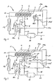
- Fig. 1 shows an internal combustion engine 1, in particular as a direct injection diesel engine, engine running, which has six combustion chambers, which are divided into two combustion chamber groups 2, 3.
- the combustion chambers of the first combustion chamber group 2 bear the designations A1 to A3, the combustion chambers of the second combustion chamber group 3 have the designations B1 to B3.
- Both combustion chamber groups 2 and 3 are each equipped with the individual combustion chambers, not shown fuel injectors equipped, which in turn are summarized according to the combustion chamber groups 2 and 3 to injector groups 4 and 5.
- Both injector groups 4 and 5 can be actuated by an engine control unit 11 via control lines 14a, 14b.
- the control lines 14a, 14b can be embodied as a bus system, so that a separate response of each fuel injector of the injector groups 4 and 5 via the respectively common control lines 14a, 14b is made possible.
- fresh gas which is made available via a suction line 17, is compressed with fuel, which is introduced via the fuel injectors, and ignited.
- the exhaust gas produced in the combustion chambers A1 to B3 is discharged via a first exhaust manifold 6 assigned to the first combustion chamber group 2 or via a second exhaust manifold 7 assigned to the second combustion chamber group 3.
- the exhaust manifolds are each designed as exhaust branch lines. Both the first exhaust manifold 6 and the second exhaust manifold 7 open into an exhaust gas turbine 8 of an exhaust gas turbocharger, which via a drive shaft 21 with a Compressor 15 of the turbocharger is coupled.
- the compressor 15 sucks fresh air from the environment of the internal combustion engine 1 and compresses it. After passing through an intercooler 13 provided in the intake line 17, the pre-compressed fresh air is made available to the combustion chambers A1 to B3.
- Wastegate Gustav attached which is closed by a pressure relief valve 9, also referred to as wastegate valve, can be closed.
- the pressure relief valve 9 is controlled by the engine control unit 11 via a control line 14c and a e.g. electromechanical actuating device 16 c is actuated and allows a partial exhaust gas flow, which is guided in the exhaust manifold 6, to flow past the exhaust gas turbine 8.
- the overpressure pipe 22 merges with a discharge pipe 23 which leads away from the exhaust gas turbine 8 in front of an exhaust gas aftertreatment unit designed as an exhaust gas converter 10.
- the exhaust gas converter 10 is designed for a selective catalytic reduction according to the SCR method and has a u.a. dependent on the exhaust gas temperature and the exhaust gas flow rate efficiency.
- the exhaust gas converter can be designed in a non-illustrated embodiment of the invention as a soot filter.
- the throttle valve 12 is actuated by the engine control unit 11 via a control line 14d and an example electromechanical actuator 16d and serves to influence the exhaust gas flow through the exhaust pipe 18, which opens behind the exhaust converter 10 in an exhaust pipe 24 leading away from this.
- the throttle valve 12 may in particular as Ring slide valve to be executed, as it is known from exhaust gas turbochargers and turbo brakes ago.
- the efficiency of the exhaust gas converter 10 and thus the quality of the treating exhaust gas with regard to a residual pollutant content and a soot content is essentially determined by the temperature prevailing in the exhaust gas converter 10. This in turn is determined essentially by the temperature, the pressure and the volume flow of the exhaust gas flowing into the exhaust gas converter 10, and by the flow resistance of the exhaust gas converter 10.
- An advantageous operating state of the exhaust gas converter 10 is achieved when exhaust gases with high temperature and low volume flow to flow into the exhaust gas converter 10.
- the exhaust gas temperature, the exhaust gas pressure and the exhaust gas volume flow are dependent on the load state of the internal combustion engine 1.
- the exhaust gas converter 10 In order to nevertheless effect an advantageous exhaust aftertreatment in the exhaust gas converter 10 for such operating states, it is provided to reduce the fuel supply for the second combustion chamber group 3. Since this reduces the throttle losses, which occur in the intake line 17 and are determined by a throttle valve (not shown), the internal combustion engine can be operated with a high degree of efficiency with regard to the utilization of the fuel provided.
- the exhaust gas generated by the first combustion chamber group 2 has a high exhaust gas temperature. The introduced from the first combustion chamber group 2 via the first exhaust manifold 6 and the exhaust gas turbine 8 in the exhaust gas converter 10 exhaust gas is thus suitable despite the low load condition of the internal combustion engine 1 for exhaust aftertreatment.
- the exhaust gas generated by the second, fuel-reduced or fuel-off combustion chamber group 3 can optionally be performed as required via the exhaust manifold 7 of the exhaust turbine 8 and thus subsequently to the exhaust converter 10 or at least partially discharged via the exhaust pipe 18 to the exhaust converter 10 in the exhaust pipe 24 in that the throttle valve 12 is correspondingly activated via the engine control unit 11.
- the supply of the exhaust gas of the second combustion chamber group 3 to the exhaust gas converter 10 can be controlled as a function of the pressure and temperature conditions in the exhaust gas converter 10 and of the respective operating state of the internal combustion engine 1.
- the throttle valve 12 can be adjusted in particular so that in the second exhaust manifold 7 results in a pressure level that is substantially identical to the pressure level of the first exhaust manifold 6.
- a predominant part of the exhaust gas stream from the second combustion chamber group 3 can be conducted into the exhaust gas turbine 8 and from there into the exhaust gas converter 10.
- An adjustment of the throttle valve 12 can be made in particular by means of exhaust pressure sensors, not shown, which are mounted in the first and second exhaust manifold 6 and 7, respectively, and deliver corresponding sensor signals to the engine control unit 11.
- the maximum passage cross-section of the throttle valve 12 may in particular be smaller than an outlet cross-section of the exhaust manifolds 6 and 7, so that even with the throttle valve fully open, an overflow of exhaust gas from the first combustion chamber group 2 into the exhaust pipe 18 can be largely avoided.
- a minimal solution is to provide a valve cross-section which can be switched on and off and which is switched only when idling.
- the throttle valve 12 separates the exhaust pipe 18 gas-tight from the exhaust manifold 7 in the closed state.
- the throttle valve 12 can be opened such that a back pressure remains in the exhaust pipe 18, which is at least slightly higher than the exhaust gas pressure of the first combustion chamber group 2. By more damming the exhaust gas temperature in the exhaust gas converter 10 can be increased if necessary.
- the operation of the throttle valve 12 is independent of the pressure relief valve 9, if this is designed as a conventional, charge pressure-controlled valve. If the pressure relief valve 9 is also opened in the lower load range, advantageously via the engine control unit 11 coordinated actuation of the throttle valve 12 and the pressure relief valve. 9
- the position of the throttle valve 12 is controlled on the basis of measured also for other engine control purposes intake manifold pressure, engine speed and load condition of the internal combustion engine 1.
- a corresponding characteristic map is stored in the engine control unit 11.
- the throttle valve 12 is closed and all combustion chambers A1 to B3 are supplied with fuel in a similar manner.
- Fig. 2 embodiment of the invention shown is a variant of the example of Fig. 1 in that the throttle valve 12 is replaced by a first control valve 19 and a second control valve 20, both of which are provided in the second exhaust manifold 7.
- a first control valve 19 and a second control valve 20 both of which are provided in the second exhaust manifold 7.
- the two control valves 19, 20 allow a controlled or regulated outflow of the coming of the second combustion chamber group 3 exhaust gas in the direction of the exhaust gas turbine 8 and / or in the direction of the exhaust pipe 18.
- the two control valves 19, 20 via control lines 14e, 14f with the Motor control unit 11 connected and can be controlled depending on the operating condition of the internal combustion engine 1 via electromechanical actuators 16e, 16f accordingly.
- a discharge of the exhaust gas flow via the exhaust gas turbine 8 and the downstream exhaust gas converter 10 is provided.
- the exhaust gas flow of the second combustion chamber group 3 via the second exhaust manifold 7 and the opened second control valve 20 is introduced into the exhaust pipe 18 and thus into the exhaust pipe 24 behind the exhaust gas converter 10.
- the control of the control valves 19 and 20 made so that the exhaust gas of the second combustion chamber group 3 can be introduced into the exhaust pipe 18.
- the control valves 19, 20 may be designed as separate flap or slide valves.
- Fig. 3 illustrated embodiment of the invention replaces a switching flap 25, the throttle valve 12 of Fig. 1 and allows a particularly simple switching of the exhaust gas flow the second combustion chamber group 3 between a supply to the exhaust gas turbine 8 or an outflow through the exhaust pipe 18.
- the switching flap 25 is controlled by the engine control unit 11 via a control line 14g.
- FIG. 4 shown embodiment of the invention leads from the second exhaust manifold 7 instead of the bypass converter 18 bypassing the exhaust gas Fig. 1 to 3 an exhaust gas recirculation line 26 from, in which a control valve 20a is provided.
- the return line 26 opens into one of the second combustion chamber group 3 associated suction line section 28b.
- the control valve 19 is as in the example of Fig. 2 .
- a control valve 27 is provided, which depending on the operating state of the internal combustion engine 1, a connection between the Ansaug effet 28a, 28b open or close.
- an exhaust gas stream of the second combustion chamber group 3 can be fed back into the second combustion chamber group 3 and optionally also into the first combustion chamber group 2 during an operating state with a reduced fuel supply compared to the first combustion chamber group 2.
- the exhaust gas flow of the second combustion chamber group 3 can, at least temporarily, also circulate in a closed circuit from the second combustion chamber group 3, the exhaust manifold 7, the return line 26 and the intake line section 28b. As a result, a reduction of charge exchange losses is achieved since the exhaust gas flow of the second combustion chamber group 3 is merely pumped around.
- a pressure box 29 is provided, with which the adjusting device 16, the pressure relief valve 9 additionally in response to the delivery pressure of the fresh air turbine 15 drives.
- each of the exhaust manifolds of the different combustion chamber groups is provided with its own exhaust gas turbine.
Landscapes
- Engineering & Computer Science (AREA)
- Chemical & Material Sciences (AREA)
- Combustion & Propulsion (AREA)
- Mechanical Engineering (AREA)
- General Engineering & Computer Science (AREA)
- Chemical Kinetics & Catalysis (AREA)
- Health & Medical Sciences (AREA)
- Toxicology (AREA)
- Supercharger (AREA)
- Exhaust Gas After Treatment (AREA)
- Exhaust-Gas Circulating Devices (AREA)
- Output Control And Ontrol Of Special Type Engine (AREA)
- Exhaust Silencers (AREA)
- Electrical Control Of Air Or Fuel Supplied To Internal-Combustion Engine (AREA)
Abstract
Claims (9)
- Moteur à combustion interne, comprenant :- au moins un premier et un second groupe (2, 3) formés chacun d'une ou plusieurs chambres de combustion (A1, A2, A3, B1, B2, B3), dans lesquels la ou les chambre(s) de combustion (A1, A2, A3) du premier groupe sont susceptibles d'être alimentées indépendamment de la ou des chambre(s) de combustion (B1, B2, B3) du second groupe avec un carburant (4, 5), et- un circuit de gaz d'échappement avec une première ramification de conduite d'échappement (6) assurant l'échappement hors du premier groupe de chambres de combustion, et une seconde ramification de conduite d'échappement (7) assurant l'échappement hors du second groupe de chambres de combustion, et au moins une unité de post-traitement de gaz d'échappement (10), qui communique à l'entrée avec la première et la seconde ramification de conduite d'échappement, et une conduite de by-pass (18) dérivée depuis la seconde ramification de conduite d'échappement pour contourner l'unité de post-traitement (10) des gaz d'échappement,caractérisé par une unité de commande (11), qui est conçue pour alimenter, dans un mode de fonctionnement du moteur à combustion interne à puissance réduite, le second groupe de chambres de combustion avec une quantité de carburant réduite par rapport au premier groupe de chambres de combustion.
- Moteur à combustion interne selon la revendication 1,
caractérisé par une conduite de recyclage de gaz d'échappement (26) avec une vanne susceptible d'être commandée, qui est dérivée de la seconde ramification de conduite de gaz d'échappement (7) ou d'une conduite de by-pass (18) et qui assure une dérivation pour le contournement de l'unité de post-traitement de gaz d'échappement (10) de la seconde ramification de conduite de gaz d'échappement. - Moteur à combustion interne selon la revendication 1 ou 2,
caractérisé en ce qu'il est prévu une vanne (12, 20, 25) susceptible d'être commandée dans la conduite de by-pass. - Moteur à combustion interne, comprenant :- au moins un premier et un second groupe (2, 3) formés chacun d'une ou plusieurs chambres de combustion (A1, A2, A3, B1, B2, B3), dans lesquels la ou les chambre(s) de combustion (A1, A2, A3) du premier groupe sont susceptibles d'être alimentées indépendamment de la ou des chambre(s) de combustion (B1, B2, B3) du second groupe avec un carburant (4, 5), et- un circuit de gaz d'échappement avec une première ramification de conduite d'échappement (6) assurant l'échappement hors du premier groupe de chambres de combustion, et une seconde ramification de conduite d'échappement (7) assurant l'échappement hors du second groupe de chambres de combustion, et au moins une unité de post-traitement de gaz d'échappement (10), qui communique à l'entrée avec la première et la seconde ramification de conduite d'échappement,caractérisé par une conduite de recyclage de gaz d'échappement (26) avec une vanne susceptible d'être commandée, qui est dérivée de la seconde ramification de conduite de gaz d'échappement (7) ou d'une conduite de by-pass (18) et qui assure une dérivation, pour le contournement de l'unité de post-traitement de gaz d'échappement (10), de la seconde ramification de conduite de gaz d'échappement, et par une unité de commande (11), qui est conçue pour alimenter, dans un mode de fonctionnement du moteur à combustion interne à puissance réduite, le second groupe de chambres de combustion (3) avec une quantité de carburant réduite par rapport au premier groupe de chambres de combustion (2).
- Moteur à combustion interne selon l'une des revendications 1 à 4,
caractérisé en ce qu'il est prévu au moins un turbocompresseur à gaz d'échappement (8), dont la turbine à gaz d'échappement communique à l'entrée avec la première et la seconde ramification de conduite d'échappement. - Moteur à combustion interne selon la revendication 5,
caractérisé en ce qu'il est prévu une vanne (19) susceptible d'être commandée, dans la seconde ramification de conduite d'échappement, avant la turbine de gaz d'échappement et après l'embouchure de la conduite de by-pass. - Moteur à combustion interne selon la revendication 5,
caractérisé en ce qu'il est prévu un clapet d'inversion (25) susceptible d'être commandé, dans la seconde ramification de conduite d'échappement avant la turbine de gaz d'échappement, depuis lequel est dérivée la conduite de by-pass. - Moteur à combustion interne selon l'une des revendications 5 à 7,
caractérisé en ce qu'une conduite de gaz perdus (wastegate) (22) dérivée depuis la première ramification de conduite d'échappement et contournant la turbine de gaz d'échappement est pourvue d'une vanne de gaz perdus (9) susceptible d'être pilotée. - Procédé pour le fonctionnement d'un moteur à combustion interne présentant les caractéristiques de l'une des revendications 1 à 8, dans lequel, dans un mode de fonctionnement à puissance réduite, la quantité de carburant admise au second groupe de chambres de combustion (3) est réduite par rapport au premier groupe de chambres de combustion (2),
caractérisé en ce que les gaz d'échappement sortant du second groupe de chambres de combustion (3), dans des phases de fonctionnement dans lesquelles la quantité de carburant admise au second groupe de chambres de combustion (3) est réduite à une valeur supérieure à zéro, sont menés totalement via une conduite de recyclage de gaz d'échappement (26) avec une vanne susceptible d'être commandée, ladite conduite de recyclage de gaz d'échappement (26) étant dérivée de la seconde ramification de conduite de gaz d'échappement (7) ou d'une conduite de by-pass (18) dérivée depuis la seconde ramification de conduite d'échappement, pour contourner l'unité de post-traitement de gaz d'échappement (10).
Applications Claiming Priority (2)
| Application Number | Priority Date | Filing Date | Title |
|---|---|---|---|
| DE102004032589A DE102004032589B4 (de) | 2004-07-06 | 2004-07-06 | Brennkraftmaschine mit Abgasnachbehandlung und Verfahren zu deren Betrieb |
| PCT/EP2005/007109 WO2006002944A1 (fr) | 2004-07-06 | 2005-07-01 | Moteur thermique dote d'une epuration des gaz d'echappement et procede pour le faire fonctionner |
Publications (2)
| Publication Number | Publication Date |
|---|---|
| EP1763627A1 EP1763627A1 (fr) | 2007-03-21 |
| EP1763627B1 true EP1763627B1 (fr) | 2008-03-26 |
Family
ID=35064981
Family Applications (1)
| Application Number | Title | Priority Date | Filing Date |
|---|---|---|---|
| EP05770233A Expired - Lifetime EP1763627B1 (fr) | 2004-07-06 | 2005-07-01 | Moteur thermique dote d'une epuration des gaz d'echappement et procede pour le faire fonctionner |
Country Status (5)
| Country | Link |
|---|---|
| US (1) | US20080209889A1 (fr) |
| EP (1) | EP1763627B1 (fr) |
| JP (1) | JP2008505281A (fr) |
| DE (2) | DE102004032589B4 (fr) |
| WO (1) | WO2006002944A1 (fr) |
Families Citing this family (29)
| Publication number | Priority date | Publication date | Assignee | Title |
|---|---|---|---|---|
| US7363761B1 (en) * | 2006-10-31 | 2008-04-29 | International Engine Intellectual Property Company, Llc | Exhaust gas throttle for divided turbine housing turbocharger |
| US8758479B2 (en) * | 2007-05-14 | 2014-06-24 | Bhp Billiton Ssm Development Pty Ltd | Nickel recovery from a high ferrous content laterite ore |
| DE102008020406A1 (de) * | 2008-04-24 | 2009-10-29 | Daimler Ag | Abgasturbolader für eine Brennkraftmaschine eines Kraftfahrzeugs und Brennkraftmaschine |
| JP5024459B2 (ja) * | 2008-12-26 | 2012-09-12 | トヨタ自動車株式会社 | 過給機付き内燃機関の排気浄化装置 |
| DE102009004417A1 (de) * | 2009-01-13 | 2010-07-15 | Man Nutzfahrzeuge Aktiengesellschaft | Verfahren zur Nachbehandlung eines Abgasstroms einer mehrzylindrigen Brennkraftmaschine eines Fahrzeuges sowie Abgasnachbehandlungsvorrichtung |
| DE102009004418A1 (de) | 2009-01-13 | 2010-07-15 | Man Nutzfahrzeuge Ag | Verfahren zur Nachbehandlung eines Abgasstroms einer mehrzylindrigen Brennkraftmaschine eines Fahrzeuges sowie Abgasnachbehandlungsvorrichtung |
| KR20120022929A (ko) * | 2009-04-21 | 2012-03-12 | 보르그워너 인코퍼레이티드 | 차량 시스템의 후처리 장치의 활성화 또는 재생 거동을 개선하는 방법 |
| US8347609B2 (en) * | 2009-12-23 | 2013-01-08 | Ford Global Technologies, Llc | Methods and systems for emission system control |
| US8516799B2 (en) | 2009-12-23 | 2013-08-27 | Ford Global Technologies, Llc | Methods and systems for emission system control |
| US8096125B2 (en) * | 2009-12-23 | 2012-01-17 | Ford Global Technologies, Llc | Methods and systems for emission system control |
| US8347611B2 (en) | 2009-12-23 | 2013-01-08 | Ford Global Technologies, Llc | Methods and systems for emission system control |
| US20120023936A1 (en) * | 2010-07-30 | 2012-02-02 | Caterpillar Inc. | Nozzled turbocharger turbine |
| US8042527B2 (en) * | 2010-08-05 | 2011-10-25 | Ford Global Technologies, Llc | Coordination of HP and LP EGR |
| DE102010037971B4 (de) * | 2010-10-05 | 2024-02-01 | Dr. Ing. H.C. F. Porsche Aktiengesellschaft | Abgasnachbehandlungssystem für eine Brennkraftmaschine |
| US8539768B2 (en) * | 2011-05-10 | 2013-09-24 | GM Global Technology Operations LLC | Exhaust bypass system for turbocharged engine with dedicated exhaust gas recirculation |
| EP2764224B1 (fr) * | 2011-10-03 | 2019-04-17 | Volvo Truck Corporation | Système de moteur à combustion interne et procédé permettant d'augmenter la température dans au moins une partie du système de moteur à combustion interne |
| US8943822B2 (en) * | 2012-02-28 | 2015-02-03 | Electro-Motive Diesel, Inc. | Engine system having dedicated auxiliary connection to cylinder |
| US20140352300A1 (en) * | 2013-05-30 | 2014-12-04 | GM Global Technology Operations LLC | Turbocharged engine employing cylinder deactivation |
| US9267450B2 (en) * | 2013-06-10 | 2016-02-23 | Ford Global Technologies, Llc | Method and system for binary flow turbine control |
| DE102013011587A1 (de) * | 2013-07-10 | 2015-01-15 | Daimler Ag | Verbrennungskraftmaschine für einen Kraftwagen sowie Verfahren zum Betreiben einer solchen Verbrennungskraftmaschine |
| EP3077648B1 (fr) * | 2013-11-29 | 2019-01-30 | Volvo Construction Equipment AB | Moteur à combustion interne et procédé de commande de moteur à combustion interne |
| JP6498628B2 (ja) * | 2016-04-01 | 2019-04-10 | ボルボ テクノロジー コーポレイション | 内燃エンジンシステムの少なくとも一部である排ガス後処理システムの温度を上昇させるための方法、ならびにこのような方法を実行する内燃エンジンシステムを備える車両 |
| KR102437227B1 (ko) * | 2017-07-24 | 2022-08-29 | 현대두산인프라코어 주식회사 | 엔진의 배기가스 재순환 시스템 |
| CN111727309B (zh) * | 2018-02-16 | 2021-12-14 | 沃尔沃卡车集团 | 内燃发动机装置 |
| DE102018205769B4 (de) * | 2018-04-17 | 2025-06-18 | Bayerische Motoren Werke Aktiengesellschaft | Brennkraftmaschine mit einer Abgasanlage |
| DE102018205768B3 (de) * | 2018-04-17 | 2019-01-10 | Bayerische Motoren Werke Aktiengesellschaft | Brennkraftmaschine mit einer Abgasanlage |
| JP6666945B2 (ja) * | 2018-04-19 | 2020-03-18 | ボルボ テクノロジー コーポレイション | 内燃エンジンシステムの少なくとも一部における温度を上昇させるための方法ならびにこのようなシステムを備える車両 |
| WO2020001755A1 (fr) * | 2018-06-26 | 2020-01-02 | Volvo Truck Corporation | Procédé amélioré de commande d'un moteur à combustion interne |
| DE102019113743A1 (de) * | 2019-05-23 | 2020-11-26 | Volkswagen Aktiengesellschaft | Brennkraftmaschine mit variabler Auslassventilbetätigung, mehreren Abgasfluten und einem Abgasbypass |
Family Cites Families (14)
| Publication number | Priority date | Publication date | Assignee | Title |
|---|---|---|---|---|
| JPS52107438A (en) * | 1976-03-08 | 1977-09-09 | Nissan Motor Co Ltd | Fuel supply cylinder number control engine |
| DE2912796A1 (de) * | 1979-03-30 | 1980-10-09 | Daimler Benz Ag | Abgassystem fuer vorzugsweise achtzylindrige brennkraftmaschinen |
| JPS5853182B2 (ja) * | 1979-05-07 | 1983-11-28 | 日産自動車株式会社 | 気筒数制御エンジンの排気還流装置 |
| DE3007370C2 (de) * | 1979-09-14 | 1983-03-17 | Nissan Motor Co., Ltd., Yokohama, Kanagawa | Brennkraftmaschine |
| JPS5672234A (en) * | 1979-11-15 | 1981-06-16 | Nissan Motor Co Ltd | Cylinder number controlled engine |
| DE3036508C2 (de) * | 1980-09-27 | 1983-02-24 | Audi Nsu Auto Union Ag, 7107 Neckarsulm | Mehrzylindrige Kolbenbrennkraftmaschine, insbesondere fremdgezündete Einspritzbrennkraftmaschine |
| JPS597747A (ja) * | 1982-07-07 | 1984-01-14 | Nissan Motor Co Ltd | 気筒数制御エンジン |
| JPS5982515A (ja) * | 1982-10-29 | 1984-05-12 | Mazda Motor Corp | デイ−ゼルエンジンの排気ガス浄化装置 |
| US5195323A (en) * | 1991-07-31 | 1993-03-23 | Lorts Anthony R | Turbocharger-exhaust purifier wastegate |
| US5377486A (en) * | 1993-05-17 | 1995-01-03 | Ford Motor Company | Catalytic converter system |
| JP3175491B2 (ja) * | 1994-09-01 | 2001-06-11 | トヨタ自動車株式会社 | 可変気筒エンジンの制御装置 |
| DE19500761C2 (de) * | 1995-01-13 | 1997-12-11 | Daimler Benz Ag | Mehrzylindrische Kolbenbrennkraftmaschine mit mindestens zwei Zylindergruppen und katalytischer Abgasreinigung |
| DE19529835A1 (de) * | 1995-08-12 | 1997-02-13 | Opel Adam Ag | Abgasstrang eines Ottomotors |
| FR2832183B1 (fr) * | 2001-11-13 | 2005-10-28 | Peugeot Citroen Automobiles Sa | Systeme d'aide a la regeneration d'un filtre a particules catalyse dispose dans une ligne d'echappement de moteur diesel de vehicule automobile |
-
2004
- 2004-07-06 DE DE102004032589A patent/DE102004032589B4/de not_active Expired - Fee Related
-
2005
- 2005-07-01 WO PCT/EP2005/007109 patent/WO2006002944A1/fr not_active Ceased
- 2005-07-01 DE DE502005003484T patent/DE502005003484D1/de not_active Expired - Lifetime
- 2005-07-01 JP JP2007519685A patent/JP2008505281A/ja not_active Abandoned
- 2005-07-01 EP EP05770233A patent/EP1763627B1/fr not_active Expired - Lifetime
- 2005-07-01 US US11/631,643 patent/US20080209889A1/en not_active Abandoned
Also Published As
| Publication number | Publication date |
|---|---|
| WO2006002944A1 (fr) | 2006-01-12 |
| US20080209889A1 (en) | 2008-09-04 |
| DE502005003484D1 (de) | 2008-05-08 |
| JP2008505281A (ja) | 2008-02-21 |
| EP1763627A1 (fr) | 2007-03-21 |
| DE102004032589A1 (de) | 2006-02-02 |
| DE102004032589B4 (de) | 2007-05-24 |
Similar Documents
| Publication | Publication Date | Title |
|---|---|---|
| EP1763627B1 (fr) | Moteur thermique dote d'une epuration des gaz d'echappement et procede pour le faire fonctionner | |
| EP1375868B1 (fr) | Dispositif à frein moteur pour un moteur à combustion interne à suralimentation par turbosoufflante | |
| EP2059663B1 (fr) | Procédé et dispositif d'exploitation d'un moteur à combustion interne | |
| DE19837978B4 (de) | Turboaufgeladene Brennkraftmaschine | |
| EP2206899B1 (fr) | Procédé de post-traitement d'un flux de gaz d'un moteur à combustion multi-cylindrique d'un véhicule ainsi que l'installation de post-traitement des gaz d'échappement | |
| EP2206898B1 (fr) | Procédé de post-traitement d'un flux de gaz d'un moteur à combustion multi-cylindrique d'un véhicule ainsi qu'installation de post-traitement des gaz d'échappement | |
| EP1396619A1 (fr) | Système de suralimentation pour un moteur à combustion interne | |
| DE102008044382A1 (de) | Motor mit sequentieller geteilter Reihenturboaufladung | |
| WO2010020323A1 (fr) | Turbocompresseur entraîné par les gaz d'échappement pour un moteur à combustion interne d'un véhicule automobile | |
| WO2008125579A1 (fr) | Moteur à combustion interne suralimenté et procédé | |
| EP3298257B1 (fr) | Système egr avec un filtre à particules et une soupape de décharge | |
| DE202017105126U1 (de) | Abgasleitsystem | |
| DE102004028482B4 (de) | Brennkraftmaschine | |
| DE102005024895A1 (de) | Einlass- und Auslassvorrichtung für eine mehrzylindrige Kraftmaschine | |
| WO2011110314A1 (fr) | Moteur à combustion interne avec suralimentation à deux étages | |
| DE102013201710B4 (de) | Brennkraftmaschine mit Spenderzylinderkonzept | |
| EP4244471B1 (fr) | Moteur à combustion interne pour véhicule motorisé, en particulier pour voiture | |
| DE102017119537A1 (de) | Abgasleitsystem | |
| DE102017111454A1 (de) | Ottomotor mit Partikelfilter und Verfahren zum Betreiben eines Ottomotors | |
| EP1633967A2 (fr) | Moteur a combustion interne avec dispositif de recyclage des gaz d'echappement, et procede associe | |
| WO2011045272A1 (fr) | Moteur à combustion interne avec dispositif à suralimentation et procédé pour faire fonctionner un moteur à combustion | |
| WO2006015814A1 (fr) | Moteur a combustion interne | |
| DE102013008827A1 (de) | Aufgeladene Brennkraftmaschine | |
| DE19849495C2 (de) | Aufgeladene Brennkraftmaschine mit einer die Abgasturbine überbrückenden Umgehungsleitung | |
| DE102016014767A1 (de) | Verfahren zum Betreiben einer Verbrennungskraftmaschine eines Kraftfahrzeugs, sowie Verbrennungskraftmaschine |
Legal Events
| Date | Code | Title | Description |
|---|---|---|---|
| PUAI | Public reference made under article 153(3) epc to a published international application that has entered the european phase |
Free format text: ORIGINAL CODE: 0009012 |
|
| 17P | Request for examination filed |
Effective date: 20061215 |
|
| AK | Designated contracting states |
Kind code of ref document: A1 Designated state(s): DE FR GB IT SE |
|
| RAP1 | Party data changed (applicant data changed or rights of an application transferred) |
Owner name: DAIMLERCHRYSLER AG |
|
| 17Q | First examination report despatched |
Effective date: 20070430 |
|
| DAX | Request for extension of the european patent (deleted) | ||
| RBV | Designated contracting states (corrected) |
Designated state(s): DE FR GB IT SE |
|
| GRAP | Despatch of communication of intention to grant a patent |
Free format text: ORIGINAL CODE: EPIDOSNIGR1 |
|
| RAP1 | Party data changed (applicant data changed or rights of an application transferred) |
Owner name: DAIMLER AG |
|
| GRAS | Grant fee paid |
Free format text: ORIGINAL CODE: EPIDOSNIGR3 |
|
| GRAA | (expected) grant |
Free format text: ORIGINAL CODE: 0009210 |
|
| AK | Designated contracting states |
Kind code of ref document: B1 Designated state(s): DE FR GB IT SE |
|
| REG | Reference to a national code |
Ref country code: GB Ref legal event code: FG4D Free format text: NOT ENGLISH |
|
| REF | Corresponds to: |
Ref document number: 502005003484 Country of ref document: DE Date of ref document: 20080508 Kind code of ref document: P |
|
| REG | Reference to a national code |
Ref country code: SE Ref legal event code: TRGR |
|
| ET | Fr: translation filed | ||
| PLBE | No opposition filed within time limit |
Free format text: ORIGINAL CODE: 0009261 |
|
| STAA | Information on the status of an ep patent application or granted ep patent |
Free format text: STATUS: NO OPPOSITION FILED WITHIN TIME LIMIT |
|
| 26N | No opposition filed |
Effective date: 20081230 |
|
| PGFP | Annual fee paid to national office [announced via postgrant information from national office to epo] |
Ref country code: IT Payment date: 20120725 Year of fee payment: 8 |
|
| PG25 | Lapsed in a contracting state [announced via postgrant information from national office to epo] |
Ref country code: IT Free format text: LAPSE BECAUSE OF NON-PAYMENT OF DUE FEES Effective date: 20130701 |
|
| REG | Reference to a national code |
Ref country code: FR Ref legal event code: PLFP Year of fee payment: 11 |
|
| PGFP | Annual fee paid to national office [announced via postgrant information from national office to epo] |
Ref country code: GB Payment date: 20150727 Year of fee payment: 11 |
|
| PGFP | Annual fee paid to national office [announced via postgrant information from national office to epo] |
Ref country code: FR Payment date: 20150630 Year of fee payment: 11 Ref country code: SE Payment date: 20150731 Year of fee payment: 11 |
|
| PGFP | Annual fee paid to national office [announced via postgrant information from national office to epo] |
Ref country code: DE Payment date: 20150930 Year of fee payment: 11 |
|
| REG | Reference to a national code |
Ref country code: DE Ref legal event code: R119 Ref document number: 502005003484 Country of ref document: DE |
|
| REG | Reference to a national code |
Ref country code: SE Ref legal event code: EUG |
|
| GBPC | Gb: european patent ceased through non-payment of renewal fee |
Effective date: 20160701 |
|
| PG25 | Lapsed in a contracting state [announced via postgrant information from national office to epo] |
Ref country code: FR Free format text: LAPSE BECAUSE OF NON-PAYMENT OF DUE FEES Effective date: 20160801 Ref country code: SE Free format text: LAPSE BECAUSE OF NON-PAYMENT OF DUE FEES Effective date: 20160702 Ref country code: DE Free format text: LAPSE BECAUSE OF NON-PAYMENT OF DUE FEES Effective date: 20170201 |
|
| REG | Reference to a national code |
Ref country code: FR Ref legal event code: ST Effective date: 20170331 |
|
| PG25 | Lapsed in a contracting state [announced via postgrant information from national office to epo] |
Ref country code: GB Free format text: LAPSE BECAUSE OF NON-PAYMENT OF DUE FEES Effective date: 20160701 |