EP1763656B1 - Dispositif et procede d'evaluation de force pour determiner des caracteristiques d'equilibre - Google Patents
Dispositif et procede d'evaluation de force pour determiner des caracteristiques d'equilibre Download PDFInfo
- Publication number
- EP1763656B1 EP1763656B1 EP05733545.7A EP05733545A EP1763656B1 EP 1763656 B1 EP1763656 B1 EP 1763656B1 EP 05733545 A EP05733545 A EP 05733545A EP 1763656 B1 EP1763656 B1 EP 1763656B1
- Authority
- EP
- European Patent Office
- Prior art keywords
- force
- transducers
- support plate
- force transducers
- person
- Prior art date
- Legal status (The legal status is an assumption and is not a legal conclusion. Google has not performed a legal analysis and makes no representation as to the accuracy of the status listed.)
- Expired - Lifetime
Links
- 238000000034 method Methods 0.000 title claims description 22
- 238000011156 evaluation Methods 0.000 claims description 34
- 238000001228 spectrum Methods 0.000 claims description 28
- 238000004364 calculation method Methods 0.000 claims description 18
- 238000005070 sampling Methods 0.000 claims description 16
- 238000005259 measurement Methods 0.000 claims description 14
- 210000003205 muscle Anatomy 0.000 claims description 11
- 229940079593 drug Drugs 0.000 claims description 10
- 239000003814 drug Substances 0.000 claims description 10
- LFQSCWFLJHTTHZ-UHFFFAOYSA-N Ethanol Chemical compound CCO LFQSCWFLJHTTHZ-UHFFFAOYSA-N 0.000 claims description 7
- 230000003068 static effect Effects 0.000 claims description 6
- 238000012544 monitoring process Methods 0.000 claims description 2
- 210000004027 cell Anatomy 0.000 description 30
- 230000005484 gravity Effects 0.000 description 20
- 208000010392 Bone Fractures Diseases 0.000 description 11
- 241000282414 Homo sapiens Species 0.000 description 7
- 208000037265 diseases, disorders, signs and symptoms Diseases 0.000 description 7
- 230000015654 memory Effects 0.000 description 7
- 238000012360 testing method Methods 0.000 description 6
- 230000001186 cumulative effect Effects 0.000 description 5
- 230000004069 differentiation Effects 0.000 description 5
- 230000008901 benefit Effects 0.000 description 4
- 230000037182 bone density Effects 0.000 description 4
- 230000008859 change Effects 0.000 description 4
- 238000001514 detection method Methods 0.000 description 4
- 238000010586 diagram Methods 0.000 description 4
- 208000035475 disorder Diseases 0.000 description 4
- 210000003141 lower extremity Anatomy 0.000 description 4
- 230000009466 transformation Effects 0.000 description 4
- 238000004458 analytical method Methods 0.000 description 3
- 230000037396 body weight Effects 0.000 description 3
- 230000037118 bone strength Effects 0.000 description 3
- 230000006735 deficit Effects 0.000 description 3
- 201000010099 disease Diseases 0.000 description 3
- 230000006870 function Effects 0.000 description 3
- 230000036541 health Effects 0.000 description 3
- 230000005012 migration Effects 0.000 description 3
- 238000013508 migration Methods 0.000 description 3
- 230000003387 muscular Effects 0.000 description 3
- 208000012639 Balance disease Diseases 0.000 description 2
- 206010017076 Fracture Diseases 0.000 description 2
- 230000001133 acceleration Effects 0.000 description 2
- 230000032683 aging Effects 0.000 description 2
- 230000003321 amplification Effects 0.000 description 2
- 230000006399 behavior Effects 0.000 description 2
- 230000006999 cognitive decline Effects 0.000 description 2
- 208000010877 cognitive disease Diseases 0.000 description 2
- 238000000354 decomposition reaction Methods 0.000 description 2
- 238000003745 diagnosis Methods 0.000 description 2
- 230000000694 effects Effects 0.000 description 2
- 230000003993 interaction Effects 0.000 description 2
- 238000003199 nucleic acid amplification method Methods 0.000 description 2
- 210000000056 organ Anatomy 0.000 description 2
- 230000037081 physical activity Effects 0.000 description 2
- 230000008569 process Effects 0.000 description 2
- 238000012545 processing Methods 0.000 description 2
- 230000009257 reactivity Effects 0.000 description 2
- 230000009467 reduction Effects 0.000 description 2
- 230000001953 sensory effect Effects 0.000 description 2
- 210000002023 somite Anatomy 0.000 description 2
- 230000004393 visual impairment Effects 0.000 description 2
- 201000004569 Blindness Diseases 0.000 description 1
- 208000012661 Dyskinesia Diseases 0.000 description 1
- 241000282412 Homo Species 0.000 description 1
- 208000015592 Involuntary movements Diseases 0.000 description 1
- 208000029725 Metabolic bone disease Diseases 0.000 description 1
- 206010049088 Osteopenia Diseases 0.000 description 1
- 208000001132 Osteoporosis Diseases 0.000 description 1
- 208000001164 Osteoporotic Fractures Diseases 0.000 description 1
- 208000037273 Pathologic Processes Diseases 0.000 description 1
- 229910000831 Steel Inorganic materials 0.000 description 1
- 206010047571 Visual impairment Diseases 0.000 description 1
- 208000027418 Wounds and injury Diseases 0.000 description 1
- 230000009471 action Effects 0.000 description 1
- 238000013459 approach Methods 0.000 description 1
- 230000033228 biological regulation Effects 0.000 description 1
- 210000000988 bone and bone Anatomy 0.000 description 1
- 230000000747 cardiac effect Effects 0.000 description 1
- 210000003169 central nervous system Anatomy 0.000 description 1
- 238000006243 chemical reaction Methods 0.000 description 1
- 238000012937 correction Methods 0.000 description 1
- 230000006378 damage Effects 0.000 description 1
- 230000007423 decrease Effects 0.000 description 1
- 230000003247 decreasing effect Effects 0.000 description 1
- 230000002950 deficient Effects 0.000 description 1
- 238000001739 density measurement Methods 0.000 description 1
- 230000001419 dependent effect Effects 0.000 description 1
- 238000013461 design Methods 0.000 description 1
- 238000011161 development Methods 0.000 description 1
- 230000018109 developmental process Effects 0.000 description 1
- 229940039227 diagnostic agent Drugs 0.000 description 1
- 239000000032 diagnostic agent Substances 0.000 description 1
- 230000006872 improvement Effects 0.000 description 1
- 208000014674 injury Diseases 0.000 description 1
- 230000007246 mechanism Effects 0.000 description 1
- 230000017311 musculoskeletal movement, spinal reflex action Effects 0.000 description 1
- 210000002346 musculoskeletal system Anatomy 0.000 description 1
- 230000002232 neuromuscular Effects 0.000 description 1
- 210000002569 neuron Anatomy 0.000 description 1
- 230000007935 neutral effect Effects 0.000 description 1
- NJPPVKZQTLUDBO-UHFFFAOYSA-N novaluron Chemical compound C1=C(Cl)C(OC(F)(F)C(OC(F)(F)F)F)=CC=C1NC(=O)NC(=O)C1=C(F)C=CC=C1F NJPPVKZQTLUDBO-UHFFFAOYSA-N 0.000 description 1
- 230000008506 pathogenesis Effects 0.000 description 1
- 230000036285 pathological change Effects 0.000 description 1
- 230000009054 pathological process Effects 0.000 description 1
- 230000002093 peripheral effect Effects 0.000 description 1
- 230000010254 physiological adaptation Effects 0.000 description 1
- 230000002265 prevention Effects 0.000 description 1
- 230000003449 preventive effect Effects 0.000 description 1
- 230000009979 protective mechanism Effects 0.000 description 1
- 230000004043 responsiveness Effects 0.000 description 1
- 230000035945 sensitivity Effects 0.000 description 1
- 230000036362 sensorimotor function Effects 0.000 description 1
- 230000008054 signal transmission Effects 0.000 description 1
- 238000010183 spectrum analysis Methods 0.000 description 1
- 238000004308 statistical model calculation Methods 0.000 description 1
- 239000010959 steel Substances 0.000 description 1
- 239000005341 toughened glass Substances 0.000 description 1
- 238000012549 training Methods 0.000 description 1
- 238000012546 transfer Methods 0.000 description 1
- 238000000844 transformation Methods 0.000 description 1
- 238000011426 transformation method Methods 0.000 description 1
- 208000029257 vision disease Diseases 0.000 description 1
- 230000002747 voluntary effect Effects 0.000 description 1
- 230000021542 voluntary musculoskeletal movement Effects 0.000 description 1
Images





Classifications
-
- G—PHYSICS
- G01—MEASURING; TESTING
- G01G—WEIGHING
- G01G19/00—Weighing apparatus or methods adapted for special purposes not provided for in the preceding groups
- G01G19/44—Weighing apparatus or methods adapted for special purposes not provided for in the preceding groups for weighing persons
- G01G19/50—Weighing apparatus or methods adapted for special purposes not provided for in the preceding groups for weighing persons having additional measuring devices, e.g. for height
Definitions
- the present invention relates to an apparatus and method for determining balance characteristics.
- the inventive device is used in particular for the quantitative detection of functions and disorders of the motor and sensory balance system in humans.
- US 5,620,003 A describes a platform that can be used to determine cardiac parameters of a person standing on the platform.
- the signal transmission is done by means of several signal converter whose signals can be added.
- the signal converters can be piezosensors.
- the signals can be converted by means of an A / D converter and evaluated via an FFT.
- the FR 2 690 613 A describes a force evaluation device having a plurality of independent plates. Per single plate more than one force sensor can be provided. It can be done a Furier transformation or a so-called chaos analysis.
- the US 4,195,643 A describes a force evaluation device that can be used to evaluate muscle movements of patients.
- Systems with one or more pedestal plates to which multiple force sensors are associated may be used.
- the signals of the individual sensors can be added together and evaluated by means of Furier transformations.
- US 2001/056249 A a force evaluation device with force sensors between bottom and cover plates.
- the platform is used in particular for the determination of balance problems.
- An FFT can be used for evaluation.
- the balance of a person in the state is ensured by the harmonious interaction of the motor system and sensors of the human musculoskeletal system and by special functions of the central nervous system, the spinal motor and the supraspinal motor system.
- the balance in standing is currently being tested by various tests that allow only a subjective assessment by the observer, possibly with the aid of a stopwatch.
- Disturbances in the spinal motor and supraspinal motor system are on the one hand due to illness or injury, on the other hand, they are subject to aging processes. All components that provide a secure footing or more purposeful voluntary and involuntary movements may be affected.
- the fine regulation of the lower extremity muscle groups, especially the foot flexors and foot extensors mainly helps to maintain a stable standing posture.
- osteopenia and osteoporosis are currently performed using bone density measurements and does not consider the causes, pathogenesis or bone strength.
- the development of osteoporotic fractures in postmenopausal women is mainly attributed to decreased bone strength.
- the bone density is therefore determined as a preventive measure.
- more than 80% of the probability of fracture depends on other factors. These are u.a. Factors include: lower limb strength or lower limb muscle performance, balance disorders, walking disorders, medication intake, alcohol and other drugs, cognitive decline in relation to the environment, and vision loss. These factors are partly health impairments. At present they are only determined in qualitative form (anamnesis).
- the risk of a fall of a person is closely linked to the sensorimotor control of the body's center of gravity. Numerous endogenous and exogenous factors influence the performance of sensorimotor function.
- the spinal and supraspinal motor systems may be affected at various points by pathological processes or changes due to aging. You can thus have performance deficits that are associated with an increased risk of falls. It expresses to what extent and at which speed muscle power can be activated in order to correct a deflection of the center of gravity in the direction of an unstable state and to avoid a fall.
- the epidemiological data allow conclusions about the frequency of bone fractures on the underlying mechanical properties of the bones and other factors associated with them.
- the bone density as surrogate parameter or replacement parameter for the bone strength
- a relation to the probability of bone fractures can be derived.
- Statistical model calculations based on large epidemiological studies show that bone density can only explain the probability of a fracture by about 15%. If a bone fracture is not primarily the result of a unavoidable and unforeseen force, then by means of the protective mechanism of the fall prevention or the mechanism of a suitable evasion reaction of an external disturbance can be counteracted. A measure of the ability to do so should be derived in principle from a simple system of equilibrium analysis.
- tandem stand test is the ability tested, with feet arranged in front of each other (heel of one foot immediately in front of the toe of the other foot arranged or arrangement of both feet on a straight line) to be able to hold the stand for about 10 s, without making a lunge.
- the force evaluation device has exactly three force transducers or force sensors arranged in one plane (force transducer plane). With these force transducers a rigid, walkable carrier plate is coupled. If a pressure force (for example weight of a person) is exerted on this support plate on the side facing away from the load cells during a time interval (measurement interval), the mutually decoupled force transducers receive time-resolved forces transmitted to the load cells via the support plate and resulting from the pressure force.
- An evaluation unit is connected to the force transducers on the signal output side. The latter has a power spectrum calculation unit with which the power spectrum of a total signal formed from the sum of the output signals of the exactly three force transducers can be calculated.
- the force evaluation device can have a differentiation unit with which the time derivative of the overall signal just described can be calculated and with which further characteristics can be derived from the calculated time derivative.
- a differentiation unit with which the time derivative of the overall signal just described can be calculated and with which further characteristics can be derived from the calculated time derivative.
- load cells which are arranged in the force transducer level in the form of a triangle. Particularly preferably, this is an arrangement in the form of an equilateral triangle.
- the force evaluation device on the side facing away from the carrier plate adjacent to the force transducer on a bottom plate.
- the unit of support plate and bottom plate, between which then the load cells are arranged, is thus stable and robust and easy erectable on a flat bottom surface.
- the evaluation unit with the force transducers signal output side connected operational amplifier, with which the output signal of the force transducer can be amplified.
- Signal output side after the operational amplifiers the evaluation then has an analog-to-digital converter, with which the amplified analog signals at the output of the operational amplifier can be converted into a digital signal.
- the described embodiment variant then has a computer, in particular a personal computer PC, to which the digital signals can be transmitted for evaluation.
- the power spectrum calculation unit and the differentiation unit of the evaluation unit can be components of the computer in the variant described.
- FIG. 1A shows a sectional view through a force evaluation device according to the invention perpendicular to the Kraftaufrichebene.
- FIG. 1B shows a plan view of this force evaluation device or a view of the force transducer level.
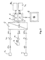
- the evaluation unit for evaluating the detected forces is in the block diagram of FIG. 2 (see below).
- the measuring unit and the evaluation unit communicate with each other to exchange data.
- the force evaluation device has a rigid, flat, triangular base plate 3. This is made in the present case of steel.
- the triangular shape is defined by an equilateral triangle with an edge length of 60 cm here. The three triangle tips of the bottom plate are rounded.
- the bottom plate 3 has a thickness (perpendicular to the force transducer plane, ie in the z-direction) of 1 cm.
- the bottom plate is arranged in the case shown above a flat bottom surface B and adjacent thereto.
- three force transducers 1a to 1c (hereinafter alternatively referred to as force sensors or load cells) are arranged in the region of the triangle tips.
- the load cells are bolted to the bottom plate 3, but can for example also be glued.
- the three load cells are arranged in a plane (force transducer level) in the form of an equilateral triangle.
- Each load cell is in this case in the region of the triangular tip of the bottom plate slightly (a few cm) from the peripheral edge of the bottom plate spaced, arranged so that the equilateral triangle, which is formed by the three load cells 1a to 1c, has a side length of about 55 cm.
- a likewise formed in the form of an equilateral triangle support plate 2 is arranged above the three load cells 1a to 1c.
- the carrier plate is a shatter-proof, by a person with a weight up to about 200 kg enterable plate, which slip-proof on the three load cells 1a to 1c is launched.
- the rigid, enterable carrier plate 2 has parallel to the Kraftaufrichebene (which is formed by the arrangement of the three force transducer 1) the same shape and size as the bottom plate 3.
- the carrier plate 2 is here a double toughened glass plate according to DIN 1249 a thickness of 16 mm.
- the transducer axes of the three force transducers 1a to 1c are arranged parallel to one another and in the z-direction or perpendicular to the force transducer plane (x-y-plane).
- the transducer axis of a force transducer is defined by the fact that a force or force component acting on the force transducer 1 along this axis is determined or detected by the force transducer.
- the force transducers 1a to 1c arranged between the base plate 3 and the carrier plate 2 are commercially available load cells.
- load cells are used which have a maximum load of 2000 N or 2 kN for a deformation or a nominal measuring path in the pick-up axis direction of 0.2 mm.
- the load cells used have an accuracy class of ⁇ 0.1% with respect to the detected forces.
- the nominal characteristic value (sensitivity) or the signal voltage of the three load cells is 2 mV / V each.
- the load cells "K-450" of the company "ATP Messtechnik + Waagen" are used.
- FIG. 1B is also the tandem stand T sketched that a person standing on the support plate 2 should take during the detection and evaluation of the forces exerted on the force transducer 1a to 1c forces.
- FIG. 2 shows a block diagram of the force evaluation device of the invention FIG. 1 in which both the load cells of the FIG. 1 shown measuring unit as well as the signal evaluation downstream components 4, 5, 6, 7, 8 of the evaluation unit are visible.
- Each of the load cells 1a to 1c is an operational amplifier 4a to 4c signal output side downstream.
- the operational amplifiers amplify the analog signals by a factor of 150 or 300 (however, other amplifier factors may be used).
- the three now amplified analog signals VA1a to VA1c are supplied via suitable signal lines to the operational amplifiers 4 downstream analog-to-digital converter ADC 5 with three input channels.
- the ADC 5 has its output connected to a control computer (PC) 6.
- the ADC is the type "miniLAB 1008" from Measurement Computing Corporation.
- the operational amplifiers 4 and the ADC 5 are arranged between the bottom plate 3 and the carrier plate 2 within the triangle formed by the three load cells 1a to 1c (in FIG FIG. 1 Not shown). This has the advantage that the data lines for transmitting the signals A1a to A1c or VA1a to VA1c are short.
- the ADC output signals then become transferred via a USB cable via a USB port of the PC 6 in the latter.
- the ADC 5 may also be formed as a multi-channel data acquisition card, which is arranged within the computer 6.
- the ADC 5 thus generates from the electrical voltages, which are generated due to the pressure load of the support plate 2 from the load cells 1 a to 1 c, USB-compliant signals which are fed to the control computer 6.
- the measured values of the load cells 1 or the corresponding voltages are hereby digitized in real time by the ADC 5.
- the control computer 6 can also control the time window of the opening of the measuring channels of the ADC 5 via associated auxiliary software.
- the measuring interval over which the force values detected by means of the force sensors 1 are digitized and evaluated is determined.
- the ADC 5 thus generates measurement time series of the three load cells 1a to 1c, which are available for further processing in the computer 6.
- the power supply of the ADC is done here with a switching power supply, the stabilized 12 V outputs.
- the power spectrum calculation unit 7 and the differentiating unit 8 are components of the computer 6. Both units 7, 8 each have a computing unit and a memory including a command sequence 7a, 8a stored therein.
- the memory and the arithmetic unit of the power spectrum calculation unit 7 (also referred to as LB in the figure) and the differentiating unit 8 (also denoted by D in the figure) are identical here. Alternatively, however, separate memories and / or arithmetic units may also be used for both units become.
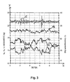
- the three measured value time series acquired and digitized by means of the three load cells 1, three operational amplifiers 4 and the ADC 5 over the measuring interval are added in the computer 6 (see FIG FIG. 3 ).
- the power spectrum calculation unit 7 calculates the power spectrum of the overall signal. This is done with the instruction sequence 7a stored in the memory of the power spectrum calculation unit 7.
- the differentiating unit 8 calculates from the total signal the time derivative of the total signal in the measuring interval. From this time derivative, then, as described below, further parameters are calculated.
- the calculation of the differentiating unit 8 takes place with the instruction sequence 8a stored in the memory of the differentiating unit 8.
- the two described command sequences are generated or compiled here using the Delphi programming language. However, other programming languages such as C ++ may be used.
- the operating system used in the present case is Windows XP.
- the results of the calculation may be graphically displayed by the computer 6 on the output unit 9 (for example, a screen).
- the described programs or command sequences can also check the calibrated setpoint values of the sensors 1.
- the sampling rate is 100 Hz (in general: at least 50 Hz), the amplification factors as already described 150 or 300 and the measurement duration 10 s.
- other values may be used.
- FIG. 3 shows the computer 6 calculates the sum of the measured values over the time interval from the individual sampled or measured force measured values of the three load cells 1a to 1c at each sampling time in the measuring interval. This results in the total signal G.
- the first characteristic is now the over the time interval (here 10 s, x-axis in FIG. 3 ) averaged total signal determined.
- This mean value of G is a measure of the mass of the body or of the person on the support plate 2.
- FIG. 4 shows FIG. 4 the power spectrum or power spectrum of the overall signal G from FIG. 3 .
- This power spectrum was calculated by means of the power spectrum calculation unit together with the instruction sequence 7a stored therein.
- the basis of the calculation here is a sampling of the analog output signals VA1a to VA1c by the ADC 5 with a sampling rate of at least 50 Hz. In the present case, sampling was carried out at 100 Hz. The minimum value of 50 Hz corresponds to approximately four times the expected frequencies. At such a sampling rate, low force impulses appear, predominantly through the flexor group of the foot musculature and the peroneus muscles the person standing on the carrier plate 2 during the measuring interval are generated.
- the time series G of the force sum of the three sensors 1a to 1c was subjected to a frequency decomposition.
- this was carried out by means of the Fourier transformation method, here in particular the fast Fourier transformation FFT.
- FFT fast Fourier transformation
- a frequency decomposition can also be carried out with the maximum entropy method by means of the power spectrum calculation unit 7 (for example, for the method of maximum entropy and fast Fourier transformation, see Numerical Recipes "in Pascal: The Art of Scientific Computing, William H. Price, Brian P. Flannery, Saul A. Teukolsky, William T. Vetterling, Cambridge University Press, 1989 ).
- the method of maximum entropy offers the advantage of a higher resolution.
- the power spectrum calculation unit 7 thus performs an analysis of the frequency components in the force pulses (spectral analysis) by means of the program code 7a.
- the determined power spectrum or power spectrum is in FIG. 4 in the range from 0 Hz to 30 Hz. As the figure shows, muscle action is mainly in the range of 0 to about 13 Hz.
- the power spectrum is then further evaluated by means of the unit 7. Arithmetic or geometric mean values of the occurring frequencies or average frequencies are determined. These allow a statement about the reactivity of the subject: the higher the average frequencies are, the higher the responsiveness of the person.
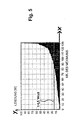
- FIG. 5 shows an example of the characteristics determined by means of the differentiating unit 8 and the program sequence 8a.
- Sampling rate here 100 Hz, generally according to the invention sampling rates between 50 and 250 Hz to use
- total signal G are numerically differentiated by time.
- the numerical differentiation can hereby, as described briefly below, be carried out by means of a simplified support point method. For this purpose, first a base number is determined. This is preferably between 5 and 15 points. In the present case 10 bases were used. Starting from each measured value or sample value in FIG.
- summation curve G is the local slope between this measured value and the measured value to the measured value by said support point number temporally following measured value determined. If the slope determined by the two measured values lying apart from one another is positive, then the two measured values by means of which the slope is determined are offset in the total sum curve G by one measured value in time (that is, one sample later) Measured values are used to determine the slope) and the local slope is determined again. If this local slope is greater than that determined in the previous step, then the method is continued, ie the measured value pair, by means of which the slope is determined, is in each case shifted backwards by one further measured value. The The method then stops when the locally determined slope no longer increases, decreases again or becomes negative.
- the pulse peak values described are now a measure of the peak power occurring at the corresponding time, which is exerted by the person standing on the carrier plate 2 for maintaining the balance.
- the Performance is physically defined as the work done per unit of time.
- the work results from the force against the "spring travel" of the force transducer 1.
- the differentiation unit 8 or program 8a can filter out the local maximum pulse peak powers of the individual positive force increases in the described manner. From these pulse peak power values whose spectrum, as in FIG. 5 shown, sorted, then the average peak pulse power value can be calculated.
- the necessary power required to bring a body back to its neutral center of gravity or its equilibrium position naturally also depends on the body mass.
- the ratio of the mean pulse peak power value and the time average of the cumulative curve G over the measurement interval is calculated as a further parameter.
- the said ratio or division of the mean peak pulse power value by the body mass thus gives the average pulse peak power per body mass (specific mean pulse peak power). This value is then comparable regardless of the body mass of the individual examined.
- the mean peak pulse power (horizontal line) or the specific mean pulse peak power (mean pulse peak power per body mass) calculated therefrom is a measure of the effort and / or the effort that a person standing on the carrier plate 2 has to spend to maintain the balance.
- the calculation of another characteristic is in figure 6 shown.
- This figure outlines how, by means of the signal differences of the three decoupled load cells 1a to 1c, a calculation of the position of the dynamic center of gravity of the person standing on the carrier plate 2 is determined.
- the dynamic center of gravity can be composed of a static portion resulting from the mass of persons (static center of gravity of the person) and of a portion resulting from the force exerted by the person on the carrier plate 2 by means of muscular forces.
- an orthogonal coordinate system is first selected whose xy plane corresponds to the force transducer plane K. The xy plane of the coordinate system is thus in the plane formed by the three contact points of the load cells 1a to 1c.
- the change in the location of the dynamic center of gravity or the track of the center of gravity of the force vector from the body weight and the interaction of the muscular forces (the latter represents the dynamic center of gravity) is now calculated over the measuring interval or the detected time interval.
- the calculation is done here for the projection of the dynamic center of gravity on the xy plane or the force transducer plane.
- m i denotes the measured value of the ith force transducer at the time of measurement
- m tot denotes the sum over the measured values of the three force transducers at this time
- r i denotes the position vector of the ith force transducer in the orthogonal coordinate system shown.
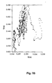
- FIG. 7 shows three examples of the area swept by the migration of the center of gravity (x, y) in the plane K during the measurement interval.
- the evaluation unit here by means of the PC
- the swept area is recorded quantitatively.
- FIG. 7A In the case shown, the area is about 5.5 * 10.7 cm 2 .
- FIG. 7B As shown, the area is only 1.4 * 2.5 cm 2 .
- the swept area In FIG. 7C the swept area is about 28.1 * 26 cm 2 .
- the correspondingly swept area is now a measure of the ability of each person (A or B or C) to keep the balance on the support plate 2 during the measurement interval. The smaller the swept area, the better this ability is.
- the swept area or the metric extent in the xy-diagram will, to a first approximation, be independent of the age of the person examined, but highly dependent on other influences, such as, for example, taking medication, ingesting alcohol and / or drugs , Disturbances in keeping the balance in general as well as after apoplectic insult or diseases of the organ of balance.
Landscapes
- Physics & Mathematics (AREA)
- General Physics & Mathematics (AREA)
- Measurement Of The Respiration, Hearing Ability, Form, And Blood Characteristics Of Living Organisms (AREA)
- Force Measurement Appropriate To Specific Purposes (AREA)
Claims (11)
- Dispositif d'analyse des forces avec lequel des forces s'exerçant sur un transducteur de force peuvent être déterminées et analysées avec une résolution temporelle, comprenant précisément trois transducteurs de force (1) agencés sous forme d'un triangle dans un plan de transducteurs de force comprenant, respectivement, une sortie de signaux,
une plaque de support (2) accessible, rigide, couplée aux transducteurs de force (1), les transducteurs de force (1) étant agencés sur un côté de la plaque de support (2) de manière adjacente à celle-ci, les forces résultant d'une force de pression s'exerçant sur la plaque de support (2) au niveau des transducteurs de force (1) pouvant être détectées par les transducteurs de force (1) avec une résolution temporelle, et les signaux de sortie des transducteurs de force (1) pouvant respectivement être échantillonnés à un taux d'échantillonnage supérieur à 50 Hz et inférieur à 250 Hz, et
une unité d'analyse (4, 5, 6, 7) avec laquelle les transducteurs de force (1) sont raccordés du côté de la sortie de signaux et qui présente une unité de calcul de spectre des puissances (7) avec laquelle le spectre des puissances du signal global formé à partir de la somme des signaux de sortie des précisément trois transducteurs de force (1) peut être calculé,
avec l'unité d'analyse (4, 5, 6, 7), à partir des signaux de sortie des transducteurs de force (1), la position momentanée, projetée dans le plan des transducteurs de force, du centre de gravité dynamique d'une personne exerçant une pression sur la plaque de support du côté opposé aux transducteurs de force et la surface recouverte depuis cette position ou son trajet de déplacement dans le plan des transducteurs de force pendant un intervalle de temps pouvant être déterminées, et
avec l'unité d'analyse (4, 5, 6, 7), le spectre de puissance calculé pouvant être analysé au niveau des fréquences qu'il contient en ce que la moyenne arithmétique et/ou géométrique des fréquences qu'il contient est(sont) calculée(s). - Dispositif d'analyse des forces selon la revendication précédente,
caractérisé par
une plaque de fond (3) agencée sur le côté opposé à la plaque de support (2) de manière adjacente aux transducteurs de force (1). - Dispositif d'analyse des forces selon l'une quelconque des revendications précédentes, caractérisé
en ce qu'au moins un des transducteurs de force (1) est un capteur piézoélectrique. - Procédé d'analyse des forces avec lequel des forces s'exerçant sur des transducteurs de force peuvent être déterminées et analysées avec une résolution temporelle,
précisément trois transducteurs de force (1) comprenant, respectivement, une sortie de signaux étant agencés sous forme d'un triangle dans un plan de transducteurs de force et sur un côté d'une plaque de support (2) accessible, rigide, de manière adjacente à celle-ci et sont couplés à la plaque de support (2) de telle sorte que les forces résultant d'une force de pression s'exerçant sur la plaque de support (2) au niveau des transducteurs de force (1) peuvent être détectées par les transducteurs de force (1) avec une résolution temporelle,
la plaque de support (2) étant soumise à une pression sur le côté opposé aux transducteurs de force (1) au cours d'un intervalle de temps en ce qu'une personne monte sur la plaque de support et/ou se tient sur la plaque de support,
les signaux de sortie des transducteurs de force (1) étant, respectivement, échantillonnés à un taux d'échantillonnage supérieur à 50 Hz et inférieur à 250 Hz,
pour l'intervalle de temps, un signal global intégrant une résolution temporelle étant formé à partir de la somme des signaux de sortie des précisément trois transducteurs de force (1) résultant du fait de la pression exercée sur les transducteurs de force (1),
le spectre de puissance du signal global étant calculé et analysé au niveau des fréquences qu'il contient en ce que la moyenne arithmétique et/ou géométrique des fréquences qu'il contient est(sont) calculée(s), et
à partir des signaux de sortie des transducteurs de force (1), au cours de l'intervalle de temps, la position momentanée, projetée dans le plan des transducteurs de force, du centre de gravité dynamique de la personne et la surface recouverte depuis cette position ou son trajet de déplacement dans le plan des transducteurs de force pendant cet intervalle de temps étant déterminées. - Procédé d'analyse des forces selon la revendication précédente,
caractérisé
en ce que la moyenne temporelle du signal global au cours de l'intervalle de temps est formée pour la détermination de la pression moyenne exercée sur la plaque de support. - Procédé d'analyse des forces selon l'une des deux revendications précédentes,
caractérisé
en ce que le centre de gravité dynamique se compose d'une part statique résultant de la masse de la personne et d'une part résultant de la force exercée sur la plaque de support par la personne au moyen de forces musculaires. - Procédé d'analyse des forces selon l'une quelconque des trois revendications précédentes, caractérisé
en ce que la position momentanée du centre de gravité dynamique est calculée selon

r i le vecteur de position du i-ième transducteur de force dans un système de coordonnées orthogonal. - Procédé d'analyse des forces selon l'une quelconque des quatre revendications précédentes, caractérisé
en ce que le rapport entre la surface recouverte déterminée pour une première personne et la surface recouverte déterminée pour une deuxième personne non identique à la première personne est calculé. - Procédé d'analyse des forces selon l'une quelconque des cinq revendications précédentes, caractérisé
en ce que le spectre de puissance du signal global est calculé au moyen de la transformation de Fourier ou au moyen de la méthode de l'entropie maximale. - Procédé d'analyse des forces selon l'une quelconque des six revendications précédentes, caractérisé
en ce que le spectre de puissance calculé est analysé au niveau des fréquences qu'il contient en ce que des maximas sont calculés dans le spectre de puissance. - Utilisation d'un dispositif d'analyse des forces ou d'un procédé d'analyse des forces selon l'une quelconque des revendications précédentes pour la détermination ou la surveillance de l'aptitude à conduire de personnes, pour la détermination de l'influence de l'alcool ou de drogues sur les capacités motrices de personnes ou pour la détermination de valeurs caractéristiques pour la forme physique de personnes.
Applications Claiming Priority (2)
| Application Number | Priority Date | Filing Date | Title |
|---|---|---|---|
| DE102004032398 | 2004-07-03 | ||
| PCT/DE2005/000467 WO2006005279A1 (fr) | 2004-07-03 | 2005-03-15 | Dispositif et procede d'evaluation de force pour determiner des caracteristiques d'equilibre |
Publications (2)
| Publication Number | Publication Date |
|---|---|
| EP1763656A1 EP1763656A1 (fr) | 2007-03-21 |
| EP1763656B1 true EP1763656B1 (fr) | 2013-09-25 |
Family
ID=34965469
Family Applications (1)
| Application Number | Title | Priority Date | Filing Date |
|---|---|---|---|
| EP05733545.7A Expired - Lifetime EP1763656B1 (fr) | 2004-07-03 | 2005-03-15 | Dispositif et procede d'evaluation de force pour determiner des caracteristiques d'equilibre |
Country Status (6)
| Country | Link |
|---|---|
| US (1) | US20080188775A1 (fr) |
| EP (1) | EP1763656B1 (fr) |
| JP (1) | JP2008504080A (fr) |
| CN (1) | CN1985155A (fr) |
| DE (1) | DE112005002192A5 (fr) |
| WO (1) | WO2006005279A1 (fr) |
Families Citing this family (23)
| Publication number | Priority date | Publication date | Assignee | Title |
|---|---|---|---|---|
| JP4749897B2 (ja) * | 2006-03-15 | 2011-08-17 | ニッタ株式会社 | 歩行訓練支援装置 |
| DE102006032081B4 (de) * | 2006-07-11 | 2013-09-26 | Julius-Maximilians-Universität Würzburg | Ergometer, Laufschuh und Fahrradpedal |
| JP4805070B2 (ja) * | 2006-09-07 | 2011-11-02 | ニッタ株式会社 | 転倒危険度判定装置 |
| US8152744B2 (en) * | 2008-03-25 | 2012-04-10 | Comfort Lab. Inc. | Shoe or insole fitting navigation system |
| JP5938214B2 (ja) * | 2008-09-12 | 2016-06-22 | コーニンクレッカ フィリップス エヌ ヴェKoninklijke Philips N.V. | 転倒検出システム |
| US9489600B2 (en) * | 2009-04-24 | 2016-11-08 | Commissariat A L'energie Atomique Et Aux Energies Alternatives | System and method for determining the activity of a mobile element |
| JP5426964B2 (ja) * | 2009-08-26 | 2014-02-26 | パナソニック株式会社 | 健康測定装置 |
| CN101975607B (zh) * | 2010-11-15 | 2013-09-04 | 黑龙江省水利科学研究院 | 电子秤 |
| DE102012101054A1 (de) * | 2012-02-09 | 2013-08-14 | T & T Medilogic Medizintechnik Gmbh | Vorrichtung zur Fußdiagnostik |
| DE102012101049B4 (de) * | 2012-02-09 | 2015-06-18 | T & T Medilogic Medizintechnik Gmbh | Vorrichtung zur Fußdiagnose |
| JP6183827B2 (ja) * | 2013-03-14 | 2017-08-23 | 株式会社タニタ | 運動機能評価装置及び運動機能評価方法 |
| CN106137132B (zh) * | 2013-03-14 | 2019-05-07 | 株式会社百利达 | 运动机能评价装置及方法、运算装置及方法 |
| CN103251411A (zh) * | 2013-04-08 | 2013-08-21 | 杭州电子科技大学 | 一种基于复杂度的压力中心非线性特征提取方法 |
| US20150099245A1 (en) * | 2013-10-01 | 2015-04-09 | Universite Du Quebec A Chicoutimi | Method for monitoring an activity of a cognitively impaired user and device therefore |
| CN112043281B (zh) | 2015-06-30 | 2024-08-02 | 兹布里奥有限公司 | 使用机器学习算法识别跌倒风险 |
| CN105286874B (zh) * | 2015-11-03 | 2018-06-19 | 长安大学 | 一种用于预测老年人跌倒风险的系统及方法 |
| CN105708465B (zh) * | 2016-04-19 | 2019-12-13 | 东华大学 | 一种可探知脊椎状态的家用秤及其使用方法 |
| CN107643132A (zh) * | 2016-07-22 | 2018-01-30 | 上海域丰传感仪器有限公司 | 一种密封压陶瓷平膜压力传感器 |
| WO2018066422A1 (fr) * | 2016-10-07 | 2018-04-12 | パナソニックIpマネジメント株式会社 | Dispositif d'évaluation de la fonction cognitive, procédé d'évaluation de la fonction cognitive et programme |
| CN107967931B (zh) * | 2017-12-29 | 2024-01-26 | 新绎健康科技有限公司 | 身体平衡数据采集器 |
| CN108309236B (zh) * | 2018-01-15 | 2021-08-27 | 新绎健康科技有限公司 | 人体平衡评估方法及系统 |
| CN111977233A (zh) * | 2019-05-22 | 2020-11-24 | 深圳市瑞微智能有限责任公司 | 一种物料出入库定位方法、装置及系统 |
| CN111776247A (zh) * | 2020-06-04 | 2020-10-16 | 核工业北京地质研究院 | 一种滑翔无人机发射系统推力测量系统及方法 |
Citations (1)
| Publication number | Priority date | Publication date | Assignee | Title |
|---|---|---|---|---|
| DE10151361A1 (de) * | 2001-10-22 | 2003-04-30 | Novotec Medical Gmbh | Vorrichtung zur Erfassung und Auswertung der Motorik des menschlichen Bewegungsapparates |
Family Cites Families (36)
| Publication number | Priority date | Publication date | Assignee | Title |
|---|---|---|---|---|
| US3169022A (en) * | 1962-04-10 | 1965-02-09 | Elwood A Kretsinger | Means for indicating the distribution of a golfer's weight at the instant of ball impact |
| US3712294A (en) * | 1970-07-24 | 1973-01-23 | J Muller | Method and apparatus for measuring human reaction |
| US3894437A (en) * | 1974-01-10 | 1975-07-15 | John L Hagy | Method of and means for dynamic gait analysis |
| US4195643A (en) * | 1976-12-27 | 1980-04-01 | Massachusetts Institute Of Technology | Diagnostic force analysis system |
| US4267728A (en) * | 1978-07-04 | 1981-05-19 | Manley Michael T | Apparatus for analyzing the forces acting on a human foot |
| US4394865A (en) * | 1980-05-22 | 1983-07-26 | Belorussky Nauchnoissledovatelsky Institut Kardiologii | Apparatus for determining levels of physical loads |
| US4830024A (en) * | 1982-08-16 | 1989-05-16 | Nashner Lewis M | Apparatus and method for determining the presence of vestibular perilymph fistulae and other abnormal coupling between the air-filled middle ear and the fluid-filled inner ear |
| US4631676A (en) * | 1983-05-25 | 1986-12-23 | Hospital For Joint Diseases Or | Computerized video gait and motion analysis system and method |
| US4600016A (en) * | 1985-08-26 | 1986-07-15 | Biomechanical Engineering Corporation | Method and apparatus for gait recording and analysis |
| US5476103A (en) * | 1991-10-10 | 1995-12-19 | Neurocom International, Inc. | Apparatus and method for assessment and biofeedback training of leg coordination and strength skills |
| WO1993006779A1 (fr) * | 1991-10-10 | 1993-04-15 | Neurocom International, Inc. | Appareil et procede de caracterisation de la demarche |
| FR2690613B3 (fr) | 1992-04-29 | 1994-07-13 | Kohen Raz Reuven | Procede de posturographie tetra-ataxiametrique, systeme pour sa mise en óoeuvre et dispositif multicapteur associe. |
| AU4963193A (en) * | 1992-09-15 | 1994-04-12 | Increa Oy | Method and apparatus for measuring quantities relating to a person's cardiac activity |
| US5388591A (en) * | 1992-12-09 | 1995-02-14 | Trustees Of Boston University | Method and apparatus for analyzing the human postural control system |
| US6067986A (en) * | 1993-10-29 | 2000-05-30 | Kluger; Alan | Method and apparatus employing motor measures for early diagnosis and staging of dementia |
| US5885229A (en) * | 1995-07-19 | 1999-03-23 | Nippon Telegraph & Telephone Corp. | Walking pattern processing method and system for embodying the same |
| JPH09120464A (ja) * | 1995-08-21 | 1997-05-06 | Matsushita Electric Ind Co Ltd | リハビリテーション支援装置 |
| US6231527B1 (en) * | 1995-09-29 | 2001-05-15 | Nicholas Sol | Method and apparatus for biomechanical correction of gait and posture |
| US5919150A (en) * | 1996-07-22 | 1999-07-06 | Zanakis; Michael F. | Dynamic system for determining human physical instability |
| US5830158A (en) * | 1996-07-22 | 1998-11-03 | Zanakis; Michael | Dynamic system for determining human physical instability |
| EP0969901A1 (fr) * | 1997-03-12 | 2000-01-12 | Neurocom International, Inc | Systeme et procede de surveillance de programmes d'entrainement |
| US6063046A (en) * | 1997-04-11 | 2000-05-16 | Allum; John H. | Method and apparatus for the diagnosis and rehabilitation of balance disorders |
| JP2961706B2 (ja) * | 1997-04-28 | 1999-10-12 | アニマ株式会社 | 病気の重度診断装置 |
| US6162189A (en) * | 1999-05-26 | 2000-12-19 | Rutgers, The State University Of New Jersey | Ankle rehabilitation system |
| US6245014B1 (en) * | 1999-11-18 | 2001-06-12 | Atlantic Limited Partnership | Fitness for duty testing device and method |
| FR2803507B1 (fr) * | 2000-01-10 | 2003-05-30 | Eric Berthonnaud | Dispositif d'evaluation de la position d'equilibre du corps humain |
| FR2803738B1 (fr) * | 2000-01-19 | 2002-03-29 | Isabelle Joseph Rougier | Procede d'analyse du signal statokinesimetrique issu d'une plate-forme de force |
| US6699207B2 (en) * | 2000-05-30 | 2004-03-02 | University Of Maryland | Method and apparatus for detecting lameness in animals |
| FR2810556B1 (fr) | 2000-06-23 | 2002-09-13 | Patrick Savet Sarl | Dispositif d'analyse des troubles de l'equilibre et de la posture d'un individu |
| US6561991B2 (en) * | 2000-12-19 | 2003-05-13 | The Research Foundation Of The State University Of New York (Suny) | Non-invasive method and system of quantifying human postural stability |
| FR2834197B1 (fr) * | 2001-12-28 | 2004-02-27 | Optimage | Procede et dispositif d'evaluation des forces d'equilibrage du squelette |
| US6936016B2 (en) * | 2002-05-17 | 2005-08-30 | Bertec Corporation | Method for analysis of abnormal body tremors |
| AUPS325602A0 (en) * | 2002-06-28 | 2002-07-18 | Vardy, Terence | Exercise apparatus |
| CN2623167Y (zh) * | 2002-11-14 | 2004-07-07 | 精量电子(深圳)有限公司 | 带有透明电极之人体脂肪秤 |
| US20050015002A1 (en) * | 2003-07-18 | 2005-01-20 | Dixon Gary S. | Integrated protocol for diagnosis, treatment, and prevention of bone mass degradation |
| US20060293613A1 (en) * | 2005-06-27 | 2006-12-28 | Concept Development Group | Method and Apparatus for Automated Monitoring and Tracking of the Trajectory of Patients' Center of Gravity Movements |
-
2005
- 2005-03-15 EP EP05733545.7A patent/EP1763656B1/fr not_active Expired - Lifetime
- 2005-03-15 DE DE112005002192T patent/DE112005002192A5/de not_active Withdrawn
- 2005-03-15 CN CNA2005800226666A patent/CN1985155A/zh active Pending
- 2005-03-15 JP JP2007518440A patent/JP2008504080A/ja active Pending
- 2005-03-15 US US11/630,942 patent/US20080188775A1/en not_active Abandoned
- 2005-03-15 WO PCT/DE2005/000467 patent/WO2006005279A1/fr not_active Ceased
Patent Citations (1)
| Publication number | Priority date | Publication date | Assignee | Title |
|---|---|---|---|---|
| DE10151361A1 (de) * | 2001-10-22 | 2003-04-30 | Novotec Medical Gmbh | Vorrichtung zur Erfassung und Auswertung der Motorik des menschlichen Bewegungsapparates |
Non-Patent Citations (5)
| Title |
|---|
| BARATTO L, MORASSO PG, RE C, SPADA G.: "A new look at posturographic analysis in the clinical context: sway-density versus other parameterization techniques.", MOTOR CONTROL., vol. 6, 2002, pages 246 - 270 * |
| BURDETT RG, SKRINAR GS, SIMON SR.: "Comparison of mechanical work and metabolic energy consumption during normal gait.", J ORTHOP RES., vol. 1, no. 1, 1983, New York, pages 63 - 72 * |
| HASAN S S ET AL: "DRUGS AND POSTURAL SWAY", IEEE ENGINEERING IN MEDICINE AND BIOLOGY MAGAZINE, IEEE SERVICE CENTER, PISACATAWAY, NJ, US LNKD- DOI:10.1109/51.256956, vol. 11, no. 4, 1 December 1992 (1992-12-01), pages 35 - 41, XP000334873, ISSN: 0739-5175 * |
| OLIVEIRA L F ET AL: "Calculation of area of stabilometric signals using principal component analysis", PHYSIOLOGICAL MEASUREMENT, INSTITUTE OF PHYSICS PUBLISHING, BRISTOL, GB LNKD- DOI:10.1088/0967-3334/17/4/008, vol. 17, no. 4, 1 November 1996 (1996-11-01), pages 305 - 312, XP020073758, ISSN: 0967-3334 * |
| SUTHERLAND D H: "The evolution of clinical gait analysis part III - kinetics and energy assessment", GAIT & POSTURE, ELSEVIER LNKD- DOI:10.1016/J.GAITPOST.2004.07.008, vol. 21, no. 4, 1 June 2005 (2005-06-01), pages 447 - 461, XP004887349, ISSN: 0966-6362 * |
Also Published As
| Publication number | Publication date |
|---|---|
| US20080188775A1 (en) | 2008-08-07 |
| CN1985155A (zh) | 2007-06-20 |
| DE112005002192A5 (de) | 2007-07-12 |
| WO2006005279A1 (fr) | 2006-01-19 |
| JP2008504080A (ja) | 2008-02-14 |
| EP1763656A1 (fr) | 2007-03-21 |
Similar Documents
| Publication | Publication Date | Title |
|---|---|---|
| EP1763656B1 (fr) | Dispositif et procede d'evaluation de force pour determiner des caracteristiques d'equilibre | |
| EP0538739B1 (fr) | Méthode et dispositif destinés à la détermination de l'état de santé d'un être vivant | |
| DE60304539T2 (de) | Gerät und Verfahren zur Messung der örtlichen Hautimpedanz mit einer Mehrfachelektrodenanordnung | |
| DE69829152T2 (de) | Vorrichtung zur Messung von Pulswellen | |
| DE10211765B4 (de) | Vorrichtung zur Lokalisation des Zielpunktes von Elektroden zur Hirnstimulation, insbesondere zur Tiefenhirnstimulation | |
| DE102008003142A1 (de) | Verarbeitung physiologischer Signaldaten bei der Patientenüberwachung | |
| DE10119527A1 (de) | Verfahren zur mobilen oder stationären Erfassung von Körperfunktions- und Stoffwechseldaten eines lebenden Körpers und Einrichtung zur Durchführung des Verfahrens | |
| DE102008021940A1 (de) | Stimulationsanordnung zur Messung der physiologischen Signalreaktivität | |
| EP1175865B1 (fr) | Appareil cardiologique implantable équipé avec un procédé d'évaluation pour la détermination de la stationarité temporelle de signaux cardiologique mesuré | |
| DE102009034002B4 (de) | Fingerkraft-Messvorrichtung | |
| AT411011B (de) | Vorrichtung zur quantifizierung von bewegungsstörungen bei parkinson | |
| WO2014118022A1 (fr) | Dispositif de mesure de la douleur et/ou de détermination de la douleur | |
| EP1487332B1 (fr) | Dispositif de mesure pour reduire les erreurs de mesure | |
| DE69603729T2 (de) | Verfahren und vorrichtung zur abbildung von körpern | |
| DE102018009740A1 (de) | Fußkraft-Messvorrichtung Pedomotograph | |
| Aranceta-Garza et al. | High density surface electromyography activity of the lumbar erector spinae muscles and comfort/discomfort assessment in piano players: comparison of two chairs | |
| WO2020208264A1 (fr) | Appareil de mesure combiné conçu pour détecter des fonctions neuromusculaires | |
| DE102006032081B4 (de) | Ergometer, Laufschuh und Fahrradpedal | |
| DE3330130A1 (de) | Reizstromtherapie- und/oder diagnose-geraet | |
| EP0972489A2 (fr) | Système et procédé pour la collecte d'indications sur la maladie de Parkinson | |
| DE60203877T2 (de) | Gerät zur diagnose und überwachung des zustands des vegetativen nervensystems sowie für die behandlung von krankheiten und leiden aufgrund von hormonstörungen | |
| DE2704403C2 (de) | Einrichtung zur Messung der Reflexzeit | |
| DE102016222293A1 (de) | Computerimplementiertes Verfahren zur Bewertung der Konzentration eines Subjekts und Computer, System und Computerprogramm dafür | |
| Josephson et al. | Evidence of bilinearity in the relationship between rate of neuromuscular excitation and rate of force development | |
| DE10309540B4 (de) | Zungenkraft-Messvorrichtung |
Legal Events
| Date | Code | Title | Description |
|---|---|---|---|
| PUAI | Public reference made under article 153(3) epc to a published international application that has entered the european phase |
Free format text: ORIGINAL CODE: 0009012 |
|
| 17P | Request for examination filed |
Effective date: 20061222 |
|
| AK | Designated contracting states |
Kind code of ref document: A1 Designated state(s): AT BE BG CH CY CZ DE DK EE ES FI FR GB GR HU IE IS IT LI LT LU MC NL PL PT RO SE SI SK TR |
|
| AX | Request for extension of the european patent |
Extension state: AL BA HR LV MK YU |
|
| 17Q | First examination report despatched |
Effective date: 20080414 |
|
| TPAC | Observations filed by third parties |
Free format text: ORIGINAL CODE: EPIDOSNTIPA |
|
| GRAP | Despatch of communication of intention to grant a patent |
Free format text: ORIGINAL CODE: EPIDOSNIGR1 |
|
| INTG | Intention to grant announced |
Effective date: 20130703 |
|
| GRAS | Grant fee paid |
Free format text: ORIGINAL CODE: EPIDOSNIGR3 |
|
| GRAA | (expected) grant |
Free format text: ORIGINAL CODE: 0009210 |
|
| AK | Designated contracting states |
Kind code of ref document: B1 Designated state(s): AT BE BG CH CY CZ DE DK EE ES FI FR GB GR HU IE IS IT LI LT LU MC NL PL PT RO SE SI SK TR |
|
| AX | Request for extension of the european patent |
Extension state: AL BA HR LV MK YU |
|
| REG | Reference to a national code |
Ref country code: GB Ref legal event code: FG4D Free format text: NOT ENGLISH |
|
| REG | Reference to a national code |
Ref country code: CH Ref legal event code: EP |
|
| REG | Reference to a national code |
Ref country code: AT Ref legal event code: REF Ref document number: 633889 Country of ref document: AT Kind code of ref document: T Effective date: 20131015 |
|
| REG | Reference to a national code |
Ref country code: IE Ref legal event code: FG4D Free format text: LANGUAGE OF EP DOCUMENT: GERMAN |
|
| REG | Reference to a national code |
Ref country code: DE Ref legal event code: R096 Ref document number: 502005013991 Country of ref document: DE Effective date: 20131114 |
|
| REG | Reference to a national code |
Ref country code: DE Ref legal event code: R082 Ref document number: 502005013991 Country of ref document: DE Representative=s name: PFENNING MEINIG & PARTNER GBR, DE Ref country code: DE Ref legal event code: R082 Ref document number: 502005013991 Country of ref document: DE Representative=s name: PFENNING, MEINIG & PARTNER MBB PATENTANWAELTE, DE |
|
| PG25 | Lapsed in a contracting state [announced via postgrant information from national office to epo] |
Ref country code: LT Free format text: LAPSE BECAUSE OF FAILURE TO SUBMIT A TRANSLATION OF THE DESCRIPTION OR TO PAY THE FEE WITHIN THE PRESCRIBED TIME-LIMIT Effective date: 20130925 Ref country code: SE Free format text: LAPSE BECAUSE OF FAILURE TO SUBMIT A TRANSLATION OF THE DESCRIPTION OR TO PAY THE FEE WITHIN THE PRESCRIBED TIME-LIMIT Effective date: 20130925 |
|
| REG | Reference to a national code |
Ref country code: NL Ref legal event code: VDEP Effective date: 20130925 |
|
| REG | Reference to a national code |
Ref country code: LT Ref legal event code: MG4D |
|
| PG25 | Lapsed in a contracting state [announced via postgrant information from national office to epo] |
Ref country code: SI Free format text: LAPSE BECAUSE OF FAILURE TO SUBMIT A TRANSLATION OF THE DESCRIPTION OR TO PAY THE FEE WITHIN THE PRESCRIBED TIME-LIMIT Effective date: 20130925 Ref country code: FI Free format text: LAPSE BECAUSE OF FAILURE TO SUBMIT A TRANSLATION OF THE DESCRIPTION OR TO PAY THE FEE WITHIN THE PRESCRIBED TIME-LIMIT Effective date: 20130925 Ref country code: GR Free format text: LAPSE BECAUSE OF FAILURE TO SUBMIT A TRANSLATION OF THE DESCRIPTION OR TO PAY THE FEE WITHIN THE PRESCRIBED TIME-LIMIT Effective date: 20131226 |
|
| PG25 | Lapsed in a contracting state [announced via postgrant information from national office to epo] |
Ref country code: RO Free format text: LAPSE BECAUSE OF FAILURE TO SUBMIT A TRANSLATION OF THE DESCRIPTION OR TO PAY THE FEE WITHIN THE PRESCRIBED TIME-LIMIT Effective date: 20130925 Ref country code: EE Free format text: LAPSE BECAUSE OF FAILURE TO SUBMIT A TRANSLATION OF THE DESCRIPTION OR TO PAY THE FEE WITHIN THE PRESCRIBED TIME-LIMIT Effective date: 20130925 Ref country code: CZ Free format text: LAPSE BECAUSE OF FAILURE TO SUBMIT A TRANSLATION OF THE DESCRIPTION OR TO PAY THE FEE WITHIN THE PRESCRIBED TIME-LIMIT Effective date: 20130925 Ref country code: IS Free format text: LAPSE BECAUSE OF FAILURE TO SUBMIT A TRANSLATION OF THE DESCRIPTION OR TO PAY THE FEE WITHIN THE PRESCRIBED TIME-LIMIT Effective date: 20140125 Ref country code: SK Free format text: LAPSE BECAUSE OF FAILURE TO SUBMIT A TRANSLATION OF THE DESCRIPTION OR TO PAY THE FEE WITHIN THE PRESCRIBED TIME-LIMIT Effective date: 20130925 Ref country code: NL Free format text: LAPSE BECAUSE OF FAILURE TO SUBMIT A TRANSLATION OF THE DESCRIPTION OR TO PAY THE FEE WITHIN THE PRESCRIBED TIME-LIMIT Effective date: 20130925 |
|
| PG25 | Lapsed in a contracting state [announced via postgrant information from national office to epo] |
Ref country code: ES Free format text: LAPSE BECAUSE OF FAILURE TO SUBMIT A TRANSLATION OF THE DESCRIPTION OR TO PAY THE FEE WITHIN THE PRESCRIBED TIME-LIMIT Effective date: 20130925 Ref country code: CY Free format text: LAPSE BECAUSE OF FAILURE TO SUBMIT A TRANSLATION OF THE DESCRIPTION OR TO PAY THE FEE WITHIN THE PRESCRIBED TIME-LIMIT Effective date: 20130925 Ref country code: PL Free format text: LAPSE BECAUSE OF FAILURE TO SUBMIT A TRANSLATION OF THE DESCRIPTION OR TO PAY THE FEE WITHIN THE PRESCRIBED TIME-LIMIT Effective date: 20130925 |
|
| REG | Reference to a national code |
Ref country code: DE Ref legal event code: R097 Ref document number: 502005013991 Country of ref document: DE |
|
| PG25 | Lapsed in a contracting state [announced via postgrant information from national office to epo] |
Ref country code: PT Free format text: LAPSE BECAUSE OF FAILURE TO SUBMIT A TRANSLATION OF THE DESCRIPTION OR TO PAY THE FEE WITHIN THE PRESCRIBED TIME-LIMIT Effective date: 20140127 |
|
| PLBE | No opposition filed within time limit |
Free format text: ORIGINAL CODE: 0009261 |
|
| STAA | Information on the status of an ep patent application or granted ep patent |
Free format text: STATUS: NO OPPOSITION FILED WITHIN TIME LIMIT |
|
| PG25 | Lapsed in a contracting state [announced via postgrant information from national office to epo] |
Ref country code: IT Free format text: LAPSE BECAUSE OF FAILURE TO SUBMIT A TRANSLATION OF THE DESCRIPTION OR TO PAY THE FEE WITHIN THE PRESCRIBED TIME-LIMIT Effective date: 20130925 |
|
| 26N | No opposition filed |
Effective date: 20140626 |
|
| PG25 | Lapsed in a contracting state [announced via postgrant information from national office to epo] |
Ref country code: DK Free format text: LAPSE BECAUSE OF FAILURE TO SUBMIT A TRANSLATION OF THE DESCRIPTION OR TO PAY THE FEE WITHIN THE PRESCRIBED TIME-LIMIT Effective date: 20130925 |
|
| REG | Reference to a national code |
Ref country code: DE Ref legal event code: R097 Ref document number: 502005013991 Country of ref document: DE Effective date: 20140626 |
|
| PG25 | Lapsed in a contracting state [announced via postgrant information from national office to epo] |
Ref country code: LU Free format text: LAPSE BECAUSE OF FAILURE TO SUBMIT A TRANSLATION OF THE DESCRIPTION OR TO PAY THE FEE WITHIN THE PRESCRIBED TIME-LIMIT Effective date: 20140315 |
|
| REG | Reference to a national code |
Ref country code: CH Ref legal event code: PL |
|
| REG | Reference to a national code |
Ref country code: IE Ref legal event code: MM4A |
|
| PG25 | Lapsed in a contracting state [announced via postgrant information from national office to epo] |
Ref country code: CH Free format text: LAPSE BECAUSE OF NON-PAYMENT OF DUE FEES Effective date: 20140331 Ref country code: LI Free format text: LAPSE BECAUSE OF NON-PAYMENT OF DUE FEES Effective date: 20140331 Ref country code: IE Free format text: LAPSE BECAUSE OF NON-PAYMENT OF DUE FEES Effective date: 20140315 |
|
| REG | Reference to a national code |
Ref country code: AT Ref legal event code: MM01 Ref document number: 633889 Country of ref document: AT Kind code of ref document: T Effective date: 20140315 |
|
| PG25 | Lapsed in a contracting state [announced via postgrant information from national office to epo] |
Ref country code: AT Free format text: LAPSE BECAUSE OF NON-PAYMENT OF DUE FEES Effective date: 20140315 |
|
| REG | Reference to a national code |
Ref country code: FR Ref legal event code: PLFP Year of fee payment: 12 |
|
| PG25 | Lapsed in a contracting state [announced via postgrant information from national office to epo] |
Ref country code: MC Free format text: LAPSE BECAUSE OF FAILURE TO SUBMIT A TRANSLATION OF THE DESCRIPTION OR TO PAY THE FEE WITHIN THE PRESCRIBED TIME-LIMIT Effective date: 20130925 Ref country code: BG Free format text: LAPSE BECAUSE OF FAILURE TO SUBMIT A TRANSLATION OF THE DESCRIPTION OR TO PAY THE FEE WITHIN THE PRESCRIBED TIME-LIMIT Effective date: 20130925 |
|
| PGFP | Annual fee paid to national office [announced via postgrant information from national office to epo] |
Ref country code: FR Payment date: 20160330 Year of fee payment: 12 Ref country code: GB Payment date: 20160330 Year of fee payment: 12 |
|
| PG25 | Lapsed in a contracting state [announced via postgrant information from national office to epo] |
Ref country code: TR Free format text: LAPSE BECAUSE OF FAILURE TO SUBMIT A TRANSLATION OF THE DESCRIPTION OR TO PAY THE FEE WITHIN THE PRESCRIBED TIME-LIMIT Effective date: 20130925 Ref country code: HU Free format text: LAPSE BECAUSE OF FAILURE TO SUBMIT A TRANSLATION OF THE DESCRIPTION OR TO PAY THE FEE WITHIN THE PRESCRIBED TIME-LIMIT; INVALID AB INITIO Effective date: 20050315 Ref country code: BE Free format text: LAPSE BECAUSE OF FAILURE TO SUBMIT A TRANSLATION OF THE DESCRIPTION OR TO PAY THE FEE WITHIN THE PRESCRIBED TIME-LIMIT Effective date: 20140331 |
|
| PGFP | Annual fee paid to national office [announced via postgrant information from national office to epo] |
Ref country code: DE Payment date: 20160330 Year of fee payment: 12 |
|
| REG | Reference to a national code |
Ref country code: DE Ref legal event code: R119 Ref document number: 502005013991 Country of ref document: DE |
|
| GBPC | Gb: european patent ceased through non-payment of renewal fee |
Effective date: 20170315 |
|
| REG | Reference to a national code |
Ref country code: FR Ref legal event code: ST Effective date: 20171130 |
|
| PG25 | Lapsed in a contracting state [announced via postgrant information from national office to epo] |
Ref country code: DE Free format text: LAPSE BECAUSE OF NON-PAYMENT OF DUE FEES Effective date: 20171003 Ref country code: FR Free format text: LAPSE BECAUSE OF NON-PAYMENT OF DUE FEES Effective date: 20170331 |
|
| PG25 | Lapsed in a contracting state [announced via postgrant information from national office to epo] |
Ref country code: GB Free format text: LAPSE BECAUSE OF NON-PAYMENT OF DUE FEES Effective date: 20170315 |