EP1764050A2 - Intramedullärer Marknagel zur Fixierung - Google Patents
Intramedullärer Marknagel zur Fixierung Download PDFInfo
- Publication number
- EP1764050A2 EP1764050A2 EP06120844A EP06120844A EP1764050A2 EP 1764050 A2 EP1764050 A2 EP 1764050A2 EP 06120844 A EP06120844 A EP 06120844A EP 06120844 A EP06120844 A EP 06120844A EP 1764050 A2 EP1764050 A2 EP 1764050A2
- Authority
- EP
- European Patent Office
- Prior art keywords
- extension
- extension shaft
- bone
- movement
- pins
- Prior art date
- Legal status (The legal status is an assumption and is not a legal conclusion. Google has not performed a legal analysis and makes no representation as to the accuracy of the status listed.)
- Granted
Links
- 210000000988 bone and bone Anatomy 0.000 claims abstract description 52
- 239000000956 alloy Substances 0.000 claims description 18
- 229910045601 alloy Inorganic materials 0.000 claims description 18
- 239000000463 material Substances 0.000 claims description 15
- 238000013016 damping Methods 0.000 claims description 9
- 239000012528 membrane Substances 0.000 claims description 8
- 230000001681 protective effect Effects 0.000 claims description 8
- 230000007797 corrosion Effects 0.000 claims description 6
- 238000005260 corrosion Methods 0.000 claims description 6
- 238000002955 isolation Methods 0.000 claims description 6
- 230000006835 compression Effects 0.000 claims description 4
- 238000007906 compression Methods 0.000 claims description 4
- 230000000694 effects Effects 0.000 claims description 3
- 230000035939 shock Effects 0.000 claims description 3
- 208000010392 Bone Fractures Diseases 0.000 description 7
- 210000001124 body fluid Anatomy 0.000 description 5
- 239000010839 body fluid Substances 0.000 description 5
- 230000007246 mechanism Effects 0.000 description 4
- 206010028980 Neoplasm Diseases 0.000 description 3
- 238000012937 correction Methods 0.000 description 3
- 238000010438 heat treatment Methods 0.000 description 3
- 208000015181 infectious disease Diseases 0.000 description 3
- 238000000034 method Methods 0.000 description 3
- 230000000399 orthopedic effect Effects 0.000 description 3
- 238000007596 consolidation process Methods 0.000 description 2
- 238000013461 design Methods 0.000 description 2
- 230000004899 motility Effects 0.000 description 2
- 230000011514 reflex Effects 0.000 description 2
- 206010020649 Hyperkeratosis Diseases 0.000 description 1
- 210000003109 clavicle Anatomy 0.000 description 1
- 238000011161 development Methods 0.000 description 1
- 239000012634 fragment Substances 0.000 description 1
- 238000004321 preservation Methods 0.000 description 1
- 238000001356 surgical procedure Methods 0.000 description 1
- 210000001519 tissue Anatomy 0.000 description 1
Images


Classifications
-
- A—HUMAN NECESSITIES
- A61—MEDICAL OR VETERINARY SCIENCE; HYGIENE
- A61B—DIAGNOSIS; SURGERY; IDENTIFICATION
- A61B17/00—Surgical instruments, devices or methods
- A61B17/56—Surgical instruments or methods for treatment of bones or joints; Devices specially adapted therefor
- A61B17/58—Surgical instruments or methods for treatment of bones or joints; Devices specially adapted therefor for osteosynthesis, e.g. bone plates, screws or setting implements
- A61B17/68—Internal fixation devices, including fasteners and spinal fixators, even if a part thereof projects from the skin
- A61B17/72—Intramedullary devices, e.g. pins or nails
- A61B17/7216—Intramedullary devices, e.g. pins or nails for bone lengthening or compression
-
- A—HUMAN NECESSITIES
- A61—MEDICAL OR VETERINARY SCIENCE; HYGIENE
- A61B—DIAGNOSIS; SURGERY; IDENTIFICATION
- A61B17/00—Surgical instruments, devices or methods
- A61B17/56—Surgical instruments or methods for treatment of bones or joints; Devices specially adapted therefor
- A61B17/58—Surgical instruments or methods for treatment of bones or joints; Devices specially adapted therefor for osteosynthesis, e.g. bone plates, screws or setting implements
- A61B17/60—Surgical instruments or methods for treatment of bones or joints; Devices specially adapted therefor for osteosynthesis, e.g. bone plates, screws or setting implements for external osteosynthesis, e.g. distractors, contractors
- A61B17/66—Alignment, compression or distraction mechanisms
-
- A—HUMAN NECESSITIES
- A61—MEDICAL OR VETERINARY SCIENCE; HYGIENE
- A61B—DIAGNOSIS; SURGERY; IDENTIFICATION
- A61B17/00—Surgical instruments, devices or methods
- A61B2017/00831—Material properties
- A61B2017/00867—Material properties shape memory effect
Definitions
- the invention relates to the bone fixation and extensions.
- the invention relates particularly to the bone intramedullary fixation pin that may be used along with the devices used for bone fractures in fracture fixation, extremity extensions, tumor prosthesis extensions and deformity corrections.
- Bone intramedullary pins have been developed for use in fracture fixation, extremity extensions, tumor prosthesis extensions and deformity corrections.
- the bones may be fixed internally or externally by an operation.
- external fixation devices used to fix the bone externally as well as the internal fixation materials.
- Disc, external fixer and intramedullary pin are the most commonly used tools for the case involving the development of shortness for various reasons.
- the most frequently encountered complication is the pin path infection.
- the neurovascular structures might be damaged during both the placement of the screws or wires and the distraction.
- the intramedullary pin is applied as proximally locked and distally non-locked, an external fixer is separately placed and the extension is achieved with the help of this external fixer.
- an external fixer is separately placed and the extension is achieved with the help of this external fixer.
- many studies have been conducted to develop intramedullary pins that could provide extension without the need to use the external fixer, as a result of the presence of the aforesaid complications in the use of the external fixers. In all these studies, numerous complications have emerged such as the hardships in patient motility, inadequacy of the mechanisms providing the extensions, difficulties in application and infection.
- intramedullary pins have recently been used also for the preservation of the fracture consolidation following the extensions carried out by the external fixers. It is important with respect to providing a fast consolidation as well as the comfort of the patient.
- This fixation pin is used to fix the cortex and the medulla of the bone. Following the placement of these fixation pins intramedullary, lower and upper bone fragments are fixed by means of the pins passing through the cortex and the medulla. The pins passing from the bottom and the top secure the tubular shaft and the intramedullary pin in a way to pass through the external and internal diameter of the bone.
- the amount of extension may be limited. There is no control mechanism available to enable the extension procedure to be controlled and to prevent reflex extension as a result of the stimulus.
- the object of the invention is to eliminate the present disadvantages thanks to the improvements provided in the bone intramedullary fixation pins used in the fracture fixation, extremity extensions, tumor prosthesis extension and deformity corrections.
- Another object of the invention is to provide ease in the patient motility in extremity extensions.
- Still another object of the invention is to minimize the infection risk.
- Still another object of the invention is to provide the ability to control the extension procedure externally or to enable the patient to carry out the extension by himself/herself in extremity extensions. In this way, many positive contributions have been provided for the orthopedic surgical practices and the patient health.
- the bone intramedullary fixation pins used in bone fixations and extensions comprising at least one extension shaft and at least two fixation pins that attach said extension shaft from one end to the bone.
- At least one hollow end is provided, which is able to stretch at the end portion of the said extension shaft, in order to allow said extension shaft to move automatically within defined limits in a downward direction with respect to the extension in the bone.
- a plurality of pins have been realized, which, in order to move, are engaged to the reciprocal holes prepared and placed on said hollow end in the form of projections in reciprocal positions at certain intervals, for the purpose of enabling said extension shaft to gradually move in a downward direction within certain limits.
- At least two extension springs have been formed, which exert pushing force on said extension shaft, are connected to the end of said extension shaft and have the capability of force damping and pressure imparting, for the purpose of enabling said extension shaft to move in a downward direction.
- At least one stopper body has been formed, to the closed end of which an extension spring and an extension shaft atop it are secured, which provides said extension shaft the capability of movement through its open end, which is positioned inside said cascaded upper body and has a shape wider than said extension shaft and is symmetrical, in order to maintain said extension spring and extension shaft together under pressure.
- a plurality of safety stoppers have been formed, which are prepared on the sides of said extension stopper body facing the movement pins and at the same size intervals as the movement pins and provided in the shape of holes to compress the movement pins, in order to maintain said extension spring and extension shaft together under pressure.
- At least one cascaded upper body which has a cavity where said extension shaft can move, has one end connected to the bone by means of the fixation pins and has a hollow form, in order to enable said extension shaft to move depending on the pressure force exerted by the body.
- a plurality of pin steps have been realized, which push the movement pins of the cascaded upper body inwards by using the capability of its hollow end to stretch, are formed on the inner sides of said cascaded upper body and are placed in the form of projections at reciprocal positions with certain intervals, in order to enable said extension shaft to move in a downward direction within certain limits.
- At least two stimulus springs have been formed, which are placed on the upper part of said extension stopper body, are compressed between said upper stopper body and the cascaded upper body and have the capability of force damping and pressure imparting, in order to enable the extension stopper body to push the extension shaft by compressing the extension springs by virtue of the pressure load imparted by the body on the cascaded upper body pushing the pin steps and the movement pins.
- At least one compression step has been formed on the upper part of the extension stopper body inside said cascaded upper body, in order to enable the control spring to be compressed between said extension stopped body and the cascaded upper body.
- At least one load control spring has been formed, which is located between the open end of the said extension stopper body and the cascaded upper body and is capable of shock absorbing, in order to prevent the extension shaft from moving beyond control in case of an unbalanced load imparted on said cascaded upper body or of the springs being excessively compressed.
- At least one protective membrane has been formed, which is connected to the end where said cascaded upper body and the extension shaft join, is resistant to corrosion and capable of isolation, in order to prevent the body fluid from leaking through the gap remaining between said cascaded upper body and the extension shaft.
- At least one non-cascaded body has been provided, which has a cavity where said extension shaft can move, has one end connected to the bone by means of the fixation pins and has a hollow form, in order to provide the downward movement of said extension shaft without the need for an externally exerted pressure load.
- At least two alloys have been provided with shape memory, which are made of a material expanding under high temperature and reassuming its normal state under low temperature, in order to provide the downward movement of said extension shaft without the need for an externally exerted pressure load.
- At least one movement body has been provided, which has a form to accommodate said extension shaft and pushing apparatus, and to house and compress the extension stopper body, extension shaft, extension spring and control spring and has its end where the springs will be compressed in closed form and its other end providing the upwards and downwards movement of the extension shaft in open form, in order to utilize the pushing force of said alloy with shape memory under the effect of the expansion.
- a plurality of movement body pin steps have been realized, which push the movement pins of the movement body inwards by using the capability of its hollow end to stretch, are formed on the inner sides of said movement body and are placed in the form of projections at reciprocal positions with certain intervals, in order to enable said extension shaft to move in a downward direction within certain limits.
- At least two stimulus control springs have been formed, which are placed on the upper part of said extension stopper body, are compressed between said extension stopper body and the movement body and have the capability of force damping and pressure imparting, in order to enable the extension stopper body to push the extension shaft by compressing the extension springs by virtue of the pressure load imparted on said movement body pushing the pin steps and the movement pins of the movement body.
- At least one protective membrane has been formed, which is connected to the end where said non-cascaded body and the extension shaft join, is resistant to corrosion and capable of isolation, in order to prevent the body fluid from leaking through the gap remaining between said non-cascaded body and the extension shaft.
- the resistance material has been provided, which are coated or wrapped onto said alloys with shape memory, in order to enable said alloys with shape memory to expand when necessary.
- At least one power supply has been provided, which is connected to said resistance material in order to provide heating energy to said resistance material.
- At least one telemetric sensor has been formed, which is connected to said power supply and gives movement command by remote control or depending on certain conditions, in order to enable said power supply to turn on and off the energy input to resistance material.
- the extension amount is not limited for the extension shaft. As much extension may be performed as desired.
- the extension length and control have been provided for the extension procedures, owing to the movement pins, stoppers, pin steps or the movement body. As a result, it is possible to prevent reflex extension.
- the embodiment of the invention illustrated in the figures is a mechanical system telemetric intramedullary pin apparatus that operates without any external intervention.
- Figure-1a upper part of the intramedullary pin with a constant diameter and the lower part of the intramedullary pin that may engage into this body are seen.
- the extension shaft (2) is enabled to automatically move in a downward direction within certain limits according to the extension in the bone, owing to a hollow end (2.2) with the capability of stretching.
- the extension shaft (2) is provided to gradually move in a downward direction within certain limits, owing to a plurality of the movement pins (2.1), which are formed on the hollow end (2.2), move by being engaged into reciprocal holes and are in the form of projections at reciprocal positions placed at determined intervals.
- the movement pins (2.1) are designed in a unidirectional manner so that they can run only in downward direction.
- the extension shaft (2) is provided to move in a downward direction, owing to preferably two extension (distraction) springs (4), which impart pushing force on the extension shaft (2), are connected to the end of said extension shaft (2) and are capable of force damping and pressure imparting.
- extension spring (4) and extension shaft (2) are maintained together under pressure, owing to an extension stopper body (3), to the closed end of which an extension spring (4) and an extension shaft (2) atop it are secured, which provides the extension shaft (2) the capability of movement through its open end, which is positioned inside the cascaded upper body (1) and has a shape wider than said extension shaft (2) and is symmetrical.
- the extension stopper body (3) is designed in a unidirectional manner so that it can run only in downward direction.
- extension spring (4) and extension shaft (2) are maintained together under pressure, owing to a plurality of safety stoppers (3.1), which are prepared on the sides of the extension stopper body (3) facing the movement pins (2.1) and at the same size intervals as the movement pins (2.1) and provided in the shape of holes to compress the movement pins (2.1).
- the extension shaft (2) is provided to move depending on the force imparted by the body, owing to a cascaded upper body (1), which has a cavity where the extension shaft (2) can move, has one end connected with the bone by means of the fixation pins (6) and has a hollow form.
- the extension shaft (2) is enabled to move in a downward direction within certain limits, owing to a plurality of pin steps (1.1), which push the movement pins (2.1) located on the extension shaft (2) of the cascaded upper body (1) inwards by using the capability of its hollow end (2.2) to stretch, are formed on the inner sides of said cascaded upper body (1) and are placed in the form of projections at reciprocal positions with certain intervals.
- the extension stopper body (3) is enabled to push the extension shaft (2) by compressing the extension springs (4) by virtue of the pressure load imparted by the body on the cascaded upper body (1) pushing the pin steps (1.1) and the movement pins (2.1), owing to preferably two stimulus springs (5), which are placed on the upper part of the extension stopper body (3), are compressed between said upper stopper body (3) and the cascaded upper body (1) and have the capability of force damping and pressure imparting.
- the control spring (5) is enabled to be compressed between the extension stopper body (3) and the cascaded upper body (1), owing to one compression step (1.2) formed on the upper part of the extension stopper body (3) inside the cascaded upper body (1).
- the extension shaft (2) is prevented from moving beyond control in case of an unbalanced load imparted on the cascaded upper body (1) or of the springs (4, 5) being excessively compressed, owing to one load control spring (8), which is located between the open end of the extension stopper body (3) and the cascaded upper body (1) and is capable of shock absorbing.
- the body fluid is prevented from leaking through the gap remaining between the cascaded upper body (1) and the extension shaft (2), owing to a protective membrane (7), which is connected to the end where the cascaded upper body (1) and the extension shaft (2) join, is resistant to corrosion and capable of isolation.
- a certain load is imparted on the intramedullary pin cascaded body (1) by means of the mechanical stimulus springs (5).
- the pin steps (1.1) located on the inner wall of the cascaded upper body (1) push the unidirectional movement pins (2.1) located on the extension (distraction) shaft (2) towards the inside.
- the extension (distraction) shaft (2) moves in a downward direction by means of the extension (distraction) springs (2).
- This movement is gradually controlled by means of the unidirectional movement pin safety stoppers (3.1) located on the extension (distraction) stopper body (3). In this way, the desired amount of extension is provided.
- the amount of the load imparted is controlled in a safe manner.
- the protective membrane (7) the body fluid is prevented from entry into the intramedullary pin cascaded body (1).
- the fixation pins (6) passing through the bone and the intramedullary pin are used for the fixation of the lower and the upper portions.
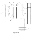
- the frontal section is provided for the design of the invention that operates on telemetric system and the alloy with shape memory.
- Said figure includes the upper part of the intramedullary pin with a constant diameter and the lower part of the intramedullary pin that may engage into this body.
- a non-cascaded (9) body which has a cavity where the extension shaft (2) can move, has one end connected with the bone by means of the fixation pins (6) and has a hollow form, the extension shaft (2) is provided to move in a downward direction without the need for an external pressure load.
- the downward movement of the extension shaft (2) is provided without the need for an externally exerted pressure load, owing to preferably two alloys (11) with shape memory, which are made of a material expanding under high temperature and reassuming its normal state under low temperature.
- the pushing force of the alloy (11) with shape memory is utilized under the effect of the expansion, owing to a movement body (10), which has a form to accommodate the extension shaft (2) and pushing apparatus, and to house and compress the extension stopper body (3), extension shaft (2), extension spring (5) and control spring (4) and has its end where the springs (4, 5) will be compressed in closed form and its other end providing the upwards and downwards movement of the extension shaft in open form.
- the extension shaft (2) is enabled to move in a downward direction within certain limits, owing to a plurality of movement body pin steps (10.1), which push the movement pins (2.1) of the movement body (10) inwards by using the capability of its hollow end (2.2) to stretch, are formed on the inner sides of said movement body (10) and are placed in the form of projections at reciprocal positions with certain intervals.
- the extension stopper body (3) is enabled to push the extension shaft (2) by compressing the extension springs (4) by virtue of the pressure load imparted on the movement body (10) pushing the pin steps (10.1) and the movement pins (2.1) of the movement body, owing to preferably two stimulus control springs (15), which are placed on the upper part of the extension stopper body (3), are compressed between the extension stopper body (3) and the movement body (10) and have the capability of force damping and pressure imparting.
- the body fluid is prevented from leaking through the gap remaining between the non-cascaded body (9) and the extension shaft (2), owing to a protective membrane (7), which is connected to the end where the non-cascaded body (9) and the extension shaft (2) join, is resistant to corrosion and capable of isolation.
- the alloys (11) with shape memory are provided to expand when necessary, owing to the resistance material (12) coated or wrapped onto the alloys (11) with shape memory.
- the heating energy is provided to the resistance material (12), owing to at least one power supply (14) connected to the resistance material (12).
- the power supply (14) is enabled to turn on and off the energy input to resistance material (12), owing to at least one telemetric sensor (13), which is connected to the power supply (14) and gives movement command by remote control or depending on certain conditions.
- the stimulus coming to the telemetric sensor (13) are transmitted to the power supply (14).
- the energy generated by the power supply (14) enables the resistances (12) wrapped around the alloys (11) with the shape memory to be heated.
- the controlled extension is provided for the alloys (11) with shape memory.
- the movement that forms as a result of the extension of the alloys (11) with shape memory reaches the movement unit (10) through the stimulus control springs (5).
- the movement pin steps (10.1) located on the inner wall of the movement unit push the unidirectional movement pins (2.1) located on the distraction (extension) shaft (2) towards the inside.
- extension shaft (2) moves in a downward direction owing to the distraction (extension) springs (4).
- This movement is gradually controlled by means of the unidirectional movement pin safety stoppers (3.1) located on the distraction (extension) amount control unit (3) and the desired amount of extension is provided.
- the fixation pins (6) passing through the bone and the intramedullary pin are used for the fixation of the lower and the upper portions. Owing to said intramedullary fixation pins without any external intervention, the existing problems related with the bone extension in the field of orthopedic oncology and orthopedic surgery will be eliminated to a considerable extent.
Landscapes
- Health & Medical Sciences (AREA)
- Orthopedic Medicine & Surgery (AREA)
- Surgery (AREA)
- Life Sciences & Earth Sciences (AREA)
- Heart & Thoracic Surgery (AREA)
- Nuclear Medicine, Radiotherapy & Molecular Imaging (AREA)
- Engineering & Computer Science (AREA)
- Biomedical Technology (AREA)
- Neurology (AREA)
- Medical Informatics (AREA)
- Molecular Biology (AREA)
- Animal Behavior & Ethology (AREA)
- General Health & Medical Sciences (AREA)
- Public Health (AREA)
- Veterinary Medicine (AREA)
- Surgical Instruments (AREA)
Applications Claiming Priority (1)
| Application Number | Priority Date | Filing Date | Title |
|---|---|---|---|
| TR2005/03768A TR200503768A2 (tr) | 2005-09-20 | 2005-09-20 | Kemik intramedüller tespit çivisi |
Publications (3)
| Publication Number | Publication Date |
|---|---|
| EP1764050A2 true EP1764050A2 (de) | 2007-03-21 |
| EP1764050A3 EP1764050A3 (de) | 2007-07-04 |
| EP1764050B1 EP1764050B1 (de) | 2010-05-26 |
Family
ID=37605718
Family Applications (1)
| Application Number | Title | Priority Date | Filing Date |
|---|---|---|---|
| EP06120844A Not-in-force EP1764050B1 (de) | 2005-09-20 | 2006-09-18 | Intramedullärer Marknagel zur Fixierung |
Country Status (4)
| Country | Link |
|---|---|
| EP (1) | EP1764050B1 (de) |
| AT (1) | ATE468822T1 (de) |
| DE (1) | DE602006014482D1 (de) |
| TR (1) | TR200503768A2 (de) |
Cited By (2)
| Publication number | Priority date | Publication date | Assignee | Title |
|---|---|---|---|---|
| US9408644B2 (en) | 2010-03-19 | 2016-08-09 | Smith & Nephew, Inc. | Telescoping IM nail and actuating mechanism |
| US9918742B2 (en) | 2011-05-16 | 2018-03-20 | Smith & Nephew, Inc. | Measuring skeletal distraction |
Family Cites Families (8)
| Publication number | Priority date | Publication date | Assignee | Title |
|---|---|---|---|---|
| US5415660A (en) * | 1994-01-07 | 1995-05-16 | Regents Of The University Of Minnesota | Implantable limb lengthening nail driven by a shape memory alloy |
| FR2726460B1 (fr) * | 1994-11-04 | 1997-04-30 | Medinov Sa | Dispositif pour l'allongement d'os longs tels que le femur |
| US5626581A (en) * | 1995-11-27 | 1997-05-06 | Volunteers For Medical Engineering | Implantable bone lengthening apparatus |
| DE19615103C2 (de) * | 1996-04-17 | 1999-04-22 | Fraunhofer Ges Forschung | Knochenmarknagel |
| DE19717357A1 (de) * | 1997-04-24 | 1999-02-11 | Augustin Prof Dr Betz | Distraktionsvorrichtung |
| DE19810639A1 (de) * | 1997-11-27 | 1999-06-02 | Fachhochschule Konstanz Hochsc | Antriebsvorrichtung mit einem aus einer Formgedächtnislegierung geformten Element sowie deren Verwendung |
| DE19829523A1 (de) * | 1998-07-02 | 2000-01-05 | Michael Butsch | Distraktionsvorrichtung zum Auseinanderbewegen eines ein- oder zweiteiligen, ggf. getrennten Knochens |
| DE10156316A1 (de) * | 2001-11-19 | 2003-06-05 | Wittenstein Ag | Distraktionsvorrichtung |
-
2005
- 2005-09-20 TR TR2005/03768A patent/TR200503768A2/xx unknown
-
2006
- 2006-09-18 AT AT06120844T patent/ATE468822T1/de not_active IP Right Cessation
- 2006-09-18 DE DE602006014482T patent/DE602006014482D1/de active Active
- 2006-09-18 EP EP06120844A patent/EP1764050B1/de not_active Not-in-force
Non-Patent Citations (1)
| Title |
|---|
| None |
Cited By (2)
| Publication number | Priority date | Publication date | Assignee | Title |
|---|---|---|---|---|
| US9408644B2 (en) | 2010-03-19 | 2016-08-09 | Smith & Nephew, Inc. | Telescoping IM nail and actuating mechanism |
| US9918742B2 (en) | 2011-05-16 | 2018-03-20 | Smith & Nephew, Inc. | Measuring skeletal distraction |
Also Published As
| Publication number | Publication date |
|---|---|
| ATE468822T1 (de) | 2010-06-15 |
| EP1764050B1 (de) | 2010-05-26 |
| DE602006014482D1 (de) | 2010-07-08 |
| EP1764050A3 (de) | 2007-07-04 |
| TR200503768A2 (tr) | 2007-04-24 |
Similar Documents
| Publication | Publication Date | Title |
|---|---|---|
| JP7119057B2 (ja) | 伸延のためのシステム及び方法 | |
| Singh et al. | The results of limb lengthening by callus distraction using an extending intramedullary nail (Fitbone) in non-traumatic disorders | |
| US4570625A (en) | Apparatus for external fixation of bone fractures | |
| JP6636420B2 (ja) | 骨整形用の装置および方法 | |
| US8551106B2 (en) | Method and apparatus for installation of intramedullary medical device | |
| JP5619875B2 (ja) | 拡張型骨インプラント | |
| US5415660A (en) | Implantable limb lengthening nail driven by a shape memory alloy | |
| CN105559868A (zh) | 一种新型棘突间固定系统 | |
| US6908467B2 (en) | Supreme distracter | |
| CN105055003B (zh) | 一种骨盆骨折复位装置及其使用方法 | |
| CN107115143A (zh) | 一种pvp可吸收支架及其成型方法 | |
| CN108236491B (zh) | 一种骨块间轴向加压力可调的骨折外固定架 | |
| EP1764050B1 (de) | Intramedullärer Marknagel zur Fixierung | |
| CN117752396B (zh) | 一种骨盆骨折微创弹性髓内固定装置 | |
| RU2584555C1 (ru) | Способ удлинения бедренной кости поверх интрамедуллярного стержня | |
| Karakoyun et al. | Intramedullary skeletal kinetic distractor in lower extremity lengthening | |
| RU153364U1 (ru) | Интрамедуллярное устройство с блокированием для остеосинтеза переломов и дефектов длинных трубчатых костей | |
| Ramlee et al. | Finite element analysis of different pin diameter of external fixator in treating tibia fracture | |
| CN118512250A (zh) | 一种加强型股骨近端螺钉 | |
| WO2016089324A1 (en) | A biomedical intramedullary device | |
| US9949772B2 (en) | Internal bone lengthener device and method of use thereof | |
| WO2009062522A2 (en) | Bone lengthening plate | |
| CN115153789A (zh) | 一种骨科骨折微创固定加固装置 | |
| CN2490987Y (zh) | 骨内外联合固定器 | |
| RU2638279C1 (ru) | Способ удлинения бедренной кости поверх интрамедуллярного стержня |
Legal Events
| Date | Code | Title | Description |
|---|---|---|---|
| PUAI | Public reference made under article 153(3) epc to a published international application that has entered the european phase |
Free format text: ORIGINAL CODE: 0009012 |
|
| AK | Designated contracting states |
Kind code of ref document: A2 Designated state(s): AT BE BG CH CY CZ DE DK EE ES FI FR GB GR HU IE IS IT LI LT LU LV MC NL PL PT RO SE SI SK TR |
|
| AX | Request for extension of the european patent |
Extension state: AL BA HR MK YU |
|
| PUAL | Search report despatched |
Free format text: ORIGINAL CODE: 0009013 |
|
| AK | Designated contracting states |
Kind code of ref document: A3 Designated state(s): AT BE BG CH CY CZ DE DK EE ES FI FR GB GR HU IE IS IT LI LT LU LV MC NL PL PT RO SE SI SK TR |
|
| AX | Request for extension of the european patent |
Extension state: AL BA HR MK YU |
|
| 17P | Request for examination filed |
Effective date: 20080103 |
|
| AKX | Designation fees paid | ||
| 17Q | First examination report despatched |
Effective date: 20080326 |
|
| RBV | Designated contracting states (corrected) |
Designated state(s): AT BE BG CH CY CZ DE DK EE ES FI FR GB GR HU IE IS IT LI LT LU LV MC NL PL PT RO SE SI SK TR |
|
| REG | Reference to a national code |
Ref country code: DE Ref legal event code: 8566 |
|
| RBV | Designated contracting states (corrected) |
Designated state(s): AT BE BG CH CY CZ DE DK EE ES FI FR GB GR HU IE IS IT LI LT LU LV MC NL PL PT RO SE SI SK TR |
|
| GRAP | Despatch of communication of intention to grant a patent |
Free format text: ORIGINAL CODE: EPIDOSNIGR1 |
|
| RIN1 | Information on inventor provided before grant (corrected) |
Inventor name: OFLAZ, HAKAN Inventor name: UZUN, BORA Inventor name: BARAN, ONDER Inventor name: HAVITCIOGLU, HASAN |
|
| GRAS | Grant fee paid |
Free format text: ORIGINAL CODE: EPIDOSNIGR3 |
|
| GRAA | (expected) grant |
Free format text: ORIGINAL CODE: 0009210 |
|
| AK | Designated contracting states |
Kind code of ref document: B1 Designated state(s): AT BE BG CH CY CZ DE DK EE ES FI FR GB GR HU IE IS IT LI LT LU LV MC NL PL PT RO SE SI SK TR |
|
| REG | Reference to a national code |
Ref country code: GB Ref legal event code: FG4D |
|
| REG | Reference to a national code |
Ref country code: CH Ref legal event code: EP |
|
| REG | Reference to a national code |
Ref country code: IE Ref legal event code: FG4D |
|
| REF | Corresponds to: |
Ref document number: 602006014482 Country of ref document: DE Date of ref document: 20100708 Kind code of ref document: P |
|
| REG | Reference to a national code |
Ref country code: NL Ref legal event code: VDEP Effective date: 20100526 |
|
| LTIE | Lt: invalidation of european patent or patent extension |
Effective date: 20100526 |
|
| PG25 | Lapsed in a contracting state [announced via postgrant information from national office to epo] |
Ref country code: LT Free format text: LAPSE BECAUSE OF FAILURE TO SUBMIT A TRANSLATION OF THE DESCRIPTION OR TO PAY THE FEE WITHIN THE PRESCRIBED TIME-LIMIT Effective date: 20100526 Ref country code: SE Free format text: LAPSE BECAUSE OF FAILURE TO SUBMIT A TRANSLATION OF THE DESCRIPTION OR TO PAY THE FEE WITHIN THE PRESCRIBED TIME-LIMIT Effective date: 20100526 |
|
| PG25 | Lapsed in a contracting state [announced via postgrant information from national office to epo] |
Ref country code: SI Free format text: LAPSE BECAUSE OF FAILURE TO SUBMIT A TRANSLATION OF THE DESCRIPTION OR TO PAY THE FEE WITHIN THE PRESCRIBED TIME-LIMIT Effective date: 20100526 Ref country code: IS Free format text: LAPSE BECAUSE OF FAILURE TO SUBMIT A TRANSLATION OF THE DESCRIPTION OR TO PAY THE FEE WITHIN THE PRESCRIBED TIME-LIMIT Effective date: 20100926 Ref country code: FI Free format text: LAPSE BECAUSE OF FAILURE TO SUBMIT A TRANSLATION OF THE DESCRIPTION OR TO PAY THE FEE WITHIN THE PRESCRIBED TIME-LIMIT Effective date: 20100526 Ref country code: AT Free format text: LAPSE BECAUSE OF FAILURE TO SUBMIT A TRANSLATION OF THE DESCRIPTION OR TO PAY THE FEE WITHIN THE PRESCRIBED TIME-LIMIT Effective date: 20100526 Ref country code: LV Free format text: LAPSE BECAUSE OF FAILURE TO SUBMIT A TRANSLATION OF THE DESCRIPTION OR TO PAY THE FEE WITHIN THE PRESCRIBED TIME-LIMIT Effective date: 20100526 |
|
| PG25 | Lapsed in a contracting state [announced via postgrant information from national office to epo] |
Ref country code: PL Free format text: LAPSE BECAUSE OF FAILURE TO SUBMIT A TRANSLATION OF THE DESCRIPTION OR TO PAY THE FEE WITHIN THE PRESCRIBED TIME-LIMIT Effective date: 20100526 Ref country code: GR Free format text: LAPSE BECAUSE OF FAILURE TO SUBMIT A TRANSLATION OF THE DESCRIPTION OR TO PAY THE FEE WITHIN THE PRESCRIBED TIME-LIMIT Effective date: 20100827 Ref country code: CY Free format text: LAPSE BECAUSE OF FAILURE TO SUBMIT A TRANSLATION OF THE DESCRIPTION OR TO PAY THE FEE WITHIN THE PRESCRIBED TIME-LIMIT Effective date: 20100526 |
|
| PG25 | Lapsed in a contracting state [announced via postgrant information from national office to epo] |
Ref country code: EE Free format text: LAPSE BECAUSE OF FAILURE TO SUBMIT A TRANSLATION OF THE DESCRIPTION OR TO PAY THE FEE WITHIN THE PRESCRIBED TIME-LIMIT Effective date: 20100526 Ref country code: PT Free format text: LAPSE BECAUSE OF FAILURE TO SUBMIT A TRANSLATION OF THE DESCRIPTION OR TO PAY THE FEE WITHIN THE PRESCRIBED TIME-LIMIT Effective date: 20100927 Ref country code: NL Free format text: LAPSE BECAUSE OF FAILURE TO SUBMIT A TRANSLATION OF THE DESCRIPTION OR TO PAY THE FEE WITHIN THE PRESCRIBED TIME-LIMIT Effective date: 20100526 Ref country code: DK Free format text: LAPSE BECAUSE OF FAILURE TO SUBMIT A TRANSLATION OF THE DESCRIPTION OR TO PAY THE FEE WITHIN THE PRESCRIBED TIME-LIMIT Effective date: 20100526 |
|
| PG25 | Lapsed in a contracting state [announced via postgrant information from national office to epo] |
Ref country code: BE Free format text: LAPSE BECAUSE OF FAILURE TO SUBMIT A TRANSLATION OF THE DESCRIPTION OR TO PAY THE FEE WITHIN THE PRESCRIBED TIME-LIMIT Effective date: 20100526 Ref country code: SK Free format text: LAPSE BECAUSE OF FAILURE TO SUBMIT A TRANSLATION OF THE DESCRIPTION OR TO PAY THE FEE WITHIN THE PRESCRIBED TIME-LIMIT Effective date: 20100526 Ref country code: RO Free format text: LAPSE BECAUSE OF FAILURE TO SUBMIT A TRANSLATION OF THE DESCRIPTION OR TO PAY THE FEE WITHIN THE PRESCRIBED TIME-LIMIT Effective date: 20100526 Ref country code: CZ Free format text: LAPSE BECAUSE OF FAILURE TO SUBMIT A TRANSLATION OF THE DESCRIPTION OR TO PAY THE FEE WITHIN THE PRESCRIBED TIME-LIMIT Effective date: 20100526 |
|
| PG25 | Lapsed in a contracting state [announced via postgrant information from national office to epo] |
Ref country code: IT Free format text: LAPSE BECAUSE OF FAILURE TO SUBMIT A TRANSLATION OF THE DESCRIPTION OR TO PAY THE FEE WITHIN THE PRESCRIBED TIME-LIMIT Effective date: 20100526 |
|
| PLBE | No opposition filed within time limit |
Free format text: ORIGINAL CODE: 0009261 |
|
| STAA | Information on the status of an ep patent application or granted ep patent |
Free format text: STATUS: NO OPPOSITION FILED WITHIN TIME LIMIT |
|
| PG25 | Lapsed in a contracting state [announced via postgrant information from national office to epo] |
Ref country code: MC Free format text: LAPSE BECAUSE OF NON-PAYMENT OF DUE FEES Effective date: 20100930 |
|
| REG | Reference to a national code |
Ref country code: CH Ref legal event code: PL |
|
| 26N | No opposition filed |
Effective date: 20110301 |
|
| GBPC | Gb: european patent ceased through non-payment of renewal fee |
Effective date: 20100918 |
|
| REG | Reference to a national code |
Ref country code: DE Ref legal event code: R097 Ref document number: 602006014482 Country of ref document: DE Effective date: 20110228 |
|
| REG | Reference to a national code |
Ref country code: FR Ref legal event code: ST Effective date: 20110531 |
|
| REG | Reference to a national code |
Ref country code: DE Ref legal event code: R119 Ref document number: 602006014482 Country of ref document: DE Effective date: 20110401 |
|
| PG25 | Lapsed in a contracting state [announced via postgrant information from national office to epo] |
Ref country code: CH Free format text: LAPSE BECAUSE OF NON-PAYMENT OF DUE FEES Effective date: 20100930 Ref country code: DE Free format text: LAPSE BECAUSE OF NON-PAYMENT OF DUE FEES Effective date: 20110401 Ref country code: IE Free format text: LAPSE BECAUSE OF NON-PAYMENT OF DUE FEES Effective date: 20100918 Ref country code: FR Free format text: LAPSE BECAUSE OF NON-PAYMENT OF DUE FEES Effective date: 20100930 Ref country code: LI Free format text: LAPSE BECAUSE OF NON-PAYMENT OF DUE FEES Effective date: 20100930 |
|
| PG25 | Lapsed in a contracting state [announced via postgrant information from national office to epo] |
Ref country code: GB Free format text: LAPSE BECAUSE OF NON-PAYMENT OF DUE FEES Effective date: 20100918 |
|
| PG25 | Lapsed in a contracting state [announced via postgrant information from national office to epo] |
Ref country code: BG Free format text: LAPSE BECAUSE OF FAILURE TO SUBMIT A TRANSLATION OF THE DESCRIPTION OR TO PAY THE FEE WITHIN THE PRESCRIBED TIME-LIMIT Effective date: 20100526 Ref country code: HU Free format text: LAPSE BECAUSE OF FAILURE TO SUBMIT A TRANSLATION OF THE DESCRIPTION OR TO PAY THE FEE WITHIN THE PRESCRIBED TIME-LIMIT Effective date: 20101127 Ref country code: LU Free format text: LAPSE BECAUSE OF NON-PAYMENT OF DUE FEES Effective date: 20100918 |
|
| PG25 | Lapsed in a contracting state [announced via postgrant information from national office to epo] |
Ref country code: BG Free format text: LAPSE BECAUSE OF FAILURE TO SUBMIT A TRANSLATION OF THE DESCRIPTION OR TO PAY THE FEE WITHIN THE PRESCRIBED TIME-LIMIT Effective date: 20100826 |
|
| PG25 | Lapsed in a contracting state [announced via postgrant information from national office to epo] |
Ref country code: ES Free format text: LAPSE BECAUSE OF FAILURE TO SUBMIT A TRANSLATION OF THE DESCRIPTION OR TO PAY THE FEE WITHIN THE PRESCRIBED TIME-LIMIT Effective date: 20100906 |
|
| PGFP | Annual fee paid to national office [announced via postgrant information from national office to epo] |
Ref country code: TR Payment date: 20170918 Year of fee payment: 12 |
|
| PG25 | Lapsed in a contracting state [announced via postgrant information from national office to epo] |
Ref country code: TR Free format text: LAPSE BECAUSE OF NON-PAYMENT OF DUE FEES Effective date: 20180918 |