EP1764179A2 - Kontaktspitze mit einem Flansch Isolierende Schutzhülse; Metallische Düse mit Greifmitteln; Brenner zum Lichtbogenschweissen mit einem Draht und entprechender Kontaktspitze, isolierender Schutzhülse und metallischer Düse - Google Patents
Kontaktspitze mit einem Flansch Isolierende Schutzhülse; Metallische Düse mit Greifmitteln; Brenner zum Lichtbogenschweissen mit einem Draht und entprechender Kontaktspitze, isolierender Schutzhülse und metallischer Düse Download PDFInfo
- Publication number
- EP1764179A2 EP1764179A2 EP06005578A EP06005578A EP1764179A2 EP 1764179 A2 EP1764179 A2 EP 1764179A2 EP 06005578 A EP06005578 A EP 06005578A EP 06005578 A EP06005578 A EP 06005578A EP 1764179 A2 EP1764179 A2 EP 1764179A2
- Authority
- EP
- European Patent Office
- Prior art keywords
- torch
- cylindrical
- nozzle
- diffuser
- protective sleeve
- Prior art date
- Legal status (The legal status is an assumption and is not a legal conclusion. Google has not performed a legal analysis and makes no representation as to the accuracy of the status listed.)
- Granted
Links
Images


Classifications
-
- B—PERFORMING OPERATIONS; TRANSPORTING
- B23—MACHINE TOOLS; METAL-WORKING NOT OTHERWISE PROVIDED FOR
- B23K—SOLDERING OR UNSOLDERING; WELDING; CLADDING OR PLATING BY SOLDERING OR WELDING; CUTTING BY APPLYING HEAT LOCALLY, e.g. FLAME CUTTING; WORKING BY LASER BEAM
- B23K9/00—Arc welding or cutting
- B23K9/24—Features related to electrodes
- B23K9/28—Supporting devices for electrodes
- B23K9/29—Supporting devices adapted for making use of shielding means
- B23K9/291—Supporting devices adapted for making use of shielding means the shielding means being a gas
- B23K9/295—Supporting devices adapted for making use of shielding means the shielding means being a gas using consumable wire electrodes
-
- B—PERFORMING OPERATIONS; TRANSPORTING
- B23—MACHINE TOOLS; METAL-WORKING NOT OTHERWISE PROVIDED FOR
- B23K—SOLDERING OR UNSOLDERING; WELDING; CLADDING OR PLATING BY SOLDERING OR WELDING; CUTTING BY APPLYING HEAT LOCALLY, e.g. FLAME CUTTING; WORKING BY LASER BEAM
- B23K9/00—Arc welding or cutting
- B23K9/12—Automatic feeding or moving of electrodes or work for spot or seam welding or cutting
- B23K9/122—Devices for guiding electrodes, e.g. guide tubes
- B23K9/123—Serving also as contacting devices supplying welding current to an electrode
-
- B—PERFORMING OPERATIONS; TRANSPORTING
- B23—MACHINE TOOLS; METAL-WORKING NOT OTHERWISE PROVIDED FOR
- B23K—SOLDERING OR UNSOLDERING; WELDING; CLADDING OR PLATING BY SOLDERING OR WELDING; CUTTING BY APPLYING HEAT LOCALLY, e.g. FLAME CUTTING; WORKING BY LASER BEAM
- B23K9/00—Arc welding or cutting
- B23K9/16—Arc welding or cutting making use of shielding gas
- B23K9/173—Arc welding or cutting making use of shielding gas and of a consumable electrode
-
- B—PERFORMING OPERATIONS; TRANSPORTING
- B23—MACHINE TOOLS; METAL-WORKING NOT OTHERWISE PROVIDED FOR
- B23K—SOLDERING OR UNSOLDERING; WELDING; CLADDING OR PLATING BY SOLDERING OR WELDING; CUTTING BY APPLYING HEAT LOCALLY, e.g. FLAME CUTTING; WORKING BY LASER BEAM
- B23K9/00—Arc welding or cutting
- B23K9/24—Features related to electrodes
- B23K9/28—Supporting devices for electrodes
- B23K9/282—Electrode holders not supplying shielding means to the electrode
-
- B—PERFORMING OPERATIONS; TRANSPORTING
- B23—MACHINE TOOLS; METAL-WORKING NOT OTHERWISE PROVIDED FOR
- B23K—SOLDERING OR UNSOLDERING; WELDING; CLADDING OR PLATING BY SOLDERING OR WELDING; CUTTING BY APPLYING HEAT LOCALLY, e.g. FLAME CUTTING; WORKING BY LASER BEAM
- B23K9/00—Arc welding or cutting
- B23K9/24—Features related to electrodes
- B23K9/28—Supporting devices for electrodes
- B23K9/285—Cooled electrode holders
Definitions
- the invention relates to the art of electric arc welding and more particularly to an improved torch for the gun between a wire feeder and the welding operation.
- a "gun” In electric arc welding, a "gun" is a flexible, elongated element having a rear end connected to a wire feeder and power source and a front end for a welding torch.
- the gun includes an elongated flexible conduit directing current and shielding gas from the wire feeder to the welding torch.
- a welding gun is employed for hand held welding and for robotic controlled welding.
- Many torches are designed to be water cooled; therefore, the flexible tubing from the wire feeder at the rear end to the torch includes a coolant inlet and a coolant outlet to direct liquid coolant, such as water, into the torch around the torch and then back to a reservoir.
- the torch must, whether water cooled or not, include a contact tip through which the welding wire from the wire feeder is directed to the welding operation.
- This tip is highly conductive, generally copper, and supported in a conductive cylindrical main assembly.
- This assembly establishes physical integrity of the torch and receives power from the power source, through the wire feeder.
- conduits within the main assembly direct water around the assembly to maintain a reduced temperature during the welding operation.
- Shielding gas is directed from a diffuser forming an integral part of the main assembly into an annular chamber defined by an outer replaceable nozzle. Shielding gas from the nozzle flows around the contact tip so the shielding gas forms a protective barrier between the molten metal of the welding operation and the ambient atmosphere. All of these requirements of a welding torch require complex machined components which substantially increases the cost of the torch and adversely affects the operability of the torch during the welding operation.
- the welding operation itself creates spatter, especially during short circuit conditions, so the forward end of the torch is subject to substantial deterioration over time caused by spatter together with the tremendous arc temperature involved in the welding operation. All of these adverse conditions create restraints in the design of a torch. They are taken into consideration and substantially improved by the present invention, which involves several novel features for the torch portion of the welding gun.
- a major objective is improving the torch sot it remains cool, especially for a water cooled torch.
- the design of the cooling jacket on the torch in existing torches has often proved unsatisfactory. It is recognized that the water jacket or chambers of the water cooled torch should be as close as possible to the arc, since the excessive heat comes from the arc itself.
- the water cooling passageways in the torch itself must be designed for efficient cooling of the torch and without affecting the cost and/or the physical strength of the torch. This feature is improved by the novel torch of the invention.
- Another problem to be solved by the present invention arises from the overheating of the torch end causing rapid deterioration of the electrical insulation in the torch.
- This insulation material rapidly deteriorates if overheated. Consequently, in the water cooled torch the cooling jacket or passages should be as close as possible to the arc to prevent excessive heating being transmitted to the insulation of the torch.
- shielding gas is directed into the welding operation from diffuser orifices circumferentially spaced around the torch. This gas has a cooling function as it moves around the main assembly to the contact tip at the welding operation. Consequently, torches require diffuser orifices for shielding gas; however, these orifices must be oriented to prevent unwanted cavitation and turbulence.
- the present invention is directed to a torch for solving all of these problems to provide an improved torch for an arc welding gun.
- the present invention relates to an improved welding torch that protects the end of the torch from heat deterioration and damage by excessive spatter, while still maintaining essentially laminar flow of shielding gas to the welding operation.
- an improved torch for directing a welding wire with a given diameter toward a workpiece.
- the torch comprises a cylindrical conductive main assembly having a diffuser with a plurality of circumferentially spaced shielding gas diffuser orifices for directing shielding gas radially outwardly from the assembly.
- a forwardly facing threaded bore extending through a cylindrical support nose mounted on the end of the main assembly and an elongated wire passageway coextensive with the threaded bore and opening at the rear end of the main assembly.
- the passageway is isolated fluid wise from the diffuser orifices.
- the novel torch also includes an insulated, cylindrical protective sleeve fitted around both the support nose at the end of the main assembly and the diffuser orifices of the main assembly.
- This protective sleeve has a front clearance opening and circumferentially spaced openings generally aligned with the diffuser orifices or a chamber receiving shielding gas from the orifices.
- a further component of the improved torch is a contact tip having a central wire guide bore with a diameter only slightly larger than the diameter of the welding wire, a threaded rear body, a front extension passing through the front clearance opening of the sleeve and a radially extending flange between the rear body and the front extension to hold the protective sleeve around the nose fixed on the main assembly when the body is screwed into the threaded bore of the main assembly of the torch.
- the flange is rotatably mounted on the contact tip. Otherwise it is machined integrally with the tip, such as by a screw machine.
- the main assembly When the torch is a water cooled torch, the main assembly includes an inward most coolant passage with an inlet conduit and an outlet conduit provided in the main assembly.
- the coolant passage is annular and generally coaxial with the threaded bore of the main assembly.
- the annular coolant passage has a frontmost portion and the threaded rear body of the contact tip has a rearmost portion, with the portions overlapping. This provides direct heat conductivity from the tip to the coolant passage.
- an insulated sleeve surrounds the main assembly and a cylindrical metal nozzle is provided to define the external handling structure for the torch.
- the metal nozzle has a rear end held over the insulated sleeve of the cylindrical assembly and a front end flared inwardly forward of the tip so the nozzle is spaced from the protective sleeve to define an annular shielding gas passage from the openings of the sleeve to the front end of the nozzle.
- the rear end of the cylindrical metal nozzle includes a gripping mechanism.
- One aspect of the present invention is to provide a novel gripping mechanism.
- This novel gripping mechanism includes a first generally cylindrical collet at the rear end of the nozzle and having at least one axially extending collapsible slot and an outwardly facing cylindrical surface.
- a second generally cylindrical actuator ring with an inner generally cylindrical surface slides around the outer facing surface of the collet.
- At least one of the relatively rotatable surfaces is slightly non-circular so rotation of the actuator ring on the collet closes the nozzle slot and clamps the rear end of the nozzle onto the main cylindrical assembly of the torch.
- Another embodiment of the gripping mechanism does not involve a separate actuator ring, but includes a first cylindrical surface fixed with respect to the main cylindrical assembly of the torch. The first surface has a groove with a snap ring protruding from the first surface.
- the rear end of the nozzle includes an inner surface generally matching the first surface and has an annular groove to receive and hold the snap ring when the inner surface of the nozzle is slipped axially over the first surface fixed on the main assembly.
- the nozzle is merely moved axially onto the main assembly of the nozzle to a position where the groove internal of the nozzle receives and holds the snap ring.
- Another embodiment of the gripping mechanism is merely a fixed friction surface on the cylindrical surface of the main assembly.
- the rear of the nozzle includes an inner friction surface generally matching the first friction surface to hold the nozzle onto the first friction surface by frictional force.
- the diffuser having circumferentially spaced diffuser orifices and the forward nose are integral with the main assembly.
- the integral relationship is formed by threading the nose into the diffuser.
- the integral relationship is by machining the nose as part of the diffuser.
- a contact tip for use in a torch for directing welding wire with a given diameter toward a workpiece.
- the contact tip has a central wire guide bore with a diameter only slightly larger than the diameter of the welding wire, a threaded rear body, a front extension and a radially extending flange between the rear body and the front extension.
- the flange is rotatably mounted on the contact tip.
- the outer edge of the flange can be circular or non-circular without departing from the intended scope of the invention.
- Yet another aspect of the invention is the provision of an insulated cylindrical protective sleeve for mounting around the nose and circumferentially spaced diffuser orifices of a torch.
- the sleeve has a front clearance opening and circumferentially spaced openings communicated with the diffuser openings when the sleeve is mounted.
- the protective sleeve has a first inner portion having a cylindrical cavity to match the outside periphery of the nose and a second portion having a cylindrical cavity matching the outer periphery of the diffuser providing the diffuser openings.
- the protective sleeve is formed from a thermoplastic material that is not substantially eroded by spatter. In practice, the sleeve is formed from tetrafluoroethylene.
- the primary object of the present invention is to provide an improved welding torch for mounting on the front end of a welding gun, which torch has structure to protect the front end of the gun from heat deterioration and spatter erosion.
- Yet another object of the invention is the provision of a welding torch, as defined above, which welding torch has a protective sleeve to insulate the end of the torch from heat and protect the diffuser orifices from abrasion by spatter.
- Another object of the present invention is the provision of a contact tip for a welding torch, which contact tip has an intermediate flange used to hold a surrounding insulated protective sleeve onto the end of the main cylindrical assembly of the torch.
- Still a further object of the present invention is the provision of a protective sleeve surrounding the end of the main cylindrical assembly of the torch and also the diffuser orifices of the torch to reduce exposure to high temperatures and prevent spatter abrasion.
- Still another object of the present invention is the provision of a novel outer nozzle for a welding torch, which nozzle has a rear gripping mechanism comprising a rotatable actuator ring having an eccentric inner surface rotatable to clamp the rear end of the nozzle onto the outer surface of the torch.
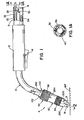
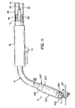
- torch A the preferred embodiment of the present invention is illustrated as torch A, goose neck 10 extending from handle 12.
- An optional manually operated trigger 14 is illustrated for handle 12; however, in most embodiments, torch A is used in a robotic environment having no external trigger 14.
- the torch is at the front end of welding gun G, which gun is an elongated device extending from a wire feeder to the welding operation where wire W is melted and transferred to workpiece WP.
- the rear end of gun G not shown, forms no part of the present invention except to realize that the gun includes a flexible tube 40 extending from rear wire feeder to handle 12 supporting torch A. Wire W of a given diameter is directed from the wire feeder to torch A through liner 22.
- Flexible, long tube 20 houses an inlet coolant conduit 32 and an outlet conduit 34 for directing coolant, such as water, into and away from torch A when the torch is a water cooled type torch as in the preferred embodiment of the invention.
- coolant conduit includes a central passage 36 surrounded by a braided or woven power lead 40.
- two power leads are directed through goose neck 10 to the torch for the purpose of directing welding current of the desired magnitude and waveform into the torch.
- metal nozzle 50 is mounted over the end of torch A.
- nozzle A has a gripping device involving an actuator ring 52 rotated about the rear end of nozzle 50 by knurled sections 54, 56.
- Tube 20 houses wire W passing through liner 22 as well as defining the surrounding annulus shielding gas passage 30 so coolant moves in through conduit 32 and is withdrawn through conduit 34 as shown in FIGURE 1.
- two power leads 40 around passages 36 are used for directing welding current to torch A.
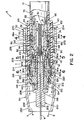
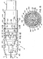
- torch A has an inner cylindrical main assembly 60. This is the main torch defining assembly and is used to conduct current from power leads 40 to wire W for the welding operation.
- Cylindrical main assembly includes several machined metal components all of which are supported onto a central support tube 62 having diametrically opposed flats 64, 66 wherein the inlet water passage is formed by flat 64 and the outlet water passage is formed by flat 66.
- the arrows a represent the inlet water movement and arrows b indicate the outlet water.
- Tube 70 is mounted on support tube 62 to close the water conduits formed by flats 64, 66 and provide diametrically opposed openings 72, 74.
- diffuser 80 As an integral part of conductive assembly 60.
- the rear section of the unitary diffuser includes opening 80a communicated with shielding gas passage 30.
- Shoulders 82, 84 locate cylindrical extension 86 around tube 70 with holes 86a, 86b aligning with outlet opening 72, 74 of fixed concentric tube 70.
- coolant flows on the outside of tube 62 through opening 72 and holes 86a into annular channel or chamber 90 closed by an outer concentric sleeve portion 92 abutted against the forward end of extension 86 to define outer coolant cylindrical chamber 90 having an outermost end 90a.
- Annular channel 90 is closed by concentric sleeve 92 abutting the back end of diffuser portion 80 of main assembly 60.
- diffuser 80 is integral with assembly 60 by being a machine inner part of the assembly. This component performs the function of directing cooling liquid to the torch; however, the primary function of diffuser 80 is to provide shielding gas at the welding operation.
- diffuser 80 has an annular manifold 110 with axially defined ports 112 intersecting a lower surface 114. Axially machined orifices 120 intersect axial ports 112 to provide the orifices for diffuser 80 to direct shielding gas into a cylindrical chamber 122.
- the innermost portion of diffuser 80 is a threaded passage 130 to receive support nose 150. That defines a forward facing bore 140 of assembly 60.
- Bore 140 includes a rear end 142 having an opening 144 for wire W and a rearwardly facing nest or recess 146 for supporting the terminal end of liner 22.
- Support nose 150 is mounted in threaded passage 130 of the front part of the diffuser and includes forwardly facing, stepped cylindrical sections 152, 154 with clearance bore 156 for the wire.
- Rear surface 158 engages surface 114 of the diffuser to close axially extending ports 112 forcing shielding gas radially through diffuser orifices 120.
- Nose 150 has a rear threaded body 160 received in threaded passage 130 of diffuser 80. This body terminates in the rear opening 144 and nest recess 146 as previously described.
- Assembly 60 includes integral diffuser 80 and concentric tubes held together by nose 150.
- Assembly 60 is clamped together by threading nose 150 into openings 130 so it is a complete unit having forwardly facing threaded bore 140. That bore receives the contact tip 200 for guiding wire W to the welding operation and communicating electrical power to the advancing wire.
- contact tip 200 is novel and includes a central wire guide passage 202 having a diameter slightly larger than the diameter of wire W.
- Rear threaded body 204 is threaded into bore 140 of assembly 60 and supports an outwardly protruding extension 206 defining the stick out of wire W during the welding operation.
- Radially extending flange 208 is mounted on tip 200 between threaded body 204 and extension 206. This radially extending flange is machined as part of the tip or it can be rotatably mounted on the tip as shown in FIGURE 15.
- Innermost end 209 of body 204 is further inward than end 90a of annular channel 90. Thus, there is an overlap illustrated as c between the outermost position of the cooling water and the innermost position of tip 200.
- Flange 208 holds protective sleeve 210 against shoulder 148 of support nose 150.
- This protective sleeve is formed from a thermoplastic heat resistant material, such as tetrafluoroethylene, and is molded or machined to match nose 150 by two step cavity 148.
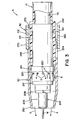
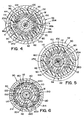
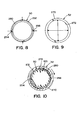
- the first step centers sleeve 210 over nose 150 and the rearward step defines cup 214 having openings 220 communicated with cylindrical chamber 122 providing shielding gas from orifices 120. Openings 220, as best shown in FIGURES 3 and 7, are essentially aligned with orifices 120 to provide shielding gas in the annular passageway formed by replaceable metal orifice 50.
- the gas flow is substantially linear.
- Nozzle 50 includes a front end 250 flared inwardly and a rear end 252 around the outer surface 102 of insulation sleeve 100.
- rear end 252 has one or more axially extending collapsible slots 244, 246 intersecting the outer surface 260 at the rear end of nozzle 50.
- Actuator ring 52 has an inner surface 270 and is slipped over and rotatable on outer surface 260 of rear end 252 of nozzle 50, as best shown in FIGURE 7.
- surfaces 260, 270 are eccentric so that rotation of ring 52 over end 252 cams slots 254, 256 together to clamp the rear end of nozzle 50 onto insulation sleeve 100.
- knurled sections 54, 56 allow an operator to apply the necessary rotary force to forcibly clamp the nozzle onto torch A.
- This is the preferred gripping mechanism for the nozzle; however, other gripping mechanisms can be used and are shown in the other embodiments of the invention.
- FIGURES 11-13 A second embodiment of a water cooled version of the present invention is illustrated in FIGURES 11-13 wherein the numbers of like components from the first embodiment are numbered the same.
- the basic difference relates to the gripping mechanism at the rear end of the nozzle.
- Torch A' has an insulation sleeve 100' with an outer cylindrical surface 102'.
- Nozzle 100 has a front end 302 with a gas directing flare and a rear end 304 with an inner cylindrical surface 306 generally matching surface 100'.
- the gripping mechanism of nozzle 300 includes a circumferentially extending groove 310 in sleeve 100'.
- the groove receives snap ring 312 which expands outwardly from surface 102'.
- Rearward of groove 310 is a second groove 320 for a circular sealing ring 322.
- end 302 of nozzle 300 has two snap ring receiving grooves 330, 332.
- snap ring 312 extends into groove 310 and seal 322 provides a gas seal at the rear of the nozzle.
- the nozzle is merely forced rearward beyond groove 310 until ring 312 snaps into groove 320. In both instances, there is a rear seal by sealing ring 322. This is a further arrangement for mounting the nozzle onto the welding torch.
- Torch 400 is attached to goose neck 402 extending from handle 404 and having an optional trigger 406, as previously described.
- Flexible tube 410 extends from a wire feeder to handle 404 for directing wire W through liner 412 and shielding gas through annular passage 414. There are no coolant passages; however, a power lead, or two power leads, are directed from the power source to the torch through annular passage 414 of tube 410.
- the illustrated embodiment includes metal connector 420 with a forwardly cylindrical projection 422 supporting an annular seal 444 between projection 422 and inner recess 426 of insulator 428.
- the insulator is clamped between connector 420 and the main cylindrical support member 440 which is drawn toward the connector by stub shaft 430 through the use of outer threads 432. Shielding gas is directed through connector 420 into main support member 440.
- This support member provides a cylindrical main assembly as in the prior water cooled torches.
- Member 440 is a machined cylindrical member having a rear end flange 442 surrounding threaded bore 444 used to draw member 440 toward connector 420 to clamp these two structures on insulator 428.
- support member 440 To support the forward end of liner 412, support member 440 includes a rearwardly facing nest portion 446 surrounding a wire opening 448.
- the main support member is machined to define a forwardly directed diffuser section having circumferentially spaced diffuser openings 450 and bled passages 452 so shielding gas g from annular passage 414 is directed through threaded bore 444 and into both the radial orifices 450 and the bled ports 452. This communicates shielding gas with annular distribution chamber 460 for use in the welding operation.
- main assembly 440 includes a front support nose 470. This unit has the nose machined as a part of the total assembly. This nose defines forwardly facing threaded bore 472 and outer surface 474.
- torch 400 includes a central cylindrical support assembly with a forwardly facing diffuser having radially directed orifices and a nose with a threaded bore facing forward.
- This bore receives contact tips 500 having a central wire guide bore 502 or passage and a threaded rear body 504.
- contact tip 500 has a forward extension 506.
- the extension and rear body are on opposite sides of a radially extending flange 508, which is illustrated as rotatable in a slot 509 of tip 500.
- support member 440 is a brass mounting sleeve 510 with an inner cylindrical surface acted upon by outwardly biased snap ring 512 and circular ring seal 514 carried on the outer surface of member 440.
- Groove 520 on the inner surface of sleeve 510 coacts with snap ring 512 to hold brass sleeve 510 in a position around member 440.
- brass sleeve 510 is releasably mounted on support member 540 to receive an outer ceramic sleeve 530 which is held by friction over the outer surface of brass sleeve 510.
- Ceramic support sleeve 530 has an outer cylindrical surface 532 which coacts with a recessed surface 542 to hold metal nozzle 540 in the position shown in FIGURE 15.
- nozzle 540 is held on torch 400 by friction force between the outer cylindrical surface 532 and the recessed inner cylindrical surface 542.
- this type of nozzle could be used in the other two embodiments.
- the nozzles in the other two embodiments could be used in the torch shown in FIGURES 14 and 15.
- Torch 400 includes a protective sleeve 550 with the same attributes and functions as protective sleeve 510 of the two water cooled embodiments.
- Sleeve 550 is held on the end of member 440 by flange 508 of tip 500.
- the flange engages front end 552 having central opening 554.
- Shoulder 556 clamps end 552 against the outermost end of member 440.
- This action mounts and holds sleeve 550 around the outer nose portion of assembly 440 while rearwardly extending cup section 560 surrounds orifices 450 and includes circumferentially spaced openings 460 communicated with the diffuser orifices by way of intermediate chamber 460.
- the protective sleeve is mounted over the outer nose of the main conductive assembly of the torch and extends rearwardly to provide openings communicating the diffuser openings so the annular passage created by the outer metal nozzle can direct an efficient gas flow to the welding operation.
- the protective sleeve has the same advantages as previously described sleeves. It protects the end of the conductive assembly that supports the contact tip and the outer diffuser openings fo shielding gas.
Landscapes
- Engineering & Computer Science (AREA)
- Physics & Mathematics (AREA)
- Plasma & Fusion (AREA)
- Mechanical Engineering (AREA)
- Arc Welding In General (AREA)
Applications Claiming Priority (1)
| Application Number | Priority Date | Filing Date | Title |
|---|---|---|---|
| US11/229,239 US8552341B2 (en) | 2005-09-19 | 2005-09-19 | Torch for arc welding gun |
Publications (3)
| Publication Number | Publication Date |
|---|---|
| EP1764179A2 true EP1764179A2 (de) | 2007-03-21 |
| EP1764179A3 EP1764179A3 (de) | 2007-05-23 |
| EP1764179B1 EP1764179B1 (de) | 2010-09-01 |
Family
ID=37497844
Family Applications (1)
| Application Number | Title | Priority Date | Filing Date |
|---|---|---|---|
| EP06005578A Expired - Lifetime EP1764179B1 (de) | 2005-09-19 | 2006-03-18 | Brenner zum Lichtbogenschweissen mit einem Draht und einer Kontaktspitze, einer isolierenden Schutzhülse und einer metallischen Düse |
Country Status (8)
| Country | Link |
|---|---|
| US (1) | US8552341B2 (de) |
| EP (1) | EP1764179B1 (de) |
| CN (3) | CN1935439B (de) |
| AT (1) | ATE479516T1 (de) |
| AU (1) | AU2006200570B2 (de) |
| CA (2) | CA2535077C (de) |
| DE (1) | DE602006016529D1 (de) |
| MX (1) | MXPA06004375A (de) |
Cited By (5)
| Publication number | Priority date | Publication date | Assignee | Title |
|---|---|---|---|---|
| WO2013148558A1 (en) * | 2012-03-27 | 2013-10-03 | Illinois Tool Works Inc. | Systems and methods for using fluorine-containing gas for submerged arc welding |
| US9517523B2 (en) | 2010-04-09 | 2016-12-13 | Illinois Tool Works Inc. | System and method of reducing diffusible hydrogen in weld metal |
| US9700954B2 (en) | 2012-03-27 | 2017-07-11 | Illinois Tool Works Inc. | System and method for submerged arc welding |
| US20200361019A1 (en) * | 2015-09-18 | 2020-11-19 | Illinois Tool Works Inc. | Contact Tip and Receiving Assembly of a Welding Torch |
| US20230049194A1 (en) * | 2015-09-18 | 2023-02-16 | Illinois Tool Works Inc. | Contact tip rotary lock of a welding torch |
Families Citing this family (60)
| Publication number | Priority date | Publication date | Assignee | Title |
|---|---|---|---|---|
| US9560732B2 (en) | 2006-09-13 | 2017-01-31 | Hypertherm, Inc. | High access consumables for a plasma arc cutting system |
| US10098217B2 (en) | 2012-07-19 | 2018-10-09 | Hypertherm, Inc. | Composite consumables for a plasma arc torch |
| US9662747B2 (en) | 2006-09-13 | 2017-05-30 | Hypertherm, Inc. | Composite consumables for a plasma arc torch |
| US10194516B2 (en) | 2006-09-13 | 2019-01-29 | Hypertherm, Inc. | High access consumables for a plasma arc cutting system |
| AT505658B1 (de) * | 2008-01-23 | 2009-03-15 | Fronius Int Gmbh | Gasdüsenbefestigung |
| US20110132877A1 (en) * | 2009-12-09 | 2011-06-09 | Lincoln Global, Inc. | Integrated shielding gas and magnetic field device for deep groove welding |
| JP5527763B2 (ja) * | 2010-02-04 | 2014-06-25 | 株式会社ダイヘン | 溶接トーチ |
| JP5615586B2 (ja) * | 2010-04-16 | 2014-10-29 | 株式会社ダイヘン | アーク溶接用トーチ |
| AT509589B1 (de) * | 2010-06-11 | 2011-10-15 | Fronius Int Gmbh | System zur befestigung einer drahtseele in einer kupplung und drahteinlaufdüse für ein solches befestigungssystem |
| US9035221B2 (en) | 2010-09-15 | 2015-05-19 | Edison Welding Institute, Inc. | Tandem gas metal arc welding system |
| CN101947681A (zh) * | 2010-09-20 | 2011-01-19 | 浙江诚信医化设备有限公司 | 一种不锈钢计量罐的焊接工艺 |
| US9006610B2 (en) * | 2010-12-16 | 2015-04-14 | Illinois Tool Works Inc. | Tungsten inert gas welding torch with improved liquid cooling |
| US20120261388A1 (en) * | 2011-03-25 | 2012-10-18 | Illinois Tool Works Inc. | Systems and devices for power commutation in welding torches |
| CN102151964B (zh) * | 2011-04-26 | 2013-11-06 | 中广核工程有限公司 | 钨极氩弧焊焊枪 |
| MX350327B (es) | 2011-11-13 | 2017-09-04 | Victor Equipment Co | Dispositivo de centrar para tubo conductor para pistolas de mig de soldadura con arco robóticas/manuales gmaw. |
| US10300550B2 (en) * | 2012-01-19 | 2019-05-28 | Victor Equipment Company | Universal conduit liner for a welding torch |
| JP5985202B2 (ja) * | 2012-02-23 | 2016-09-06 | 株式会社ダイヘン | 給電チップ及び消耗電極ガスシールドアーク溶接トーチ |
| JP6022406B2 (ja) * | 2013-05-30 | 2016-11-09 | 株式会社神戸製鋼所 | 溶接トーチ |
| AT514316B1 (de) * | 2013-09-12 | 2014-12-15 | Fronius Int Gmbh | Handschweißbrenner für das Lichtbogenschweißen |
| US10052708B2 (en) * | 2013-11-13 | 2018-08-21 | Victor Equipment Company | Collar assembly for securing consumables of an arc welding apparatus |
| US10293426B2 (en) * | 2014-01-07 | 2019-05-21 | Lincoln Global, Inc. | Increased durability welding torch assembly and components |
| US9833859B2 (en) * | 2014-09-15 | 2017-12-05 | Lincoln Global, Inc. | Electric arc torch with cooling conduit |
| USD744564S1 (en) * | 2014-09-22 | 2015-12-01 | Victor Equipment Company | Two-piece nozzle assembly nose component |
| USD744562S1 (en) * | 2014-09-22 | 2015-12-01 | Victor Equipment Company | Two-piece nozzle assembly |
| USD744563S1 (en) * | 2014-09-22 | 2015-12-01 | Victor Equipment Company | Two-piece nozzle assembly base component |
| USD744561S1 (en) * | 2014-09-22 | 2015-12-01 | Victor Equipment Company | Tapered nozzle assembly |
| CA2961150C (en) | 2014-09-22 | 2019-09-03 | Victor Equipment Company | Two-piece nozzle assembly for an arc welding apparatus |
| USD763935S1 (en) * | 2014-10-31 | 2016-08-16 | Victor Equipment Company | Heavy duty nozzle |
| USD763816S1 (en) * | 2014-10-31 | 2016-08-16 | Victor Equipment Company | Medium duty nozzle |
| DE102014118970A1 (de) * | 2014-12-18 | 2016-06-23 | Alexander Binzel Schweisstechnik Gmbh & Co. Kg | Vorrichtung zur Schweißdraht- und Prozessgaszuführung einer Schweißvorrichtung |
| ES2709150T3 (es) * | 2015-02-20 | 2019-04-15 | Trafimet Group S P A | Soplete de soldadura y dispositivo que utiliza dicho soplete |
| JP6395644B2 (ja) * | 2015-02-27 | 2018-09-26 | 株式会社神戸製鋼所 | アーク溶接方法、アーク溶接装置およびアーク溶接用制御装置 |
| JP6795290B2 (ja) * | 2015-07-31 | 2020-12-02 | 株式会社神戸製鋼所 | ガスシールドアーク溶接方法 |
| US20170080510A1 (en) * | 2015-09-18 | 2017-03-23 | Illinois Tool Works Inc. | Contact tip and coupling assembly of a welding torch |
| JP6377051B2 (ja) * | 2015-12-21 | 2018-08-22 | 株式会社神戸製鋼所 | 溶接トーチ、溶接ロボット、及び溶接システム |
| US11241753B2 (en) * | 2016-07-08 | 2022-02-08 | Norsk Titanium As | Contact tip contact arrangement for metal welding |
| JP6748553B2 (ja) * | 2016-10-19 | 2020-09-02 | 株式会社ダイヘン | 溶接トーチ |
| US11077515B2 (en) * | 2016-12-28 | 2021-08-03 | Illinois Tool Works Inc. | Nozzle and gas diffuser assemblies for welding torches |
| US10882133B2 (en) | 2017-01-31 | 2021-01-05 | Illinois Tool Works Inc. | Tip-retention device for use with a welding system |
| US20180272459A1 (en) * | 2017-03-24 | 2018-09-27 | Chris Elrod | Welder extension |
| DE102017205084A1 (de) * | 2017-03-27 | 2018-09-27 | Trumpf Werkzeugmaschinen Gmbh + Co. Kg | Gasdüse mit verschleißfester Hülse zur Kapselung eines Schneidgasstrahls |
| US11103949B2 (en) | 2017-04-03 | 2021-08-31 | Illinois Tool Works Inc. | Quick connect configurations for welding necks and gas diffusers |
| US11938573B2 (en) | 2017-04-19 | 2024-03-26 | Illlinois Tool Works Inc. | Welding systems for cooling welding contact tips |
| DE102017216440A1 (de) * | 2017-09-15 | 2019-03-21 | Kjellberg Stiftung | WIG-Brenner zum Schweißen, Löten oder Beschichten |
| US11268693B2 (en) * | 2018-02-06 | 2022-03-08 | Illinois Tool Works Inc. | Nozzle assemblies having multiple attachment methods |
| DE102019100581A1 (de) * | 2019-01-11 | 2020-07-16 | Alexander Binzel Schweisstechnik Gmbh & Co. Kg | Gasdüse zum Ausströmen eines Schutzgasstromes und Brennerhals mit einer Gasdüse |
| CN109631080B (zh) * | 2019-01-30 | 2023-11-07 | 徐慕庆 | 一种自动点火装置 |
| CN109940335B (zh) * | 2019-04-25 | 2024-09-17 | 昆山贺崧焊割设备有限公司 | 圆形薄壁管对接焊公差无限分割焊接治具 |
| US20200376597A1 (en) * | 2019-05-31 | 2020-12-03 | Illinois Tool Works Inc. | Methods and apparatus to provide welding-type power and preheating power |
| CN110539060B (zh) * | 2019-09-04 | 2021-09-21 | 浙江广天电力设备股份有限公司 | 一种焊枪枪头 |
| US11458560B2 (en) * | 2019-10-09 | 2022-10-04 | Elco Enterprises, Inc. | End assembly for welding device |
| WO2022103385A1 (en) * | 2020-11-10 | 2022-05-19 | Elco Enterprises, Inc. | End assembly for welding device |
| CN112427782B (zh) * | 2020-11-13 | 2022-03-11 | 唐山松下产业机器有限公司 | 熔化极气体保护焊枪 |
| CN112872669A (zh) * | 2021-01-22 | 2021-06-01 | 温州市飞马特科技有限公司 | 焊枪用旋转更换装置 |
| CN114101872A (zh) * | 2021-12-31 | 2022-03-01 | 郑州阿波罗机器人辅具有限公司 | 一种新型水冷焊枪 |
| EP4284585B1 (de) * | 2022-01-24 | 2026-03-04 | ELCo Enterprises, Inc. | Schweissendeanordnung für unrunden draht |
| US20230321745A1 (en) * | 2022-04-06 | 2023-10-12 | Lincoln Global, Inc. | Welding torch with wire guide |
| CN114571042B (zh) * | 2022-05-07 | 2022-07-26 | 中铁十七局集团建筑工程有限公司 | 一种具有防火、防辐射及防烟尘功能的电焊枪 |
| FI131030B1 (en) * | 2023-06-21 | 2024-08-07 | Kemppi Oy | WELDING TORCH CONNECTION STRUCTURE, HANDLE AND ARRANGEMENT |
| CN117206647A (zh) * | 2023-10-18 | 2023-12-12 | 郑州阿波罗机器人辅具有限公司 | 一种气保焊焊枪 |
Family Cites Families (21)
| Publication number | Priority date | Publication date | Assignee | Title |
|---|---|---|---|---|
| AT197664B (de) | 1955-11-14 | 1958-05-10 | Elin Ag Elek Ind Wien | Stromdüsenkörper für elektrisches Lichtbogenschweißen |
| US3243571A (en) | 1963-10-11 | 1966-03-29 | Smith Corp A O | Spatter guard for arc welding nozzle contact tube |
| US3659076A (en) | 1970-06-03 | 1972-04-25 | Ralph Ogden Sr | Air cooled welding gun |
| US4158763A (en) * | 1977-08-04 | 1979-06-19 | Moerke Delford A | Curved nozzle welding gun |
| US4313046A (en) * | 1980-03-10 | 1982-01-26 | Hobart Brothers Company | Water cooled welding gun |
| US4464560A (en) * | 1982-02-16 | 1984-08-07 | T.I.M.E. Welding Gas Corporation | Arc welding gun with gas diffuser and external cooling conduit |
| JPS59178183A (ja) | 1983-03-30 | 1984-10-09 | Hitachi Ltd | ア−ク溶接用ト−チ |
| US4864099A (en) * | 1987-03-19 | 1989-09-05 | Tweco Products, Inc. | Water cooled semi-automatic welding gun |
| JPH0196272U (de) | 1987-12-16 | 1989-06-26 | ||
| JPH0667555B2 (ja) | 1988-06-07 | 1994-08-31 | 有限会社ミナギ技研 | ガスシールド溶接用トーチノズル |
| DE8906897U1 (de) | 1989-06-06 | 1989-08-17 | HBE Hydro-Behälterbau GmbH, 5982 Neuenrade | Schutzgasschweißbrenner |
| US5338917A (en) * | 1992-02-26 | 1994-08-16 | Tweco Products, Inc. | Ergonomic welding gun with quick disconnect cable assembly |
| US5313046A (en) | 1992-09-28 | 1994-05-17 | Frank Zamuner | Welding torch |
| DE9216202U1 (de) | 1992-11-28 | 1993-01-14 | S + G Implants GmbH, 2400 Lübeck | Prothese für den Ersatz eines Finger-Mittelgelenks |
| CA2139152C (en) | 1993-12-30 | 2005-09-20 | Frank Zamuner | Water cooled welding torch |
| ES2151430B1 (es) | 1998-11-23 | 2001-07-01 | Ap Amortiguadores S A | Antorcha para sistema de soldadura en procesos automaticos. |
| US6271497B1 (en) * | 1999-04-09 | 2001-08-07 | Tatras, Inc. | Plasma torch head and method for making the same |
| US6209886B1 (en) * | 1999-04-30 | 2001-04-03 | Medtronic, Inc. | Resecting tool with independent variable axial extension for tool implements and guide sleeves |
| US6211490B1 (en) * | 1999-06-21 | 2001-04-03 | Lincoln Global, Inc. | Nozzle for shielded arc welding gun |
| US6852950B2 (en) * | 2002-08-09 | 2005-02-08 | Illinois Tool Works Inc. | Welding gun having a removable nozzle end portion and method for operating same |
| JP2005169396A (ja) | 2003-12-05 | 2005-06-30 | Nissan Motor Co Ltd | アーク溶接用トーチおよびアーク溶接方法 |
-
2005
- 2005-09-19 US US11/229,239 patent/US8552341B2/en not_active Expired - Fee Related
-
2006
- 2006-02-02 CA CA2535077A patent/CA2535077C/en not_active Expired - Fee Related
- 2006-02-02 CA CA2727724A patent/CA2727724C/en not_active Expired - Fee Related
- 2006-02-10 AU AU2006200570A patent/AU2006200570B2/en not_active Ceased
- 2006-03-18 AT AT06005578T patent/ATE479516T1/de not_active IP Right Cessation
- 2006-03-18 EP EP06005578A patent/EP1764179B1/de not_active Expired - Lifetime
- 2006-03-18 DE DE602006016529T patent/DE602006016529D1/de not_active Expired - Lifetime
- 2006-03-23 CN CN2006100659141A patent/CN1935439B/zh not_active Expired - Fee Related
- 2006-03-23 CN CN2010106234033A patent/CN102101212A/zh active Pending
- 2006-03-23 CN CN2010106234029A patent/CN102126073A/zh active Pending
- 2006-04-20 MX MXPA06004375A patent/MXPA06004375A/es active IP Right Grant
Cited By (10)
| Publication number | Priority date | Publication date | Assignee | Title |
|---|---|---|---|---|
| US9517523B2 (en) | 2010-04-09 | 2016-12-13 | Illinois Tool Works Inc. | System and method of reducing diffusible hydrogen in weld metal |
| US9700955B2 (en) | 2011-04-04 | 2017-07-11 | Illinois Tool Works Inc. | Systems and methods for using fluorine-containing gas for submerged arc welding |
| US9764409B2 (en) | 2011-04-04 | 2017-09-19 | Illinois Tool Works Inc. | Systems and methods for using fluorine-containing gas for submerged arc welding |
| WO2013148558A1 (en) * | 2012-03-27 | 2013-10-03 | Illinois Tool Works Inc. | Systems and methods for using fluorine-containing gas for submerged arc welding |
| US9700954B2 (en) | 2012-03-27 | 2017-07-11 | Illinois Tool Works Inc. | System and method for submerged arc welding |
| US9821402B2 (en) | 2012-03-27 | 2017-11-21 | Illinois Tool Works Inc. | System and method for submerged arc welding |
| US20200361019A1 (en) * | 2015-09-18 | 2020-11-19 | Illinois Tool Works Inc. | Contact Tip and Receiving Assembly of a Welding Torch |
| US20230049194A1 (en) * | 2015-09-18 | 2023-02-16 | Illinois Tool Works Inc. | Contact tip rotary lock of a welding torch |
| US12202085B2 (en) * | 2015-09-18 | 2025-01-21 | Illinois Tool Works Inc. | Contact tip and receiving assembly of a welding torch |
| US12285827B2 (en) * | 2015-09-18 | 2025-04-29 | Illinois Tool Works Inc. | Contact tip rotary lock of a welding torch |
Also Published As
| Publication number | Publication date |
|---|---|
| US8552341B2 (en) | 2013-10-08 |
| CA2535077C (en) | 2011-04-05 |
| CA2535077A1 (en) | 2007-03-19 |
| CA2727724A1 (en) | 2007-03-19 |
| DE602006016529D1 (de) | 2010-10-14 |
| US20070062922A1 (en) | 2007-03-22 |
| MXPA06004375A (es) | 2007-03-19 |
| AU2006200570A1 (en) | 2007-04-05 |
| CA2727724C (en) | 2012-04-24 |
| CN102101212A (zh) | 2011-06-22 |
| CN1935439A (zh) | 2007-03-28 |
| CN102126073A (zh) | 2011-07-20 |
| ATE479516T1 (de) | 2010-09-15 |
| CN1935439B (zh) | 2011-02-02 |
| EP1764179B1 (de) | 2010-09-01 |
| AU2006200570B2 (en) | 2008-05-22 |
| EP1764179A3 (de) | 2007-05-23 |
Similar Documents
| Publication | Publication Date | Title |
|---|---|---|
| CA2727724C (en) | Torch for arc welding gun | |
| CN207013853U (zh) | 通用的冷却剂管 | |
| US9545686B2 (en) | Centering device for conductor tube for GMAW manual/robotic arc welding MIG guns | |
| CA2567511C (en) | Integral handle | |
| CN106180996B (zh) | 用于等离子弧切割系统的高接入性耗材 | |
| EP3612339B1 (de) | Schweisssysteme zum kühlen von schweisskontaktspitzen | |
| US20210107085A1 (en) | End assembly for welding device | |
| US5670073A (en) | Water cooled gas metal arc welding gun | |
| WO2022103385A1 (en) | End assembly for welding device | |
| CN119187788A (zh) | 焊炬以及焊炬的冷却方法 | |
| CN121586625A (zh) | 带消耗件的电弧加工割炬 |
Legal Events
| Date | Code | Title | Description |
|---|---|---|---|
| PUAI | Public reference made under article 153(3) epc to a published international application that has entered the european phase |
Free format text: ORIGINAL CODE: 0009012 |
|
| AK | Designated contracting states |
Kind code of ref document: A2 Designated state(s): AT BE BG CH CY CZ DE DK EE ES FI FR GB GR HU IE IS IT LI LT LU LV MC NL PL PT RO SE SI SK TR |
|
| AX | Request for extension of the european patent |
Extension state: AL BA HR MK YU |
|
| PUAL | Search report despatched |
Free format text: ORIGINAL CODE: 0009013 |
|
| AK | Designated contracting states |
Kind code of ref document: A3 Designated state(s): AT BE BG CH CY CZ DE DK EE ES FI FR GB GR HU IE IS IT LI LT LU LV MC NL PL PT RO SE SI SK TR |
|
| AX | Request for extension of the european patent |
Extension state: AL BA HR MK YU |
|
| RTI1 | Title (correction) |
Free format text: CONTACT TIP WITH A FLANGE ; INSULATED PROTECTIVE SLEEVE ; METAL NOZZLE WITH GRIPPING MEANS ; TORCH FOR ARC WELDING WITH A WIRE WITH SUCH CONTACT TIP, INSULATING PROTECTIVE SLEEVE |
|
| RAP1 | Party data changed (applicant data changed or rights of an application transferred) |
Owner name: LINCOLN GLOBAL, INC. |
|
| 17P | Request for examination filed |
Effective date: 20071027 |
|
| 17Q | First examination report despatched |
Effective date: 20071213 |
|
| AKX | Designation fees paid |
Designated state(s): AT DE IT NL PL SE |
|
| GRAP | Despatch of communication of intention to grant a patent |
Free format text: ORIGINAL CODE: EPIDOSNIGR1 |
|
| RTI1 | Title (correction) |
Free format text: TORCH FOR ARC WELDING WITH A WIRE WITH A CONTACT TIP, AN INSULATING PROTECTIVE SLEEVE AND A METAL NOZZLE |
|
| GRAS | Grant fee paid |
Free format text: ORIGINAL CODE: EPIDOSNIGR3 |
|
| GRAA | (expected) grant |
Free format text: ORIGINAL CODE: 0009210 |
|
| AK | Designated contracting states |
Kind code of ref document: B1 Designated state(s): AT DE IT NL PL SE |
|
| REF | Corresponds to: |
Ref document number: 602006016529 Country of ref document: DE Date of ref document: 20101014 Kind code of ref document: P |
|
| REG | Reference to a national code |
Ref country code: NL Ref legal event code: VDEP Effective date: 20100901 |
|
| PG25 | Lapsed in a contracting state [announced via postgrant information from national office to epo] |
Ref country code: AT Free format text: LAPSE BECAUSE OF FAILURE TO SUBMIT A TRANSLATION OF THE DESCRIPTION OR TO PAY THE FEE WITHIN THE PRESCRIBED TIME-LIMIT Effective date: 20100901 |
|
| PG25 | Lapsed in a contracting state [announced via postgrant information from national office to epo] |
Ref country code: PL Free format text: LAPSE BECAUSE OF FAILURE TO SUBMIT A TRANSLATION OF THE DESCRIPTION OR TO PAY THE FEE WITHIN THE PRESCRIBED TIME-LIMIT Effective date: 20100901 |
|
| PG25 | Lapsed in a contracting state [announced via postgrant information from national office to epo] |
Ref country code: SE Free format text: LAPSE BECAUSE OF FAILURE TO SUBMIT A TRANSLATION OF THE DESCRIPTION OR TO PAY THE FEE WITHIN THE PRESCRIBED TIME-LIMIT Effective date: 20100901 Ref country code: NL Free format text: LAPSE BECAUSE OF FAILURE TO SUBMIT A TRANSLATION OF THE DESCRIPTION OR TO PAY THE FEE WITHIN THE PRESCRIBED TIME-LIMIT Effective date: 20100901 |
|
| PG25 | Lapsed in a contracting state [announced via postgrant information from national office to epo] |
Ref country code: IT Free format text: LAPSE BECAUSE OF FAILURE TO SUBMIT A TRANSLATION OF THE DESCRIPTION OR TO PAY THE FEE WITHIN THE PRESCRIBED TIME-LIMIT Effective date: 20100901 |
|
| PLBE | No opposition filed within time limit |
Free format text: ORIGINAL CODE: 0009261 |
|
| STAA | Information on the status of an ep patent application or granted ep patent |
Free format text: STATUS: NO OPPOSITION FILED WITHIN TIME LIMIT |
|
| 26N | No opposition filed |
Effective date: 20110606 |
|
| REG | Reference to a national code |
Ref country code: DE Ref legal event code: R097 Ref document number: 602006016529 Country of ref document: DE Effective date: 20110606 |
|
| PGFP | Annual fee paid to national office [announced via postgrant information from national office to epo] |
Ref country code: DE Payment date: 20120328 Year of fee payment: 7 |
|
| REG | Reference to a national code |
Ref country code: DE Ref legal event code: R119 Ref document number: 602006016529 Country of ref document: DE Effective date: 20131001 |
|
| PG25 | Lapsed in a contracting state [announced via postgrant information from national office to epo] |
Ref country code: DE Free format text: LAPSE BECAUSE OF NON-PAYMENT OF DUE FEES Effective date: 20131001 |