EP1764263A1 - Système de hayon élévateur pour fixer sur un chassis de véhicule - Google Patents
Système de hayon élévateur pour fixer sur un chassis de véhicule Download PDFInfo
- Publication number
- EP1764263A1 EP1764263A1 EP05020221A EP05020221A EP1764263A1 EP 1764263 A1 EP1764263 A1 EP 1764263A1 EP 05020221 A EP05020221 A EP 05020221A EP 05020221 A EP05020221 A EP 05020221A EP 1764263 A1 EP1764263 A1 EP 1764263A1
- Authority
- EP
- European Patent Office
- Prior art keywords
- tail lift
- support
- lift system
- leg
- fastening
- Prior art date
- Legal status (The legal status is an assumption and is not a legal conclusion. Google has not performed a legal analysis and makes no representation as to the accuracy of the status listed.)
- Granted
Links
Images

Classifications
-
- B—PERFORMING OPERATIONS; TRANSPORTING
- B60—VEHICLES IN GENERAL
- B60P—VEHICLES ADAPTED FOR LOAD TRANSPORTATION OR TO TRANSPORT, TO CARRY, OR TO COMPRISE SPECIAL LOADS OR OBJECTS
- B60P1/00—Vehicles predominantly for transporting loads and modified to facilitate loading, consolidating the load, or unloading
- B60P1/44—Vehicles predominantly for transporting loads and modified to facilitate loading, consolidating the load, or unloading having a loading platform thereon raising the load to the level of the load-transporting element
- B60P1/4485—Attaching the complete loading platform unit to the vehicle
Definitions
- the invention relates to a tail lift system for attachment to the frame of vehicles, wherein the vehicle frame consists essentially of two mutually substantially parallel spaced support members, in particular of trucks, comprising at least one substantially parallelogram-shaped, consisting of two substantially parallel spaced structures supporting structure, a substantially plate-shaped tail lift for lifting and lowering a load and at least one Hubaktuator for raising and lowering the tail lift, and wherein the fastening of the first and the second structure via a respective separate, substantially to be fastened to the vehicle frame fastener.
- a tail lift system of this type is known ( EP-B-0 808 747 ).
- a plate-shaped fastening element, via which the fastening of the first and the second supporting structure to the frame takes place without the interposition of further structural elements, is known in particular from US Pat EP-B-1 000 802 , which consists of a division of the generic patent according to the EP-B-0 808 747 emerged.
- tail lift systems described in both patents may be designed in such a way that both lifting and lowering the tail lift and folding the tail lift from the horizontal to the vertical and vice versa is possible, but the tail lift systems can also be configured such that only a lifting and lowering the tail lift should be possible, ie no folding function of the tail lift from the horizontal and the vertical should be done.
- Such latter tail lift systems typically include a foldable tail lift which, when not in use, is stowed under the rear end of the vehicle when loading is complete.
- tailgate systems described above which are constructively different in design, are generally produced by other manufacturers than the actual motor vehicles to which the tail lift systems are to be attached or attached for normal operation.
- the design principles of the different vehicle manufacturers with regard to the chassis of the vehicle, in particular the regularly existing separate vehicle frame vary from vehicle manufacturer to vehicle manufacturer sometimes very considerably and also varies significantly depending on the size of the vehicle.
- mini-truck trucks to be equipped with the generic load-barrier wall system, which are in the range of a total weight of 3.5 tons, i. real in the range of a total weight of approx. 2.8 t to 5 t.
- These vehicles referred to in the following for simplicity 3.5 t trucks, are often constructed according to other constructive principles as trucks, for example. With a total weight of 10 t to 35 t.
- the 3.5 t trucks regularly have a vehicle frame that is remotely comparable to the chassis of large trucks, the vehicle frame on 3.5 t trucks are understandably much more graceful in terms of reaching mechanical strength, as well
- the body usually provides the mechanical strength of the vehicle with regard to possible torsion of the vehicle chassis, load capacity and overall stability of the truck contributes what is in motor vehicle under the keyword "self-supporting body" a general and understandable to the skilled person term.
- the distance between the regularly existing two support frame of the 3.5 tonne truck is much lower than, for example.
- trucks in the range of 10 t to 35 t class and the frame members that are functionally support elements are in the small trucks, as mentioned above, much more graceful.
- This problem is also accompanied by the problem that the attachment of the generic tail lift systems to the support frame of the 3.5 t trucks also without mechanical impairment of the support frame by drilling. Welding and grinding and the like must be done, since such mechanical influences on the one hand can adversely affect the strength of the supporting structure of the truck and on the other hand are regularly starting points of corrosion, which is to be avoided in any case.
- national standards also do not permit mechanical processing or mechanical and thermal influencing of load-bearing parts of a vehicle, for example the frame construction.
- the advantage of the solution according to the invention consists essentially in the fact that standardized sizes of tail lift systems of the generic type on the attached to each tail lift system fasteners by means of a basically dimensioned only suitable sized semi-finished in the form of an L-profile or a rectangular profile on the vehicle frame can be, with only the length of the legs of the L-profile or angular fitting element must be adapted to the particular structural conditions of the vehicle frame of the truck to which the tail-lift system is to be attached.
- the stockpiling for such Anp motherboard is essentially zero with respect to the costs required for it, if, as I said, for the matching element commercially available, corresponding profiled semi-finished products are used.
- length of the L-profile fitting element is uncritical, since the lengths required according to the invention for secure attachment of the tail lift system to the vehicle frame of the truck, are fully available as semi-finished and in principle only cut to length need.
- both legs of the adapter element each have a plurality of mounting holes, via which the adapter element on the one hand with the carrier element and on the other hand with the fastener releasably connected by means of a connecting means.
- the Anpsignedelement itself is of the aforementioned legal restriction that on the support frame of the truck not be drilled, welded and ground to make it suitable for adaptation to the particular structural characteristics of the support frame of the truck on the one hand and the structural peculiarities of the fastening element of the tail lift system to adapt, not affected in itself. For this reason, it is in principle possible to perform a mechanical machining by drilling, welding and grinding in the course of adaptation to the mutual, aforementioned constructional conditions.
- the L-profile fitting element has at its at attachment to the support member horizontally formed first leg at its free end a plurality of substantially perpendicular to the first leg projecting support webs.
- the holding webs advantageously have a double function.
- the road surface considerable forces on the tail lift system on the fasteners and the matching element are introduced into the vehicle frame.
- the L-profile fitting element has its vertical when mounted on the support element formed second leg at its free end a plurality of substantially at an angle to the second leg projecting support webs, wherein instead of a plurality of leg-shaped, projecting support webs, a single support web can be provided, which is dimensioned correspondingly large.
- the support webs are preferably provided at their free ends with holes, via which by means of a connecting means, which may also be a threaded bolt or a threaded screw, the AnpaBelement with the support member is releasably connectable, wherein on the side of the support member there existing holes can be used , the factory, for example, are used as standard mounting holes for mounting for crossbeams, where, for example, ball head couplings can be mounted.
- a connecting means which may also be a threaded bolt or a threaded screw
- a support member is advantageously provided, which the fastener in the region of its free end is supported against the support element.
- the fastener is relatively far in the direction of the road surface with a considerable part with its normally unsupported side surface down.
- the support member is preferably such and further educated, that the other leg of the support member engages supportingly with its free end in a fastener formed on the guide element, so that by means of this variant of the support element in cooperation with the guide element of the fastener, the advantage of simple Ausgestaltley and a torsional strength of the fastener is achieved on the vehicle support frame to load.
- the guide element formed on the fastening element can have any suitable construction to the support function described above Senses to meet, but it is advantageously possible that the formed on the fastener guide element is in the form of a slotted tube, which in addition to the support function also a guiding function is exercised, namely the support member relative to the fastener.
- Another significant advantage of this embodiment of the tail lift system is that thereby different relative lengths (in the vehicle longitudinal direction) of the attachment of the support member on the vehicle frame can be compensated for attachment of the fastener via the Anpsignedelement on the vehicle frame, for example., If for the attachment of the Anpdiesides On the one hand and the attachment of the support element on the other hand on the vehicle frame factory already provided mounting holes to be used or can be 'used by the inventive advantageous measure.
- the guide element formed on the fastening element can have any suitable construction in order to do justice to the intended guidance and support.
- the fastening element has a guide element, which is formed in.
- the form of an axially slotted tube wherein in this axially slotted tube preferably the free end of the support member with its guide body, which is connected to the free end, that engages in the guide element ,
- suitable mounting and adjustment of the support element relative to the guide element is a mutual locking in the occupied mechanical seat to each other possible, for example.
- the guide body of the support member is radially spreadable, for example.
- conical design so that when tightening a therein substantially centrally receivable screw or a bolt of the guide body is spread radially and thus assumes a secure fit in the guide body.
- the abovementioned support leg elements already have a through hole at the factory, in many cases even suitably dimensioned threaded nuts or inner threaded lugs fixed in the holes.
- the L-profile fitting element can be fastened with its horizontally formed at mounting first leg releasably by means of a connecting means, for example.
- a threaded bolt or a threaded bolt coming to rest on or below the support leg member wherein the first leg of the Anpledge ensues here on or below the factory provided support leg members rests or rests.
- the tail lift system according to the invention is extremely efficient, firm and easy connectable to the carrier element or the carrier elements forming the vehicle frame, if the carrier elements are designed in the form of substantially rectangular hollow tubes in cross section, said hollow tubes as a hat or double Hat profiles are referred to in the automotive field. Very many of the trucks that fall under the type of 3.5 t truck have as vehicle frame or as support elements just these hat or double hat profiles.
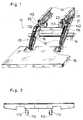
- the tail lift system 10 shown in Fig. 1 is thus capable of both lifting a connected to the lifting and folding structure 12 tail lift 15 and for folding up the tail lift 15 from the horizontal position to the vertical and to fold down from the vertical to the horizontal position.
- the tailgate system 10 described below may be one as outlined above, but it may also be one with which only a lifting or lowering function of the liftgate 15 can be effected.
- tail lift system 10 The general structure of the tail lift system 10 is discussed below only to the extent necessary to understand the tail lift system according to the invention.
- the tail lift system 10 shown in Fig. 1 comprises, as I said, essentially a lifting and folding structure 12, which in turn consists of a first structure 14, which in turn is mounted parallel to each other on a vehicle 11 via the fastening elements 20, 21.
- the first and the second structure 13, 14 form together with the fastening elements 20, 21, the second supporting structure 14 additionally together with a folding actuator 17, a parallelogram-shaped structure.
- the substantially plate-shaped tail lift 15 for lifting and lowering a load (shown without load) and rotatably connected for closing a storage space of the vehicle 11.
- a Hubaktuator 16 acts to raise and lower the liftgate 15 together.
- Part of the parallelogram-shaped structures 13, 14 are the respective fastening elements 20, 21, cf. These also the structure 13, 14 also with comprehensive fasteners 20, 21 consist, for example, of flat, sheet-like elements, see. Fig. 1, in which Achsbuchsen 202 for the axes of rotation 132, 162 and 142, 174 are received in a suitable manner.
- the attachment of the fasteners 20, 21 on the support frame 110, 111 can, unlike in the illustration of FIG. 1, also take place via screw-nut connections, if, for example, on the part of the manufacturer of the truck 11 in the support frame 110, 111 suitable Through holes have already been provided for this purpose at the factory. Further discussion of the generic liftgate systems 10 of the prior art as shown in FIG. 1 is not required for further understanding.
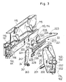
- Fig. 2 shows a very schematic representation of a section through the loading area of a truck 11, omitting all here for the understanding the invention not required details.
- the support elements 110, 111 which form the vehicle frame, spaced from each other.
- the support elements 110, 111 are designed here as so-called hat profiles or double-hat profiles, cf. Also Figs. 3 and 4, as used in particular in trucks 11 of the so-called. 3.5 t class.
- These hat or double-hat profiles have a much smaller profile wall thickness than, for example, the C-profiles described above in connection with FIG. 1, which are regularly used for large trucks of the 10 t to 35 t class.
- the clear distance of the two carrier elements 110, 111 according to FIGS. 2 to 4 is regularly considerably less than the clear distance between the two C-profiles, which form the carrier elements 110, 111 in the truck 11 shown in FIG.
- the carrier elements 110, 111 have respective sides or side surfaces 113, 114, which run substantially vertically to a background, not shown here, on which the truck 11 normally stands or moves, cf. in particular FIGS. 2 and 3.
- An essential part of the tail lift system according to the invention is a matching element 22, which is L-shaped profile or rectangular in cross-section.
- Both legs 220, 221 of the adapter 22 have a plurality of mounting holes 223; 224 on.
- the mounting holes 224 may be provided on the leg 221 in the form of a grid, so that in the subsequent assembly, which will be discussed in more detail below, the respective suitable mounting hole 224 can be used.
- the leg 220 shown in the figures as the upper leg is referred to below as the first leg 220, whereas the right-angled leg 221 is referred to in the following second leg.
- the first leg 220 has at its free end 225 a plurality of holding webs 226 projecting substantially at right angles to the first leg 220.
- first leg 220 can also be angled to form a single retaining web 226, as far as this is structurally possible on the part of the support elements 110, 111, at which the matching element 22 is to be fastened in each case.
- the AnpaBelement 22, see. 3 and 4 has at the free end 227 of the second, vertically formed leg 221 a plurality of substantially at an angle to the second leg 221 projecting support webs 228.
- the support elements 110, 111 it is possible, as far as the respective design of the support elements 110, 111 to be equipped with the tail lift system 10 allow this constructive, instead of a plurality of support webs 228 a support web 228 according to the length and possibly existing Fixing holes in the support members 110, 111 as a unitary support member 228 continuously form.
- the support webs 228 have respective holes 230 at their free ends 229. About these holes 230, the support webs 228 with the support members 11, 12 are connectable.
- a support element 24 which supports the fastening element 20, 21 relative to the carrier elements 110, 111 when it rests against said carrier elements 110, 111, cf. Fig. 4, by suitable connecting means 26, for example.
- Bolt-bolt connections or bolt-nut connections is attached.
- the support member 24 shown in Figs. 3 and 4 here has a substantially angular structure, but it should be noted that for this support function of the support member 24, other structural configurations of the support member 24, for example. In the form of a pipe or a suitable profiled element, are possible.
- the leg 242 of the angular support element 24 shown here can be attached to the support members 110, 111 via there, if necessary factory provided mounting holes that normally serve to receive a crossbeam between the support members 110, 111, then then, for example. A ball coupling for trailers is trained.
- the other leg 243 of the support element 24 is provided with a guide body 245, wherein the guide body 245 can detachably engage in a guide element 200 formed on the fastening element 20, which is designed in the form of an axially slotted tube.
- the tubular guide element 200 is, for example, attached to the fastening element 20, 21, for example by means of a welded connection.
- the slotted tube 201 of the guide member 20 can not only a supporting connection between the support member 24 and the fastener 20, 21 are provided, but also a non-positive connection, if, for example, the guide body 245 is radially spreadable, ie, if necessary, slightly conical and is constructed so that when screwing in a screw 246th c. 4, the diameter of the guide body 245 is increased and thus a frictional connection between the guide body 245 and guide element 200 is produced.
- These support leg members 115 regularly have a horizontally extending support portion 116 which is formed at least partially flat.
- the first leg 220 is placed during assembly of the L-shaped fitting element 22 and fixed there by means of connecting means, for example. Screw bolt connections or screw-nut connections, said connecting means in Figs 3 and 4 are not visible due to the perspective views.
- Fig. 3 but in the extended state of the individual components of the tail lift system 10 according to the invention in the L-shaped fitting element 22 shown there is seen that there are provided on the upper leg 220 mounting holes 223 through which the connecting means can reach through.
- leg-shaped holding webs 226 are on demand over there formed holes with connecting means 28 in the form of bolt-bolt connections or screw-nut connections connected, see. Fig. 4.
- the support webs 228 of AnpaB elements 22 may, for example, at least partially with the same bolt-nut connections or bolt connections, which also for attachment of the support member 24, are connected to the support members 110, 111, see. 4, the fastening elements 20, 21 are connected to the adapter element 22 by first the respective guide elements 200 of the one and the other fastening element 20, 21 is respectively pushed onto the guide body of the support element 24, cf. Fig. 4, and there are suitably positioned. Subsequently, the respective fastener 20, 21 via connecting means 27, for example. In the form of screw-nut connections or bolt connections, connected to the second leg 224 of the Anpgresettis 22, via the appropriately selected mounting holes 224, the second Leg 221 of the matching element 22 are formed.
- the tail lift system 10 also formed in the form of hat or double-hat carrier profiles support frame, which form the support members 110, 111 in trucks of the 3.5 t type, as well simply possible as in large trucks 11, which have massive and regular C-shaped support members 110, 111 have.
Landscapes
- Engineering & Computer Science (AREA)
- Transportation (AREA)
- Mechanical Engineering (AREA)
- Body Structure For Vehicles (AREA)
- Fittings On The Vehicle Exterior For Carrying Loads, And Devices For Holding Or Mounting Articles (AREA)
- Forklifts And Lifting Vehicles (AREA)
Priority Applications (3)
| Application Number | Priority Date | Filing Date | Title |
|---|---|---|---|
| DE502005005961T DE502005005961D1 (de) | 2005-09-16 | 2005-09-16 | Ladebordwandsystem zur Befestigung an Rahmen von Fahrzeugen |
| AT05020221T ATE413984T1 (de) | 2005-09-16 | 2005-09-16 | Ladebordwandsystem zur befestigung an rahmen von fahrzeugen |
| EP05020221A EP1764263B1 (fr) | 2005-09-16 | 2005-09-16 | Système de hayon élévateur pour fixer sur un chassis de véhicule |
Applications Claiming Priority (1)
| Application Number | Priority Date | Filing Date | Title |
|---|---|---|---|
| EP05020221A EP1764263B1 (fr) | 2005-09-16 | 2005-09-16 | Système de hayon élévateur pour fixer sur un chassis de véhicule |
Publications (2)
| Publication Number | Publication Date |
|---|---|
| EP1764263A1 true EP1764263A1 (fr) | 2007-03-21 |
| EP1764263B1 EP1764263B1 (fr) | 2008-11-12 |
Family
ID=35432009
Family Applications (1)
| Application Number | Title | Priority Date | Filing Date |
|---|---|---|---|
| EP05020221A Expired - Lifetime EP1764263B1 (fr) | 2005-09-16 | 2005-09-16 | Système de hayon élévateur pour fixer sur un chassis de véhicule |
Country Status (3)
| Country | Link |
|---|---|
| EP (1) | EP1764263B1 (fr) |
| AT (1) | ATE413984T1 (fr) |
| DE (1) | DE502005005961D1 (fr) |
Citations (7)
| Publication number | Priority date | Publication date | Assignee | Title |
|---|---|---|---|---|
| US2725152A (en) * | 1951-09-13 | 1955-11-29 | Gar Wood Ind Inc | Elevating tail gate for vehicles |
| US2792135A (en) * | 1955-01-12 | 1957-05-14 | L A Young Spring & Wire Corp | Power-operated tail gate |
| EP0805069A1 (fr) * | 1996-05-04 | 1997-11-05 | Gerd Bär GmbH | Dispositif d'assemblage pour un hayon élévatrice |
| EP0808747A1 (fr) * | 1996-05-21 | 1997-11-26 | Sörensen Hydraulik | Système de hayon élévateur |
| DE20009019U1 (de) * | 2000-05-18 | 2000-07-27 | M.H.J. Behrens GmbH, 21465 Wentorf | Vorrichtung zum Befestigen eines Hubwerkes an einem Kraftfahrzeug |
| EP1036698A1 (fr) * | 1999-03-16 | 2000-09-20 | Dautel Campisa S.r.l. | Hayon élévateur avec éléments interchangeables |
| DE202004014724U1 (de) * | 2004-09-22 | 2004-12-23 | Bär, Gerd | Montageadapter für Hubladebühnen |
-
2005
- 2005-09-16 DE DE502005005961T patent/DE502005005961D1/de not_active Expired - Fee Related
- 2005-09-16 AT AT05020221T patent/ATE413984T1/de not_active IP Right Cessation
- 2005-09-16 EP EP05020221A patent/EP1764263B1/fr not_active Expired - Lifetime
Patent Citations (7)
| Publication number | Priority date | Publication date | Assignee | Title |
|---|---|---|---|---|
| US2725152A (en) * | 1951-09-13 | 1955-11-29 | Gar Wood Ind Inc | Elevating tail gate for vehicles |
| US2792135A (en) * | 1955-01-12 | 1957-05-14 | L A Young Spring & Wire Corp | Power-operated tail gate |
| EP0805069A1 (fr) * | 1996-05-04 | 1997-11-05 | Gerd Bär GmbH | Dispositif d'assemblage pour un hayon élévatrice |
| EP0808747A1 (fr) * | 1996-05-21 | 1997-11-26 | Sörensen Hydraulik | Système de hayon élévateur |
| EP1036698A1 (fr) * | 1999-03-16 | 2000-09-20 | Dautel Campisa S.r.l. | Hayon élévateur avec éléments interchangeables |
| DE20009019U1 (de) * | 2000-05-18 | 2000-07-27 | M.H.J. Behrens GmbH, 21465 Wentorf | Vorrichtung zum Befestigen eines Hubwerkes an einem Kraftfahrzeug |
| DE202004014724U1 (de) * | 2004-09-22 | 2004-12-23 | Bär, Gerd | Montageadapter für Hubladebühnen |
Also Published As
| Publication number | Publication date |
|---|---|
| DE502005005961D1 (de) | 2008-12-24 |
| EP1764263B1 (fr) | 2008-11-12 |
| ATE413984T1 (de) | 2008-11-15 |
Similar Documents
| Publication | Publication Date | Title |
|---|---|---|
| DE2711825A1 (de) | Sattelanhaenger mit selbstladeeinrichtung fuer normcontainer o.dgl. | |
| DE2725770A1 (de) | Anordnung zum befestigen von einrichtungen zur verringerung des luftwiderstandes an landfahrzeugen | |
| DE102011055350A1 (de) | Unterfahrschutz zur Anbringung am Heck eines Lastkraftwagens | |
| EP1162111B1 (fr) | Système de hayon élévateur avec unité de glissement | |
| DE3119837A1 (de) | Breitenverstellbarer rahmen in modulbauweise fuer kippritschen von lastkraftwagen | |
| DE102010007995A1 (de) | Fahrzeugkarosserieaufbau im Bereich zwischen Federbeinaufnahmen und Scheibenquerträger sowie zugeordnetes Fertigungsverfahren | |
| EP2269895A2 (fr) | Remorque | |
| EP3348455B1 (fr) | Structure de support pour un véhicule utilitaire non entraîné | |
| EP1764263B1 (fr) | Système de hayon élévateur pour fixer sur un chassis de véhicule | |
| EP0337011A1 (fr) | Dispositif porteur avec éléments de verrouillage pour poser et fixer des plate-formes interchangeables sur un châssis de véhicule | |
| EP1775158B1 (fr) | Système de hayon élévateur pour fixer sur un chassis auxiliaire de véhicule | |
| EP3290308B1 (fr) | Dispositif de fixation et d'appui et remorque | |
| EP0979755B1 (fr) | Hayon élévateur | |
| EP3293096B1 (fr) | Bati porteur pour une superstructure de vehicule utilitaire et montant pour un tel bati porteur | |
| EP2384928B2 (fr) | Hayon élévateur | |
| EP1232903B1 (fr) | Dispositif pour la fixation de systèmes d'hayon élévateur au système de cadre de châssis de remorques, de semi remorques et de véhicules | |
| DE102015108229A1 (de) | Zuggabel für ein Anhängerfahrzeug | |
| DE2728963C3 (de) | Runge für Lastkraftwagen und Anhänger | |
| EP4484216B1 (fr) | Remorque pour le transport de conteneurs | |
| DE19935778B4 (de) | Deichselanordnung | |
| DE102010026356A1 (de) | Fahrgestellrahmen für ein Wechselbrückenfahrzeug | |
| EP1925537A1 (fr) | Structure, en particulier structure à bascule pour une remorque ainsi que remorque | |
| EP1281568B1 (fr) | Fixation d'un hayon élévateur sur un véhicule | |
| DE20102773U1 (de) | Einrichtung zur Befestigung von Ladebordwandsystemen am Chassis-Rahmensystem von Anhängern, Sattelaufliegern und Fahrzeugen | |
| DE202016006868U1 (de) | Anhänger mit geringem Gewicht und ausgezeichneter Ladungssicherheit im Verkehr zur lagesicheren Beförderung von Fertiggaragen |
Legal Events
| Date | Code | Title | Description |
|---|---|---|---|
| PUAI | Public reference made under article 153(3) epc to a published international application that has entered the european phase |
Free format text: ORIGINAL CODE: 0009012 |
|
| 17P | Request for examination filed |
Effective date: 20050927 |
|
| AK | Designated contracting states |
Kind code of ref document: A1 Designated state(s): AT BE BG CH CY CZ DE DK EE ES FI FR GB GR HU IE IS IT LI LT LU LV MC NL PL PT RO SE SI SK TR |
|
| AX | Request for extension of the european patent |
Extension state: AL BA HR MK YU |
|
| AKX | Designation fees paid |
Designated state(s): AT BE BG CH CY CZ DE DK EE ES FI FR GB GR HU IE IS IT LI LT LU LV MC NL PL PT RO SE SI SK TR |
|
| AXX | Extension fees paid |
Extension state: MK Payment date: 20050927 Extension state: AL Payment date: 20050927 Extension state: YU Payment date: 20050927 Extension state: HR Payment date: 20050927 Extension state: BA Payment date: 20050927 |
|
| GRAP | Despatch of communication of intention to grant a patent |
Free format text: ORIGINAL CODE: EPIDOSNIGR1 |
|
| GRAS | Grant fee paid |
Free format text: ORIGINAL CODE: EPIDOSNIGR3 |
|
| GRAA | (expected) grant |
Free format text: ORIGINAL CODE: 0009210 |
|
| AK | Designated contracting states |
Kind code of ref document: B1 Designated state(s): AT BE BG CH CY CZ DE DK EE ES FI FR GB GR HU IE IS IT LI LT LU LV MC NL PL PT RO SE SI SK TR |
|
| AX | Request for extension of the european patent |
Extension state: AL BA HR MK YU |
|
| REG | Reference to a national code |
Ref country code: GB Ref legal event code: FG4D Free format text: NOT ENGLISH |
|
| REG | Reference to a national code |
Ref country code: CH Ref legal event code: EP |
|
| REG | Reference to a national code |
Ref country code: IE Ref legal event code: FG4D Free format text: LANGUAGE OF EP DOCUMENT: GERMAN |
|
| REF | Corresponds to: |
Ref document number: 502005005961 Country of ref document: DE Date of ref document: 20081224 Kind code of ref document: P |
|
| LTIE | Lt: invalidation of european patent or patent extension |
Effective date: 20081112 |
|
| PG25 | Lapsed in a contracting state [announced via postgrant information from national office to epo] |
Ref country code: LT Free format text: LAPSE BECAUSE OF FAILURE TO SUBMIT A TRANSLATION OF THE DESCRIPTION OR TO PAY THE FEE WITHIN THE PRESCRIBED TIME-LIMIT Effective date: 20081112 Ref country code: ES Free format text: LAPSE BECAUSE OF FAILURE TO SUBMIT A TRANSLATION OF THE DESCRIPTION OR TO PAY THE FEE WITHIN THE PRESCRIBED TIME-LIMIT Effective date: 20090223 |
|
| NLV1 | Nl: lapsed or annulled due to failure to fulfill the requirements of art. 29p and 29m of the patents act | ||
| PG25 | Lapsed in a contracting state [announced via postgrant information from national office to epo] |
Ref country code: IS Free format text: LAPSE BECAUSE OF FAILURE TO SUBMIT A TRANSLATION OF THE DESCRIPTION OR TO PAY THE FEE WITHIN THE PRESCRIBED TIME-LIMIT Effective date: 20090312 Ref country code: NL Free format text: LAPSE BECAUSE OF FAILURE TO SUBMIT A TRANSLATION OF THE DESCRIPTION OR TO PAY THE FEE WITHIN THE PRESCRIBED TIME-LIMIT Effective date: 20081112 Ref country code: SI Free format text: LAPSE BECAUSE OF FAILURE TO SUBMIT A TRANSLATION OF THE DESCRIPTION OR TO PAY THE FEE WITHIN THE PRESCRIBED TIME-LIMIT Effective date: 20081112 Ref country code: PL Free format text: LAPSE BECAUSE OF FAILURE TO SUBMIT A TRANSLATION OF THE DESCRIPTION OR TO PAY THE FEE WITHIN THE PRESCRIBED TIME-LIMIT Effective date: 20081112 Ref country code: LV Free format text: LAPSE BECAUSE OF FAILURE TO SUBMIT A TRANSLATION OF THE DESCRIPTION OR TO PAY THE FEE WITHIN THE PRESCRIBED TIME-LIMIT Effective date: 20081112 Ref country code: FI Free format text: LAPSE BECAUSE OF FAILURE TO SUBMIT A TRANSLATION OF THE DESCRIPTION OR TO PAY THE FEE WITHIN THE PRESCRIBED TIME-LIMIT Effective date: 20081112 |
|
| REG | Reference to a national code |
Ref country code: IE Ref legal event code: FD4D |
|
| PG25 | Lapsed in a contracting state [announced via postgrant information from national office to epo] |
Ref country code: IE Free format text: LAPSE BECAUSE OF FAILURE TO SUBMIT A TRANSLATION OF THE DESCRIPTION OR TO PAY THE FEE WITHIN THE PRESCRIBED TIME-LIMIT Effective date: 20081112 Ref country code: EE Free format text: LAPSE BECAUSE OF FAILURE TO SUBMIT A TRANSLATION OF THE DESCRIPTION OR TO PAY THE FEE WITHIN THE PRESCRIBED TIME-LIMIT Effective date: 20081112 Ref country code: RO Free format text: LAPSE BECAUSE OF FAILURE TO SUBMIT A TRANSLATION OF THE DESCRIPTION OR TO PAY THE FEE WITHIN THE PRESCRIBED TIME-LIMIT Effective date: 20081112 Ref country code: BG Free format text: LAPSE BECAUSE OF FAILURE TO SUBMIT A TRANSLATION OF THE DESCRIPTION OR TO PAY THE FEE WITHIN THE PRESCRIBED TIME-LIMIT Effective date: 20090212 Ref country code: DK Free format text: LAPSE BECAUSE OF FAILURE TO SUBMIT A TRANSLATION OF THE DESCRIPTION OR TO PAY THE FEE WITHIN THE PRESCRIBED TIME-LIMIT Effective date: 20081112 |
|
| PG25 | Lapsed in a contracting state [announced via postgrant information from national office to epo] |
Ref country code: SE Free format text: LAPSE BECAUSE OF FAILURE TO SUBMIT A TRANSLATION OF THE DESCRIPTION OR TO PAY THE FEE WITHIN THE PRESCRIBED TIME-LIMIT Effective date: 20090212 Ref country code: PT Free format text: LAPSE BECAUSE OF FAILURE TO SUBMIT A TRANSLATION OF THE DESCRIPTION OR TO PAY THE FEE WITHIN THE PRESCRIBED TIME-LIMIT Effective date: 20090413 Ref country code: CZ Free format text: LAPSE BECAUSE OF FAILURE TO SUBMIT A TRANSLATION OF THE DESCRIPTION OR TO PAY THE FEE WITHIN THE PRESCRIBED TIME-LIMIT Effective date: 20081112 |
|
| PLBE | No opposition filed within time limit |
Free format text: ORIGINAL CODE: 0009261 |
|
| STAA | Information on the status of an ep patent application or granted ep patent |
Free format text: STATUS: NO OPPOSITION FILED WITHIN TIME LIMIT |
|
| PG25 | Lapsed in a contracting state [announced via postgrant information from national office to epo] |
Ref country code: SK Free format text: LAPSE BECAUSE OF FAILURE TO SUBMIT A TRANSLATION OF THE DESCRIPTION OR TO PAY THE FEE WITHIN THE PRESCRIBED TIME-LIMIT Effective date: 20081112 |
|
| 26N | No opposition filed |
Effective date: 20090813 |
|
| BERE | Be: lapsed |
Owner name: SORENSEN HYDRAULIK, ZWEIGNIEDERLASSUNG, ULFBORG, Effective date: 20090930 |
|
| PG25 | Lapsed in a contracting state [announced via postgrant information from national office to epo] |
Ref country code: MC Free format text: LAPSE BECAUSE OF NON-PAYMENT OF DUE FEES Effective date: 20090930 |
|
| REG | Reference to a national code |
Ref country code: CH Ref legal event code: PL |
|
| GBPC | Gb: european patent ceased through non-payment of renewal fee |
Effective date: 20090916 |
|
| REG | Reference to a national code |
Ref country code: FR Ref legal event code: ST Effective date: 20100531 |
|
| PG25 | Lapsed in a contracting state [announced via postgrant information from national office to epo] |
Ref country code: FR Free format text: LAPSE BECAUSE OF NON-PAYMENT OF DUE FEES Effective date: 20090930 Ref country code: DE Free format text: LAPSE BECAUSE OF NON-PAYMENT OF DUE FEES Effective date: 20100401 |
|
| PG25 | Lapsed in a contracting state [announced via postgrant information from national office to epo] |
Ref country code: BE Free format text: LAPSE BECAUSE OF NON-PAYMENT OF DUE FEES Effective date: 20090930 |
|
| PG25 | Lapsed in a contracting state [announced via postgrant information from national office to epo] |
Ref country code: CH Free format text: LAPSE BECAUSE OF NON-PAYMENT OF DUE FEES Effective date: 20090930 Ref country code: GR Free format text: LAPSE BECAUSE OF FAILURE TO SUBMIT A TRANSLATION OF THE DESCRIPTION OR TO PAY THE FEE WITHIN THE PRESCRIBED TIME-LIMIT Effective date: 20090213 Ref country code: LI Free format text: LAPSE BECAUSE OF NON-PAYMENT OF DUE FEES Effective date: 20090930 |
|
| PG25 | Lapsed in a contracting state [announced via postgrant information from national office to epo] |
Ref country code: GB Free format text: LAPSE BECAUSE OF NON-PAYMENT OF DUE FEES Effective date: 20090916 Ref country code: AT Free format text: LAPSE BECAUSE OF NON-PAYMENT OF DUE FEES Effective date: 20090916 |
|
| PG25 | Lapsed in a contracting state [announced via postgrant information from national office to epo] |
Ref country code: IT Free format text: LAPSE BECAUSE OF FAILURE TO SUBMIT A TRANSLATION OF THE DESCRIPTION OR TO PAY THE FEE WITHIN THE PRESCRIBED TIME-LIMIT Effective date: 20081112 |
|
| PG25 | Lapsed in a contracting state [announced via postgrant information from national office to epo] |
Ref country code: LU Free format text: LAPSE BECAUSE OF NON-PAYMENT OF DUE FEES Effective date: 20090916 |
|
| PG25 | Lapsed in a contracting state [announced via postgrant information from national office to epo] |
Ref country code: HU Free format text: LAPSE BECAUSE OF FAILURE TO SUBMIT A TRANSLATION OF THE DESCRIPTION OR TO PAY THE FEE WITHIN THE PRESCRIBED TIME-LIMIT Effective date: 20090513 |
|
| PG25 | Lapsed in a contracting state [announced via postgrant information from national office to epo] |
Ref country code: TR Free format text: LAPSE BECAUSE OF FAILURE TO SUBMIT A TRANSLATION OF THE DESCRIPTION OR TO PAY THE FEE WITHIN THE PRESCRIBED TIME-LIMIT Effective date: 20081112 |
|
| PG25 | Lapsed in a contracting state [announced via postgrant information from national office to epo] |
Ref country code: CY Free format text: LAPSE BECAUSE OF FAILURE TO SUBMIT A TRANSLATION OF THE DESCRIPTION OR TO PAY THE FEE WITHIN THE PRESCRIBED TIME-LIMIT Effective date: 20081112 |