EP1764320A1 - Pipe convoyeur pour le transport pneumatique simplifié - Google Patents
Pipe convoyeur pour le transport pneumatique simplifié Download PDFInfo
- Publication number
- EP1764320A1 EP1764320A1 EP05020122A EP05020122A EP1764320A1 EP 1764320 A1 EP1764320 A1 EP 1764320A1 EP 05020122 A EP05020122 A EP 05020122A EP 05020122 A EP05020122 A EP 05020122A EP 1764320 A1 EP1764320 A1 EP 1764320A1
- Authority
- EP
- European Patent Office
- Prior art keywords
- pneumatic conveying
- conveying pipe
- shell
- pipe according
- intermediate bottom
- Prior art date
- Legal status (The legal status is an assumption and is not a legal conclusion. Google has not performed a legal analysis and makes no representation as to the accuracy of the status listed.)
- Withdrawn
Links
- 239000002184 metal Substances 0.000 claims abstract description 18
- 239000013590 bulk material Substances 0.000 claims description 19
- 239000004744 fabric Substances 0.000 claims description 18
- 238000007789 sealing Methods 0.000 claims description 13
- 230000000295 complement effect Effects 0.000 claims description 3
- 238000003780 insertion Methods 0.000 claims description 2
- 230000037431 insertion Effects 0.000 claims description 2
- 238000005192 partition Methods 0.000 abstract 1
- 239000000843 powder Substances 0.000 abstract 1
- 238000009420 retrofitting Methods 0.000 description 8
- 230000008901 benefit Effects 0.000 description 7
- 238000005243 fluidization Methods 0.000 description 5
- 238000010276 construction Methods 0.000 description 4
- 238000004519 manufacturing process Methods 0.000 description 4
- 239000000463 material Substances 0.000 description 4
- 238000013461 design Methods 0.000 description 3
- 238000009826 distribution Methods 0.000 description 3
- 238000009434 installation Methods 0.000 description 3
- 230000002349 favourable effect Effects 0.000 description 2
- 239000007769 metal material Substances 0.000 description 2
- 230000000284 resting effect Effects 0.000 description 2
- 238000009423 ventilation Methods 0.000 description 2
- 206010012735 Diarrhoea Diseases 0.000 description 1
- 230000006978 adaptation Effects 0.000 description 1
- 230000002411 adverse Effects 0.000 description 1
- 238000005273 aeration Methods 0.000 description 1
- 229940125810 compound 20 Drugs 0.000 description 1
- 150000001875 compounds Chemical class 0.000 description 1
- 230000001419 dependent effect Effects 0.000 description 1
- 238000011161 development Methods 0.000 description 1
- 230000018109 developmental process Effects 0.000 description 1
- JAXFJECJQZDFJS-XHEPKHHKSA-N gtpl8555 Chemical compound OC(=O)C[C@H](N)C(=O)N[C@@H](CCC(O)=O)C(=O)N[C@@H](C(C)C)C(=O)N[C@@H](C(C)C)C(=O)N1CCC[C@@H]1C(=O)N[C@H](B1O[C@@]2(C)[C@H]3C[C@H](C3(C)C)C[C@H]2O1)CCC1=CC=C(F)C=C1 JAXFJECJQZDFJS-XHEPKHHKSA-N 0.000 description 1
- 239000007788 liquid Substances 0.000 description 1
- 238000000034 method Methods 0.000 description 1
- 230000005012 migration Effects 0.000 description 1
- 238000013508 migration Methods 0.000 description 1
- 230000035699 permeability Effects 0.000 description 1
- 238000002360 preparation method Methods 0.000 description 1
- 230000008569 process Effects 0.000 description 1
- 239000003380 propellant Substances 0.000 description 1
- 239000007787 solid Substances 0.000 description 1
- 230000007704 transition Effects 0.000 description 1
Images

Classifications
-
- B—PERFORMING OPERATIONS; TRANSPORTING
- B65—CONVEYING; PACKING; STORING; HANDLING THIN OR FILAMENTARY MATERIAL
- B65G—TRANSPORT OR STORAGE DEVICES, e.g. CONVEYORS FOR LOADING OR TIPPING, SHOP CONVEYOR SYSTEMS OR PNEUMATIC TUBE CONVEYORS
- B65G53/00—Conveying materials in bulk through troughs, pipes or tubes by floating the materials or by flow of gas, liquid or foam
- B65G53/04—Conveying materials in bulk pneumatically through pipes or tubes; Air slides
- B65G53/16—Gas pressure systems operating with fluidisation of the materials
- B65G53/18—Gas pressure systems operating with fluidisation of the materials through a porous wall
- B65G53/20—Gas pressure systems operating with fluidisation of the materials through a porous wall of an air slide, e.g. a trough
Definitions
- the invention relates to a pneumatic conveying tube for transporting bulk material with a tubular housing which is divided by an intermediate bottom into an upper conveying space and a lower gas space, wherein sealing strips are provided for sealing attachment of the side edges of the intermediate bottom.
- pneumatic conveying devices are often used. They enable a simple, energy-efficient and dust-free transport of the bulk material when closed.
- the air conveyor trough can be open or closed. It has along its length in the lower part of a ventilation floor. Through this compressed gas is supplied during operation, which flows through the bulk material. In the process, the boundary layer between bulk material and aeration bottom is loosened up, as a result of which the bulk material no longer rests, but rather like a liquid can be displaced almost without friction.
- the driving force for the transport of the thus fluidized bulk material results from the arrangement in a slight slope.
- the air conveyor trough is therefore only suitable for transporting the goods in the downward direction.
- the other basic type is the pneumatic conveying pipe.
- the difference to the conveyor trough no gradient in the conveying direction is required, but the transport of the bulk material is usually carried out by pressure or suction along the conveyor pipe.
- an overpressure can be applied at the beginning of the conveyor tube, or it is accordingly sucked at the end of the conveyor tube with a negative pressure.
- This design has the advantage that it is position-independent. Fluidization is not necessarily required along the entire pipe length in this type, but it is usually sufficient in sections, the ventilation floors ( WO-A-03/026991 ).
- the top can be designed as a sintered plate, but thus increases the production cost, also turns when integrating the porous plate in the tubing again the problem of ensuring a sufficient tightness.
- the supply of fluidizing gas into the tube is difficult. Although it can be done on its front sides, but then results in a different pressure distribution along the conveyor pipe. If the delivery of the fluidizing gas takes place in sections from below through the delivery pipe, then corresponding connecting pieces must be formed on the hose material. Due to unavoidable creeping and migration movement of the hose there is a risk of tearing off the nozzles, in particular on the sharp edges of the openings in the conveyor pipe. Overall, the tube solution can not satisfy with the occurring in practice harsh operating conditions. This construction has therefore not enforced in practice.
- the invention is based on the object on the basis of the first-mentioned prior art, a pneumatic conveying pipe of the type mentioned in order to improve that it is easier to assemble and has greater operational safety.
- a pneumatic conveying pipe for transporting bulk material having a tubular housing which is divided by an intermediate floor in an upper conveying space and a lower gas space, wherein the intermediate bottom is sealed by running along its side edges fasteners, that the up through the intermediate floor limited gas space to the side and downwards is limited by a rigid shell, with the edges of the fasteners for the false floor are connected.
- the core of the invention is the idea to create a rigid shell with an inner housing that limits the gas space and at the same time forms a mounting frame for the false floor. It is thus created a self-sufficient inner housing for the gas space, which is sealed in and does not need to be sealed transitions to the inner wall of the delivery pipe.
- the assembly can thus be done in an extremely simple manner. It is only necessary to insert the shell with the intermediate bottom as an inner housing in the conveying pipe. The production of a fastening or lateral seal to the inner wall of the tube is eliminated.
- the invention thus enables a modular design that allows to form by means of prefabricated components of a conventional conduit a pneumatic conveying pipe. So it can be used conventional tubes. These are not only inexpensive, but continue to have the Advantage of easy retrofitting. It can be easily retrofitted existing pipe systems with the inner housing according to the invention. This need not be done along the entire conveyor line, but it is sufficient in many cases, to provide at certain critical points such an inner housing in order to achieve fluidization. In addition to the ease of installation and retrofitting, the invention can book a further advantage for themselves, namely that with the rigid shell according to the invention an embodiment of the shell as well as the intermediate floor made of metal is possible without separate sealing elements made of sensitive materials such as rubber or tubular fabric required are.
- the metal version offers the advantage of high wear and temperature resistance.
- the intermediate floor may be designed as a rigid plate, but can also be advantageously provided to form it from a fabric material. If the fabric stretched between the edges of the shell, this results in a very inexpensive and good gas permeability intermediate shelf.
- the term plate-like in the sense of this invention should therefore be understood to include not only a solid structure but also a tissue.
- the fabric may be, for example, a gutter fabric or a metal fabric. Wire mesh, in particular of metal, offer the advantage that it is simple and inexpensive to manufacture and has a high temperature and wear resistance. It is expedient to provide a clamping frame for the metal fabric at least on two opposite edges of the shell. Thus, the tissue can be held dimensionally stable.
- the shape of the shell is preferably chosen such that it is complementary to the inner contour of the conveyor tube. This results in a good fit between the shell and the tube. Cavities in which bulk could accumulate in an undesirable manner are avoided in this way. However, this should not exclude that the shell is formed of several angularly assembled bottom and side plates. In order for a trough-like structure can be created that forms a great compromise between favorable production on the one hand and adaptation to the inner contour of the conveyor pipe on the other hand in a structurally simple manner.
- At least one nozzle is designed for supplying compressed gas, which is guided through an opening in the conveying pipe to the outside.
- the pressurized gas required for fluidization can be supplied.
- the arrangement of the opposite intermediate floor makes it possible to arrange the nozzle centrally in the longitudinal direction of the conveying pipe or even to provide a plurality of nozzles. This makes it possible to achieve a more uniform pressure distribution of the fluidizing gas in the gas space. A more even pressure distribution is favorable for a well controllable fluidization.
- the arrangement also has the advantage of easy retrofitting. It only needs to be introduced into a conventional, existing pipe a sufficiently large opening at the bottom.
- the nozzle is then either pushed from the inside when inserting the shell, or it can also be provided to introduce it from the outside into the shell and to connect with this (eg. By means of a thread).
- an elastic element is placed on the neck. Its outer diameter is suitably matched to the width of the opening in the delivery pipe, on the one hand, a seal and on the other hand, a secure mounting of the shell results in their position.
- the invention is also suitable for retrofitting existing conveying pipes in order to allow fluidization of the bulk material to be transported.
- a retrofit kit for pneumatic conveying for transporting bulk material is provided with an inner housing for insertion into a tubular housing of the conveying tube, which is divided by an intermediate bottom in an upper conveying space and in a lower gas space, wherein the inner housing is formed as a rigid shell which is covered at the top by the intermediate bottom, which is connected via fastening elements with the edges of the rigid shell.
- This retrofit kit is particularly suitable for retrofitting existing conveyor tubes, since no cumbersome mounting or sealing work inside the conveyor tube are made. It is sufficient to insert the inner housing according to the invention from the pipe end into the conveying pipe.
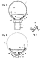
- the pneumatic conveying tube comprises a cylindrical tube housing 1 with a fluidizing device, which is formed by an inner housing 2 with a connecting piece 3.
- the inner housing 2 consists essentially of a shell 22 and a plate 21 as an intermediate floor.
- the plate 21 is a metal plate provided with a plurality of fine holes (not shown). The width of the openings is dimensioned so that an undesirable diarrhea of resting on the plate 21 bulk material is prevented.
- the shell 22 is of the general shape of a portion of a cylinder shell. It is adapted with its outer contour to the inner wall of the tube 1.
- the shell 22 lies in the lower region of the tube 1 in such a way that the plate 21 forms a secant, which is horizontal in section.
- the shell 22 is connected to the bottom 21 along its longitudinal sides (viewed in the axial direction of the tube 1) via a welded joint 20 tightly connected to each other.
- the welded joint 20 alone connects the plate 21 with the Shell 22; a connection with the tube 1 is not provided.
- a closed inner housing 2 is formed, which encloses a gas space 29.
- the gas space gas for example. Compressed air supplied. Due to the pressure difference, gas flows through the openings of the plate 21 from the gas space 29 into the delivery space 19. Bulk material resting on the plate 21 is fluidized.
- the inner housing 2 with the shell 22 and the plate 21 is preferably made of metal material.
- the use of metallic materials allows higher temperatures during transport of the bulk material. While temperatures of up to 150 ° C have conventionally been achieved in the prior art, temperatures of 200 ° C to 400 ° C are readily achieved thanks to the invention in a metallic design.
- a nozzle 3 For supplying gas into the gas space 29, a nozzle 3 is provided. It consists essentially of a main pipe 30 through which compressed air is passed as compressed gas. The main pipe 30 is passed through an opening 13 in the pipe 1. This has a wide, which is slightly larger than that of the main tube 30, to allow easy passage. To seal the opening 13 from the environment, a seal 33 is provided. This seal is designed as a flat disc seal which is arranged around the inside end of the main tube 30 and pressed by the shell 22 against the inner wall of the tube 1.
- a weld or a screw thread connection may be provided. The latter is particularly suitable for retrofitting or long nozzles. With short nozzles it is also possible to use the entire assembly from shell 22 with nozzle 3 into the tube 1, until the nozzle 3 are located above their respective openings 13, and then lower the inner housing 2 so far that the nozzle 3 exit from the opening 13.
- a second embodiment is shown. It differs from that shown in Fig. 1 essentially in that instead of the plate 21, a metal fabric 21 'is used as an intermediate floor. Another difference is that, instead of the shell 22 adapted to the inner contour of the tube 1, a shell body 22 'composed of a plurality of straight plates is used.
- connecting elements 20 ' are provided, which connect the shell body 22' with the functioning as an intermediate bottom metal fabric 21 'sealing.
- connection 20 ' The construction of the connection 20 'is shown in more detail in FIG.
- the intermediate fabric 21' is angled so that it runs parallel to the outer portion of the side panels 24 '.
- the intermediate fabric 21' In this area, along the side edges sealing strips 26 'placed on the metal fabric 21', and by means of a screw 27 'as a tensile compound firmly on the metal fabric 21' and the outer region of the side plates 24 'pressed.
- the metal fabric 21 ' is stretched over the shell body 22'.
- the compound 20 'thus holds the metal fabric 21' mechanically and at the same time seals it against the shell body 22 '.
- the connection by means of screw elements 27 'or rivets makes it possible to connect the shell body 22' with the metal fabric 21 'already outside the tube 1, and to insert the thus prepared inner housing into the tube 1. This embodiment is thus ideal for retrofitting.
- a nozzle 3 ' For supplying compressed gas, in turn, a nozzle 3 'is provided. Its main tube 30 'is guided over a rubber sleeve 33' by a matched to the outer diameter of the rubber sleeve 33 'opening 13' in the tube 1, and terminates in an opening in the bottom plate 23 'of the shell body 22'. Preferably, this is the main tube 30 'to the bottom plate 23' welded. This allows a particularly secure sealing connection. But it can also be provided that the tube 30 'via a corresponding threaded connection (not shown) in the bottom plate 23' is screwed.
- the sleeve 33 'does not serve to seal against the pressure of the gas supply, but isolates the delivery chamber 19 from the environment. On special gas-tightness, it is therefore not regularly on her.
- Fig. 4 the embodiment shown in Fig. 2 is shown in a longitudinal view. Similar parts are provided with the same reference numerals, so that in this respect can be omitted explanation here.
- the reference numeral 25 ' denotes end walls of the shell body 22'. They limit the shell body 22 'forward and backward.
- the connection with the metal fabric 21 ' is made in a manner corresponding to the side edges.
- FIGS. 2 and 4 are suitable for retrofitting existing conveying pipes. It need in the interior of the conveyor pipe 1 no work to be done, but it is sufficient to create an opening 13 for the implementation of the connecting piece 30 '.
- the inner housing with the already sealingly connected together shell 22 'and intermediate bottom 21 then needs to be inserted only from the side, until the connecting pieces 30 'are above the respective openings 13 and then lowered into position. The fixation takes place via the connecting piece 30 '.
- flat gaskets are preferably used on the connecting piece 30 '. You only need to be connected to a gas source (not shown), and the conventional pneumatic conveying pipe is upgraded with the retrofit kit according to the invention to a pneumatic conveying tube with fluidizing.
- Fig. 5 the arrangement of the inner housing is shown in a longer conveyor pipe 1. It will be appreciated that it is not necessary to arrange an inner housing 2 for fluidizing along the entire route. It is sufficient to arrange it in individual, usually particularly critical sections. An example of this is shown in Fig. 5, the slope shown. With conventional means, this is difficult to overcome for the bulk material. Thanks to the invention, the bulk material can be fluidized so far that it can overcome the slope under the force of a propellant gas stream (symbolized by an arrow).
Landscapes
- Engineering & Computer Science (AREA)
- Mechanical Engineering (AREA)
- Air Transport Of Granular Materials (AREA)
Priority Applications (1)
| Application Number | Priority Date | Filing Date | Title |
|---|---|---|---|
| EP05020122A EP1764320A1 (fr) | 2005-09-15 | 2005-09-15 | Pipe convoyeur pour le transport pneumatique simplifié |
Applications Claiming Priority (1)
| Application Number | Priority Date | Filing Date | Title |
|---|---|---|---|
| EP05020122A EP1764320A1 (fr) | 2005-09-15 | 2005-09-15 | Pipe convoyeur pour le transport pneumatique simplifié |
Publications (1)
| Publication Number | Publication Date |
|---|---|
| EP1764320A1 true EP1764320A1 (fr) | 2007-03-21 |
Family
ID=35791324
Family Applications (1)
| Application Number | Title | Priority Date | Filing Date |
|---|---|---|---|
| EP05020122A Withdrawn EP1764320A1 (fr) | 2005-09-15 | 2005-09-15 | Pipe convoyeur pour le transport pneumatique simplifié |
Country Status (1)
| Country | Link |
|---|---|
| EP (1) | EP1764320A1 (fr) |
Cited By (1)
| Publication number | Priority date | Publication date | Assignee | Title |
|---|---|---|---|---|
| US20210220786A1 (en) * | 2018-06-06 | 2021-07-22 | Glatt Gesellschaft Mit Beschränkter Haftung | Unit and Method for Producing and Treating Granulate, and Adapter Connecting Piece for Connecting a Granulator Which Generates a Granulate and a Fluidizing Apparatus |
Citations (7)
| Publication number | Priority date | Publication date | Assignee | Title |
|---|---|---|---|---|
| FR1491292A (fr) * | 1966-04-29 | 1967-08-11 | Dumont L | Dispositif pour le transport de produits pulvérulents |
| DE1556091A1 (de) | 1967-09-21 | 1970-01-15 | Schloz Motor Condensator | Foerderrinne zum Foerdern von feinkoernigem und pulverfoermigem Gut mittels eines durch eine durchlaessige Platte eingefuehrten gasfoermigen Mediums |
| DE2018742A1 (de) | 1970-04-18 | 1971-11-04 | Claudius Peters Ag, 2000 Hamburg | Pneumatische Förderrinne |
| DE2054912A1 (de) | 1970-11-07 | 1972-05-25 | Peters Ag Claudius | Pneumatische Förderrinne |
| WO2003026991A1 (fr) | 2001-09-21 | 2003-04-03 | Claudius Peters Technologies Gmbh | Dispositif et procede de transport pneumatique |
| US20040191007A1 (en) * | 2001-03-21 | 2004-09-30 | Morten Karlsen | Method and a system for distribution of fluidisable materials |
| EP1623941A1 (fr) * | 2004-08-05 | 2006-02-08 | Alcan Technology & Management Ltd. | Dispositif et procédé de transport pneumatique de produits coulants dans une coulée épaisse |
-
2005
- 2005-09-15 EP EP05020122A patent/EP1764320A1/fr not_active Withdrawn
Patent Citations (7)
| Publication number | Priority date | Publication date | Assignee | Title |
|---|---|---|---|---|
| FR1491292A (fr) * | 1966-04-29 | 1967-08-11 | Dumont L | Dispositif pour le transport de produits pulvérulents |
| DE1556091A1 (de) | 1967-09-21 | 1970-01-15 | Schloz Motor Condensator | Foerderrinne zum Foerdern von feinkoernigem und pulverfoermigem Gut mittels eines durch eine durchlaessige Platte eingefuehrten gasfoermigen Mediums |
| DE2018742A1 (de) | 1970-04-18 | 1971-11-04 | Claudius Peters Ag, 2000 Hamburg | Pneumatische Förderrinne |
| DE2054912A1 (de) | 1970-11-07 | 1972-05-25 | Peters Ag Claudius | Pneumatische Förderrinne |
| US20040191007A1 (en) * | 2001-03-21 | 2004-09-30 | Morten Karlsen | Method and a system for distribution of fluidisable materials |
| WO2003026991A1 (fr) | 2001-09-21 | 2003-04-03 | Claudius Peters Technologies Gmbh | Dispositif et procede de transport pneumatique |
| EP1623941A1 (fr) * | 2004-08-05 | 2006-02-08 | Alcan Technology & Management Ltd. | Dispositif et procédé de transport pneumatique de produits coulants dans une coulée épaisse |
Cited By (2)
| Publication number | Priority date | Publication date | Assignee | Title |
|---|---|---|---|---|
| US20210220786A1 (en) * | 2018-06-06 | 2021-07-22 | Glatt Gesellschaft Mit Beschränkter Haftung | Unit and Method for Producing and Treating Granulate, and Adapter Connecting Piece for Connecting a Granulator Which Generates a Granulate and a Fluidizing Apparatus |
| US12145126B2 (en) * | 2018-06-06 | 2024-11-19 | Glatt Gesellschaft Mit Beschränkter Haftung | Unit and method for producing and treating granulate, and adapter connection piece for connecting a granulator which generates a granulate and a fluidizing apparatus |
Similar Documents
| Publication | Publication Date | Title |
|---|---|---|
| DE69519399T2 (de) | Vorrichtung zum stumpfstossförmigen Verbinden von Gasrohren mit rechteckigem oder quadratischem Querschnitt | |
| DE3839582C1 (fr) | ||
| DD200216A5 (de) | Schlauchfilter fuer die reinigung von gasen | |
| EP4056759A1 (fr) | Finisseuse de route pourvu de dispositif d'aspiration | |
| DE9207094U1 (de) | Vorrichtung zum Begasen von Flüssigkeiten | |
| DE1506848C3 (de) | Rohrleitung für den pneumatischen oder hydraulischen Transport kurzer, gleichartiger Materialpfropfen | |
| EP1020372B1 (fr) | Dispositif de vidange pour récipients contenant des produits pulvérulents | |
| DE4324065A1 (de) | Filter, insbesondere Feinstaub-Entlüftungsfilter | |
| EP3040149B1 (fr) | Dispositif de soudure avec distribution de gaz | |
| DE10102530B4 (de) | Fließbett | |
| EP4272852A1 (fr) | Sac filtrant et module filtrant pour un filtre à disque rotatif et filtre à disque rotatif | |
| DE202005002563U1 (de) | Auslaufeinrichtung | |
| EP1693316A1 (fr) | Dispositif de sortie avec un système de nettoyage | |
| DE2533968C3 (de) | Aus zumindest zwei miteinander verbundenen Rohrschüssen aus thermoplastischen Kunststoff zusammengesetzte Rohrleitung für Kanalsickersysteme | |
| DE102005029033A1 (de) | Verschlußstopfen für ein metallurgisches Schmelzgefäß | |
| DE102009020437A1 (de) | Vorrichtung zum Transportieren von Schüttgütern | |
| DE2934087A1 (de) | Austragsduese | |
| DE2116972C3 (de) | Belüftungseinrichtung für pneumatische Förderanlagen | |
| CH652686A5 (de) | Auslaufeinrichtung an einem silo fuer staub- oder kornfoermiges schuettgut. | |
| DE9315912U1 (de) | Vorrichtung zum dichtschließenden Verbinden eines Kanals mit einem Anschlußrohr | |
| EP1960593A1 (fr) | Languette d'appui deformable pour un tamis et une partie de tamis double | |
| EP2042371B1 (fr) | Trémie de décharge pour un silo d'un véhicule à silo | |
| DE7315271U (de) | Pneumatische Forderrinne | |
| DE69109735T2 (de) | Vorrichtung zum Entnehmen von Gas aus einem Tankbehälter. | |
| DE202022100817U1 (de) | Entwässerungsvorrichtung zum Entwässern des Inneren eines Übergangs für ein Gelenkfahrzeug |
Legal Events
| Date | Code | Title | Description |
|---|---|---|---|
| PUAI | Public reference made under article 153(3) epc to a published international application that has entered the european phase |
Free format text: ORIGINAL CODE: 0009012 |
|
| AK | Designated contracting states |
Kind code of ref document: A1 Designated state(s): AT BE BG CH CY CZ DE DK EE ES FI FR GB GR HU IE IS IT LI LT LU LV MC NL PL PT RO SE SI SK TR |
|
| AX | Request for extension of the european patent |
Extension state: AL BA HR MK YU |
|
| AKX | Designation fees paid | ||
| STAA | Information on the status of an ep patent application or granted ep patent |
Free format text: STATUS: THE APPLICATION IS DEEMED TO BE WITHDRAWN |
|
| 18D | Application deemed to be withdrawn |
Effective date: 20070922 |
|
| REG | Reference to a national code |
Ref country code: DE Ref legal event code: 8566 |