EP1764497B1 - Kraftstoffversorgungssteuervorrichtung für verbrennungsmotor - Google Patents
Kraftstoffversorgungssteuervorrichtung für verbrennungsmotor Download PDFInfo
- Publication number
- EP1764497B1 EP1764497B1 EP05758021.9A EP05758021A EP1764497B1 EP 1764497 B1 EP1764497 B1 EP 1764497B1 EP 05758021 A EP05758021 A EP 05758021A EP 1764497 B1 EP1764497 B1 EP 1764497B1
- Authority
- EP
- European Patent Office
- Prior art keywords
- auxiliary fuel
- fuel
- exhaust
- output
- shortage
- Prior art date
- Legal status (The legal status is an assumption and is not a legal conclusion. Google has not performed a legal analysis and makes no representation as to the accuracy of the status listed.)
- Expired - Lifetime
Links
Images









Classifications
-
- F—MECHANICAL ENGINEERING; LIGHTING; HEATING; WEAPONS; BLASTING
- F02—COMBUSTION ENGINES; HOT-GAS OR COMBUSTION-PRODUCT ENGINE PLANTS
- F02D—CONTROLLING COMBUSTION ENGINES
- F02D41/00—Electrical control of supply of combustible mixture or its constituents
- F02D41/0002—Controlling intake air
- F02D41/0007—Controlling intake air for control of turbo-charged or super-charged engines
-
- F—MECHANICAL ENGINEERING; LIGHTING; HEATING; WEAPONS; BLASTING
- F01—MACHINES OR ENGINES IN GENERAL; ENGINE PLANTS IN GENERAL; STEAM ENGINES
- F01N—GAS-FLOW SILENCERS OR EXHAUST APPARATUS FOR MACHINES OR ENGINES IN GENERAL; GAS-FLOW SILENCERS OR EXHAUST APPARATUS FOR INTERNAL-COMBUSTION ENGINES
- F01N3/00—Exhaust or silencing apparatus having means for purifying, rendering innocuous, or otherwise treating exhaust
- F01N3/08—Exhaust or silencing apparatus having means for purifying, rendering innocuous, or otherwise treating exhaust for rendering innocuous
- F01N3/0807—Exhaust or silencing apparatus having means for purifying, rendering innocuous, or otherwise treating exhaust for rendering innocuous by using absorbents or adsorbents
- F01N3/0828—Exhaust or silencing apparatus having means for purifying, rendering innocuous, or otherwise treating exhaust for rendering innocuous by using absorbents or adsorbents characterised by the absorbed or adsorbed substances
- F01N3/0842—Nitrogen oxides
-
- F—MECHANICAL ENGINEERING; LIGHTING; HEATING; WEAPONS; BLASTING
- F02—COMBUSTION ENGINES; HOT-GAS OR COMBUSTION-PRODUCT ENGINE PLANTS
- F02D—CONTROLLING COMBUSTION ENGINES
- F02D23/00—Controlling engines characterised by their being supercharged
-
- F—MECHANICAL ENGINEERING; LIGHTING; HEATING; WEAPONS; BLASTING
- F02—COMBUSTION ENGINES; HOT-GAS OR COMBUSTION-PRODUCT ENGINE PLANTS
- F02D—CONTROLLING COMBUSTION ENGINES
- F02D41/00—Electrical control of supply of combustible mixture or its constituents
- F02D41/30—Controlling fuel injection
- F02D41/38—Controlling fuel injection of the high pressure type
- F02D41/40—Controlling fuel injection of the high pressure type with means for controlling injection timing or duration
- F02D41/402—Multiple injections
- F02D41/405—Multiple injections with post injections
-
- F—MECHANICAL ENGINEERING; LIGHTING; HEATING; WEAPONS; BLASTING
- F01—MACHINES OR ENGINES IN GENERAL; ENGINE PLANTS IN GENERAL; STEAM ENGINES
- F01N—GAS-FLOW SILENCERS OR EXHAUST APPARATUS FOR MACHINES OR ENGINES IN GENERAL; GAS-FLOW SILENCERS OR EXHAUST APPARATUS FOR INTERNAL-COMBUSTION ENGINES
- F01N2430/00—Influencing exhaust purification, e.g. starting of catalytic reaction, filter regeneration, or the like, by controlling engine operating characteristics
- F01N2430/08—Influencing exhaust purification, e.g. starting of catalytic reaction, filter regeneration, or the like, by controlling engine operating characteristics by modifying ignition or injection timing
- F01N2430/085—Influencing exhaust purification, e.g. starting of catalytic reaction, filter regeneration, or the like, by controlling engine operating characteristics by modifying ignition or injection timing at least a part of the injection taking place during expansion or exhaust stroke
-
- F—MECHANICAL ENGINEERING; LIGHTING; HEATING; WEAPONS; BLASTING
- F01—MACHINES OR ENGINES IN GENERAL; ENGINE PLANTS IN GENERAL; STEAM ENGINES
- F01N—GAS-FLOW SILENCERS OR EXHAUST APPARATUS FOR MACHINES OR ENGINES IN GENERAL; GAS-FLOW SILENCERS OR EXHAUST APPARATUS FOR INTERNAL-COMBUSTION ENGINES
- F01N3/00—Exhaust or silencing apparatus having means for purifying, rendering innocuous, or otherwise treating exhaust
- F01N3/08—Exhaust or silencing apparatus having means for purifying, rendering innocuous, or otherwise treating exhaust for rendering innocuous
- F01N3/0807—Exhaust or silencing apparatus having means for purifying, rendering innocuous, or otherwise treating exhaust for rendering innocuous by using absorbents or adsorbents
- F01N3/0821—Exhaust or silencing apparatus having means for purifying, rendering innocuous, or otherwise treating exhaust for rendering innocuous by using absorbents or adsorbents combined with particulate filter
-
- F—MECHANICAL ENGINEERING; LIGHTING; HEATING; WEAPONS; BLASTING
- F02—COMBUSTION ENGINES; HOT-GAS OR COMBUSTION-PRODUCT ENGINE PLANTS
- F02B—INTERNAL-COMBUSTION PISTON ENGINES; COMBUSTION ENGINES IN GENERAL
- F02B29/00—Engines characterised by provision for charging or scavenging not provided for in groups F02B25/00, F02B27/00 or F02B33/00 - F02B39/00; Details thereof
- F02B29/04—Cooling of air intake supply
- F02B29/0406—Layout of the intake air cooling or coolant circuit
-
- F—MECHANICAL ENGINEERING; LIGHTING; HEATING; WEAPONS; BLASTING
- F02—COMBUSTION ENGINES; HOT-GAS OR COMBUSTION-PRODUCT ENGINE PLANTS
- F02B—INTERNAL-COMBUSTION PISTON ENGINES; COMBUSTION ENGINES IN GENERAL
- F02B37/00—Engines characterised by provision of pumps driven at least for part of the time by exhaust
-
- F—MECHANICAL ENGINEERING; LIGHTING; HEATING; WEAPONS; BLASTING
- F02—COMBUSTION ENGINES; HOT-GAS OR COMBUSTION-PRODUCT ENGINE PLANTS
- F02D—CONTROLLING COMBUSTION ENGINES
- F02D2200/00—Input parameters for engine control
- F02D2200/02—Input parameters for engine control the parameters being related to the engine
- F02D2200/04—Engine intake system parameters
- F02D2200/0406—Intake manifold pressure
-
- F—MECHANICAL ENGINEERING; LIGHTING; HEATING; WEAPONS; BLASTING
- F02—COMBUSTION ENGINES; HOT-GAS OR COMBUSTION-PRODUCT ENGINE PLANTS
- F02D—CONTROLLING COMBUSTION ENGINES
- F02D2200/00—Input parameters for engine control
- F02D2200/02—Input parameters for engine control the parameters being related to the engine
- F02D2200/08—Exhaust gas treatment apparatus parameters
- F02D2200/0812—Particle filter loading
-
- F—MECHANICAL ENGINEERING; LIGHTING; HEATING; WEAPONS; BLASTING
- F02—COMBUSTION ENGINES; HOT-GAS OR COMBUSTION-PRODUCT ENGINE PLANTS
- F02D—CONTROLLING COMBUSTION ENGINES
- F02D41/00—Electrical control of supply of combustible mixture or its constituents
- F02D41/0025—Controlling engines characterised by use of non-liquid fuels, pluralities of fuels, or non-fuel substances added to the combustible mixtures
- F02D41/0047—Controlling exhaust gas recirculation [EGR]
- F02D41/0065—Specific aspects of external EGR control
- F02D41/0072—Estimating, calculating or determining the EGR rate, amount or flow
-
- F—MECHANICAL ENGINEERING; LIGHTING; HEATING; WEAPONS; BLASTING
- F02—COMBUSTION ENGINES; HOT-GAS OR COMBUSTION-PRODUCT ENGINE PLANTS
- F02M—SUPPLYING COMBUSTION ENGINES IN GENERAL WITH COMBUSTIBLE MIXTURES OR CONSTITUENTS THEREOF
- F02M26/00—Engine-pertinent apparatus for adding exhaust gases to combustion-air, main fuel or fuel-air mixture, e.g. by exhaust gas recirculation [EGR] systems
- F02M26/02—EGR systems specially adapted for supercharged engines
- F02M26/04—EGR systems specially adapted for supercharged engines with a single turbocharger
- F02M26/05—High pressure loops, i.e. wherein recirculated exhaust gas is taken out from the exhaust system upstream of the turbine and reintroduced into the intake system downstream of the compressor
-
- F—MECHANICAL ENGINEERING; LIGHTING; HEATING; WEAPONS; BLASTING
- F02—COMBUSTION ENGINES; HOT-GAS OR COMBUSTION-PRODUCT ENGINE PLANTS
- F02M—SUPPLYING COMBUSTION ENGINES IN GENERAL WITH COMBUSTIBLE MIXTURES OR CONSTITUENTS THEREOF
- F02M26/00—Engine-pertinent apparatus for adding exhaust gases to combustion-air, main fuel or fuel-air mixture, e.g. by exhaust gas recirculation [EGR] systems
- F02M26/13—Arrangement or layout of EGR passages, e.g. in relation to specific engine parts or for incorporation of accessories
- F02M26/22—Arrangement or layout of EGR passages, e.g. in relation to specific engine parts or for incorporation of accessories with coolers in the recirculation passage
- F02M26/23—Layout, e.g. schematics
-
- F—MECHANICAL ENGINEERING; LIGHTING; HEATING; WEAPONS; BLASTING
- F02—COMBUSTION ENGINES; HOT-GAS OR COMBUSTION-PRODUCT ENGINE PLANTS
- F02M—SUPPLYING COMBUSTION ENGINES IN GENERAL WITH COMBUSTIBLE MIXTURES OR CONSTITUENTS THEREOF
- F02M26/00—Engine-pertinent apparatus for adding exhaust gases to combustion-air, main fuel or fuel-air mixture, e.g. by exhaust gas recirculation [EGR] systems
- F02M26/13—Arrangement or layout of EGR passages, e.g. in relation to specific engine parts or for incorporation of accessories
- F02M26/35—Arrangement or layout of EGR passages, e.g. in relation to specific engine parts or for incorporation of accessories with means for cleaning or treating the recirculated gases, e.g. catalysts, condensate traps, particle filters or heaters
-
- Y—GENERAL TAGGING OF NEW TECHNOLOGICAL DEVELOPMENTS; GENERAL TAGGING OF CROSS-SECTIONAL TECHNOLOGIES SPANNING OVER SEVERAL SECTIONS OF THE IPC; TECHNICAL SUBJECTS COVERED BY FORMER USPC CROSS-REFERENCE ART COLLECTIONS [XRACs] AND DIGESTS
- Y02—TECHNOLOGIES OR APPLICATIONS FOR MITIGATION OR ADAPTATION AGAINST CLIMATE CHANGE
- Y02T—CLIMATE CHANGE MITIGATION TECHNOLOGIES RELATED TO TRANSPORTATION
- Y02T10/00—Road transport of goods or passengers
- Y02T10/10—Internal combustion engine [ICE] based vehicles
- Y02T10/12—Improving ICE efficiencies
-
- Y—GENERAL TAGGING OF NEW TECHNOLOGICAL DEVELOPMENTS; GENERAL TAGGING OF CROSS-SECTIONAL TECHNOLOGIES SPANNING OVER SEVERAL SECTIONS OF THE IPC; TECHNICAL SUBJECTS COVERED BY FORMER USPC CROSS-REFERENCE ART COLLECTIONS [XRACs] AND DIGESTS
- Y02—TECHNOLOGIES OR APPLICATIONS FOR MITIGATION OR ADAPTATION AGAINST CLIMATE CHANGE
- Y02T—CLIMATE CHANGE MITIGATION TECHNOLOGIES RELATED TO TRANSPORTATION
- Y02T10/00—Road transport of goods or passengers
- Y02T10/10—Internal combustion engine [ICE] based vehicles
- Y02T10/40—Engine management systems
Definitions
- the present invention relates to a fuel supply control device for an internal combustion engine.
- a fuel supply control device according to the preambles of claims 1, 2 and 4 is disclosed in FR 2 840 649 A1 .
- an internal combustion engine which includes an exhaust supercharger and a fuel injector that directly injects fuel into a cylinder, in which, when the engine is operated in a specific state, an auxiliary fuel is supplied from the fuel injector at the power stroke after the main fuel is supplied, thereby increasing an exhaust energy, which is the energy of the exhaust gas that enters the exhaust supercharger (see Japanese Unexamined Patent Publication No. 7-103013 ).
- this internal combustion engine it is considered to be in the specific operation state when a vehicle speed, an engine speed, an injection amount of the main fuel, and a depression of the accelerator pedal are equal to or above respective threshold values.
- auxiliary fuel When the auxiliary fuel is supplied to increase the exhaust energy, a supercharge pressure increases, thereby increasing the engine output.
- a fuel consumption rate or an exhaust emission amount may increase. Therefore, if the auxiliary fuel is supplied only because the engine is in the specific operation state as in the above-mentioned internal combustion engine, there may be a risk that the auxiliary fuel cannot be effectively used to increase the exhaust energy.
- the actual engine output substantially coincides with the required output even if the depression of the accelerator pedal is large. In this case, it is not, substantially, necessary to supply the auxiliary fuel to increase the exhaust energy.
- even when the actual engine output is small but if the required output is small it is not necessary to supply the auxiliary fuel.
- Fig. 1 shows a case where the present invention is applied to an internal combustion engine of a compression ignition type.
- the present invention can also be applied to an internal combustion engine of a spark ignition type.
- an engine body 1 has four cylinders 1a, for example. Each cylinder 1a is connected to a common surge tank 3 via a corresponding intake branch 2.
- the surge tank 3 is connected to an exit of a compressor 5c of an exhaust supercharger or a turbocharger 5 of a variable nozzle type, via an intake duct 4.
- An intake air introducing pipe 6 is connected to an entrance of the compressor 5c.
- a throttle valve 8 driven by an actuator 7 of an electric control type or a negative pressure control type is disposed within the intake duct 4.
- a cooling device 9 for cooling the intake air that flows through the intake duct 4 is disposed around the intake duct 4.
- Each cylinder 1a is also connected to an entrance of an exhaust turbine 5t of the turbocharger 5 via an exhaust manifold 10 and an exhaust pipe 11.
- An outlet of the exhaust turbine 5t is connected to a particulate filter 13 via an exhaust pipe 12.
- An exhaust pipe 14 is connected to an outlet of the particulate filter 13.
- the particulate filter 13 is one for collecting particulates, mainly of solid carbon, that are included in the exhaust gas.
- a NOx absorbent for example, may be carried on the particulate filter 13.
- the NOx absorbent performs a NOx accumulation and reduction in which it accumulates NOx contained in the exhaust gas therein when the average air-fuel ratio of the exhaust gas entering the absorbent is lean, and reduces the accumulated NOx with a reducing agent contained in the exhaust gas when the air-fuel ratio of the entering exhaust gas is lowered, thereby decreasing the amount of the accumulated NOx.
- the NOx absorbent is comprised of barium Ba and platinum Pt that are held on an alumina carrier, for example.
- a fuel injector 15 is disposed within each cylinder 1a.
- the fuel injectors 15 are connected to a fuel pump 17, of an electrically controlled-type that can change the pumping amount, via a common fuel accumulator or a common rail 16.
- a fuel pressure sensor (not shown) that detects a fuel pressure in the common rail 16 is fitted to the common rail 16.
- a pumping amount of the fuel pump 17 is controlled to make the fuel pressure in the common rail 16 equal to a target fuel pressure, on the basis of an output signal of the fuel pressure sensor.
- an exhaust gas recirculation path 18 an exhaust gas recirculation (hereinafter referred to as an EGR) path 18.
- An EGR control valve of an electrically control type 19 is disposed within the EGR path 18.
- a cooling device 20 for cooling an EGR gas that flows through the EGR path 18 is disposed around the EGR path 18.
- An oxidizing catalyst 21 is disposed within the EGR path 18 and upstream of the cooling device 20.
- An electric control unit 30 is comprised of a digital computer including a ROM (read-only memory) 32, a RAM (random access memory) 33, a CPU (microprocessor) 34, a backup RAM (B-RAM) 35, an input port 36, and an output port 37, which are connected with each other by a bidirectional bus 31.
- An air flow meter 40 for detecting an amount of intake air is fitted to the intake air introducing pipe 6.
- a supercharge pressure sensor 41 for detecting a pressure in the surge tank 3 of a supercharge pressure, is fitted to the downstream of the throttle valve 8, and to the surge tank 3, for example.
- An exhaust gas temperature sensor 42 for detecting a temperature of the exhaust gas exhausted from the particulate filter 13 is fitted to the exhaust pipe 14, and a depression sensor 44 for detecting a depression of an accelerator pedal 43 is connected to the accelerator pedal 43.
- the temperature of the exhaust gas detected by the exhaust temperature sensor 42 expresses a temperature of the particulate filter 13.
- Output voltages of the sensors 40, 41, 42, and 44 are input to the input port 36 via corresponding analog-to-digital (A/D) converters 38.
- a crank angle sensor 45 that generates an output pulse each time when a crank shaft rotates by 10 degrees, for example, is connected to the input port 36.
- the CPU 34 calculates the engine speed based on these output pulses.
- the output port 37 is connected to the actuator 7, the fuel injectors 15, the fuel pump 17, and the EGR control valve 19 via corresponding driving circuits 39.
- a collected amount of the particulates on the particulate filter 13 increases along lapse of time.
- the temperature of the particulate filter 13 is held at equal to or 600 °C, for example, under a lean air-fuel ratio, the particulates on the particulate filter 13 are oxidized and removed. So, in the internal combustion engine shown in Fig. 1 , when the amount of the particulates collected on the particulate filter 13 exceeds a certain level, a temperature increasing control is carried out wherein the temperature of the particulate filter 13 is increased and held at or above 600 °C to remove the particulates from the particulate filter 13.
- an additional fuel Qa is supplied from the fuel injector 15 at the exhaust stroke, for example, after main fuel Qm is supplied around a top dead center (TDC), as shown in Fig. 2 .
- This additional fuel Qa reaches the particulate filter 13 without being substantially combusted in the cylinder, the exhaust manifold 10, or the exhaust pipe 11, and is combusted in the particulate filter 13. As a result, the temperature of the particulate filter 13 will increase.
- the turbocharger 5 supercharges intake air with an exhaust energy which is energy of the exhaust gas, thereby increasing the output of the engine.
- the exhaust energy supplied to the turbocharger 5 is increased to increase the rotation number of the compressor 5c, that is, the turbocharger speed
- the output of the turbocharger 5 is increased.
- the output of the engine is increased.
- an auxiliary fuel Qv is supplied from the fuel injector 15 at the power stroke, after the main fuel Qm is supplied around the top dead center (TDC) of the compression stroke, as shown in Fig. 2 .
- This auxiliary fuel Qv is combusted in the cylinder, the exhaust manifold 10, or the exhaust pipe 11, thereby increasing the exhaust energy. This allows increasing the exhaust energy without changing an injection parameter such as an injection time of the main fuel Qm.
- the auxiliary fuel Qv contributes little to the engine output.
- the auxiliary fuel Qv is supplied only because the depression of the accelerator pedal 43 is large, the auxiliary fuel Qv cannot be used effectively, as described at the beginning of this specification. In other words, the auxiliary fuel Qv should be supplied only when the engine output actually needs to be increased.
- a required output representative value OPT that represents the required output and an actual output representative value OPA that represents the actual engine output are obtained.
- Fig. 3 shows a case where an engine output is represented by a torque TQ.
- the required output representative value OPT is a required torque TQT
- the actual output representative value OPA is an actual TQA
- TQT-TQA torque shortage TQS
- the required torque TQT is also increased stepwise.
- the actual torque TQA does not increase like the required torque TQT.
- the shortage TQS of the actual torque TQA against the required torque TQT increases stepwise from substantially zero.
- Fig. 4 shows a case where the engine output is represented by the supercharge pressure PM.
- the required output representative value OPT is a required supercharge pressure PMT
- the actual output representative value OPA is an actual supercharge pressure PMA
- PMT-PMA supercharge pressure shortage
- the auxiliary fuel Qv is temporarily supplied to temporarily increase the exhaust energy when the output shortage representative value OPS is larger than the permissible limit value LMT, and the supply of the auxiliary fuel Qv is stopped otherwise.
- the auxiliary fuel Qv is not supplied. Therefore, a fuel consumption rate is reduced, and the exhaust emission amount, that is, an amount of hydrocarbon, particulates or smoke contained in the exhaust gas is reduced. Accordingly, the auxiliary fuel Qv is used effectively. This is the basic concept according to the first embodiment of the present invention.
- the required output representative value OPT and the actual output representative value OPA mentioned above are obtained as follows.
- the required torque TQT is stored in the ROM 32 in advance in the form of a map shown in Fig. 5 as a function of the depression ACC of the accelerator pedal 43 and an engine speed NE, and is calculated based on the depression ACC of the accelerator pedal 43 and the engine speed NE.
- the actual torque TQA is stored in the ROM 32 in advance in the form of a map shown in Fig. 6 as a function of the main fuel amount Qm and the engine speed NE, and is calculated based on the main fuel amount Qm and the engine speed NE.
- the required supercharge pressure PMT is stored in the ROM 32 in advance in the form of a map shown in Fig. 7 as a function of the required torque TQT and the engine speed NE
- the required torque TQT is stored in the ROM 32 in advance in the form of a map shown in Fig. 5 as the function of the depression ACC of the accelerator pedal 43 and the engine speed NE.
- the required torque TQT is calculated based on the depression ACC of the accelerator pedal 43 and the engine speed NE.
- the actual supercharge pressure PMA is detected by the supercharge pressure sensor 41.
- the required torque TQT or the required supercharge pressure PMT which is the required output representative value OPT, is calculated based on the depression ACC of the accelerator pedal 43. This allows a sure understanding of the will of the vehicle driver.
- Fig. 8 shows a flowchart of a supply control routine of the auxiliary fuel Qv according to the first embodiment of the present invention. This routine is executed by an interruption every predetermined time.
- step 100 the required output representative value OPT is calculated.
- step 101 the actual output representative value OPA is calculated.
- step 103 it is judged whether the output shortage representative value OPS is larger than the permissible limit value LMT. If OPS>LMT, the process proceeds to step 104 where the auxiliary fuel Qv is supplied. On the other hand, if OPS ⁇ LMT, the process proceeds to step 105 where the supply of the auxiliary fuel Qv is stopped.
- the engine output is represented by any one of the torque and the supercharge pressure.
- the engine output can be represented by both the torque and the supercharge pressure.
- the auxiliary fuel Qv may be supplied when the torque shortage TQS is larger than the permissible limit value LMTTQ or when the supercharge pressure shortage PMS is larger than the permissible limit value LMTPM, and the supply of the auxiliary fuel Qv may be stopped otherwise.
- the auxiliary fuel Qv may be supplied when the torque shortage TQS is larger than the permissible limit value LMTTQ and the supercharge pressure shortage PMS is larger than the permissible limit value LMTPM, and the supply of the auxiliary fuel Qv may be stopped otherwise.
- the shortage representative value OPS can be obtained in the form of a ratio between the actual output representative value OPA and the required output representative value OPT (OPA/OPT), instead of the difference therebetween (OPT-OPA).
- the auxiliary fuel Qv is supplied only when the output shortage representative value OPS is larger than the permissible limit value LMT, as mentioned above, and therefore the auxiliary fuel Qv can be used effectively.
- the auxiliary fuel Qv so long as the auxiliary fuel Qv is supplied, the fuel consumption rate or the exhaust emission amount may increase. Also, the turbocharger speed or the actual supercharge pressure PMA may exceed respective permissible upper limits.
- a turbo state representative value TRB that represents a state or an output of the turbocharger 5 is obtained, and whether the supply of the auxiliary fuel Qv should be stopped is judged based on the turbo state representative value.
- the turbo state representative value TRB may be at least one of the actual supercharge pressure PMA, the exhaust energy, and the turbocharger speed.
- the second embodiment of the present invention it is obtained a set value OPS1 (>0) which is defined in accordance with the turbo state representative value TRB, and the supply of the auxiliary fuel Qv is stopped when the output shortage representative value OPS is smaller than the set value OPS1.
- the second embodiment of the present invention will be explained below, taking a case where the engine output is represented by the supercharge pressure PM as an example. Note that the engine output can be represented by the torque TQ, alternatively.
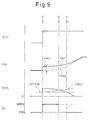
- the supply of the auxiliary fuel Qv is started as in the first embodiment of the present invention.
- the supercharge pressure shortage PMS gradually becomes smaller, and a turbo state representative value TRB, such as the actual supercharge pressure PMA, gradually becomes larger.
- a set value PMS1 corresponding to the set value OPS1 becomes larger when the turbo state representative value TRB becomes large, as shown in Fig. 10 .
- This set value PMS1 is stored in the ROM 32 in advance in the form of a map shown in Fig. 10 .
- the supply of the auxiliary fuel Qv is stopped or prohibited.
- a broken line I in Fig. 9 shows a case according to the first embodiment of the present invention.
- the supply of the auxiliary fuel Qv is continued until when the supercharge pressure shortage PMS is smaller than the permissible limit value LMTPM, as indicated by the arrow Y in Fig. 9 . Therefore, according to the second embodiment of the present invention, the supply of the auxiliary fuel Qv is stopped before the supercharge pressure shortage PMS is smaller than the permissible limit value LMTPM.
- the auxiliary fuel Qv can be used more effectively.
- the reason why the second embodiment of the present invention is operated in this way is as follows. Specifically, after the supply of the auxiliary fuel Qv is turned stopped, the actual supercharge pressure PMA and the turbine speed do not reduce immediately, due to the inertia of the turbocharger 5. Therefore, if the supply of the auxiliary fuel Qv is stopped after the output shortage representative value OPS is smaller than the permissible limit value LMT, an over-supercharge may occur, that is, the supercharge pressure or the turbine speed may exceed a respective permissible upper limit. Further, in this case, the auxiliary fuel Qv is supplied excessively, which may increase the fuel consumption rate or the exhaust emission.
- turbo state representative value TRB when the turbo state representative value TRB is small, over-supercharge or the like may occur if the output shortage representative value OPS is relatively small. In contrast, when the turbo state representative value TRB is large, over-supercharge may occur even if the output shortage representative value OPS is relatively large.
- the set value OPS1 that becomes larger when the turbo state representative value TRB becomes larger is set, and the supply of the auxiliary fuel Qv is stopped when the output shortage representative value OPS is smaller than the set value OPS1.
- auxiliary fuel Qv is reduced to zero in the above-mentioned second embodiment of the present invention.
- the output shortage representative value OPS is larger than the set value OPS1 when the output shortage representative value OPS exceeds the permissible limit value LMT (see an arrow X) and, therefore, the supply of the auxiliary fuel Qv is started.
- the output shortage representative value OPS is smaller than the set value OPS1 when the output shortage representative value OPS exceeds the permissible limit value LMT. In such a case, the supply of the auxiliary fuel Qv is not started.
- Fig. 11 is a flowchart of a supply control routine of the auxiliary fuel Qv according to the second embodiment of the present invention. This routine is executed by an interruption every predetermined time.
- step 110 the required output representative value OPT is calculated.
- step 111 the actual output representative value OPA is calculated.
- step 113 a supply and stop control routine of the auxiliary fuel Qv, which is shown in Fig. 12 , is executed.
- step 120 the set value OPS1 is calculated.
- a configuration of the third embodiment of the present invention is different from that of the second embodiment in that a change rate DOPA of the actual output representative value OPA, and a set value DOPA1 (>0) that is determined according to the turbo state representative value TRB, are obtained, and the supply of the auxiliary fuel Qv is stopped when the change rate DOPA of the actual output representative value is larger than the set value DOPA1.
- the third embodiment of the present invention will be explained below, taking a case where the engine output is represented by the supercharge pressure PM as an example.
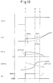
- the supply of the auxiliary fuel Qv is started as in the first embodiment.
- the change rate DPMA of the actual supercharge pressure gradually becomes larger.
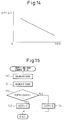
- the set value DPMA1 corresponding to the set value DOPA1 gradually becomes smaller when the turbo state representative value TRB becomes larger as shown in Fig. 14 .
- This set value DPMA1 is stored in the ROM 32 in advance in the form of a map as shown in Fig. 14 .
- the supply of the auxiliary fuel Qv is stopped before the supercharge pressure shortage PMS is smaller than the permissible limit value LMTPM. Therefore, the auxiliary fuel can be used more effectively.
- the turbo state representative value TRB when the turbo state representative value TRB is small, over-supercharge may occur if the change rate DOPA of the actual output representative value is relatively large, that is, the slope of the increase of the actual output representative value OPA is large.
- the turbo state representative value TRB when the turbo state representative value TRB is large, over-supercharge may occur even if the change rate DOPA of the actual output representative value is relatively small, that is, the slope of the actual output representative value OPA is slight. So, the set value DOPA1 that becomes smaller when the turbo state representative value TRB becomes larger is set, and the supply of the auxiliary fuel Qv is stopped when the change rate DOPA of the actual output representative value is larger than the set value DOPA1.
- Fig. 15 is a flowchart of a supply and stop control routine of the auxiliary fuel Qv according to the third embodiment of the present invention. This routine is executed in step 113 in Fig. 11 , for example.
- step 130 the change rate DOPA of the actual output representative value is calculated.
- step 131 the set value DOPA1 is calculated.
- a configuration of the fourth embodiment of the present invention is different from that of the second embodiment in that a change rate DOPS of the actual shortage OPS, and a set value DOPS1 ( ⁇ 0) that is determined according to the turbo-state representative value TRB, are obtained, and the supply of the auxiliary fuel Qv is stopped when the change rate DOPS of the output shortage representative value is smaller than the set value DOPS1.
- the fourth embodiment of the present invention will be explained below, taking again a case where the engine output is represented by the supercharge pressure PM as an example.
- the supply of the auxiliary fuel Qv is started as in the first embodiment.
- the change rate DPMS of the supercharge pressure shortage once increases and then becomes smaller from zero.
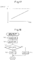
- the set value DPMS1 corresponding to the set value DOPS1 gradually becomes larger when the turbo state representative value TRB becomes larger as shown in Fig. 17 .
- This set value DPMS1 is stored in the ROM 32 in advance in the form of a map as shown in Fig. 17 .
- the turbo state representative value TRB When the turbo state representative value TRB is small, over-supercharge may occur if the change rate DOPS of the output shortage representative value is relatively small, that is, the slope of the decrease of the output shortage representative value OPS is large. On the other hand, when the turbo state representative value TRB is large, over-supercharge may occur even if the change rate DOPS of the output shortage representative value is relatively large, that is, the slope of the output shortage representative value OPS is slight. So, the set value DOPA1 that becomes larger when the turbo state representative value TRB becomes larger is set, and the supply of the auxiliary fuel Qv is stopped when the change rate DOPS of the output shortage representative value is smaller than the set value DOPS1.
- Fig. 18 is a flowchart of a supply and stop control routine of the auxiliary fuel Qv according to the fourth embodiment of the present invention. This routine is executed in step 113 in Fig. 11 , for example.
- step 140 the change rate DOPS of the output shortage representative value is calculated.
- step 141 the set value DOPS1 is calculated.
- Fig. 19 shows an alternative embodiment of the set value DOPS1.
- the set value DOPA1 becomes larger when the turbo state representative value TRB becomes larger, and becomes larger when the output shortage representative value OPS becomes smaller.
- the set value DOPS1 is set according to the turbo state representative value TRB and the output shortage representative value OPS, the supply of the auxiliary fuel Qv is stopped when the change rate DOPS of the output shortage representative value is smaller than the set value DOPS1.
- the set value DOPS1 in the fourth embodiment of the present invention described with reference to Fig. 17 is set according only to the turbo state representative value TRB regardless of the output shortage representative value OPS.
- the exhaust energy EEXON assuming that the auxiliary fuel Qv is supplied, is predicted, and the supply of the auxiliary fuel Qv is stopped when the predicted exhaust energy EEXON is larger than a preset amount EEX1.
- the configuration of the fifth embodiment is different from those of the second through fourth embodiments in this point.
- the fifth embodiment of the present invention will be explained below, taking a case where the exhaust energy is represented by the temperature TEX of the exhaust gas discharged from the combustion chamber and entering the exhaust turbine 5t as an example.
- the exhaust energy may be represented by, for example, the heat amount of the exhaust gas that flows into the exhaust turbine 5t.
- TEXOLD represents the temperature TEX of the exhaust gas after the previous combustion cycle has been completed.
- the temperature TEX of the exhaust gas after the next combustion cycle is completed will be TEXOFF.
- the temperature TEX of the exhaust gas after the next combustion cycle is completed will be TEXON assuming that the auxiliary fuel Qv is supplied in the next combustion cycle. This TEXON is higher than TEXOFF by an increment ⁇ TEX.
- the temperature TEXOFF of the exhaust gas assuming that the supply of the auxiliary fuel Qv is stopped in the next combustion cycle depends on the main fuel Qm (see Fig. 2 ), and can be predicted based on, for example, a temperature TEXOLD of the exhaust gas in the previous combustion cycle and an injection parameter of the main fuel Qm such as an injection amount or an injection timing.
- the increment ⁇ TEX depends on the auxiliary fuel Qv, and can be predicted based on an injection parameter of the auxiliary fuel Qv, such as an injection amount or an injection timing.
- exhaust energy EEXOFF assuming that the supply of the auxiliary fuel Qv is stopped in the next combustion cycle is predicted
- an increment ⁇ EEX of the exhaust energy by the auxiliary fuel Qv is predicted
- the exhaust energy EEXON assuming that the auxiliary fuel Qv is supplied in the next combustion cycle is predicted based on EEXOFF and ⁇ EEX
- the supply of the auxiliary fuel Qv is stopped in the next combustion cycle when the predicted exhaust energy EEXOFF is larger than the set amount EEX1.
- Fig. 21 is a flowchart of a supply and stop control routine of the auxiliary fuel Qv according to the fifth embodiment of the present invention. This routine is executed in step 113 in Fig. 11 , for example.
- step 150 the exhaust energy EEXON assuming that the auxiliary fuel Qv is supplied in the next combustion cycle is calculated.
- the exhaust emission amount that is, the amount of hydrocarbon, particulates, or smoke contained in the exhaust gas, increases in comparison with a case when the auxiliary fuel Qv is not supplied.
- the increase rate of the collected amount of particulates on the particulate filter 13 when the auxiliary fuel Qv is supplied is higher than that when the supply of the auxiliary fuel Qv is stopped.
- the additional fuel Qa (see Fig. 2 ) is supplied each time when the collected amount of particulates on the particulate filter 13 reaches a set amount which may be constant. Accordingly, the frequency of the supply of the additional fuel Qa when the auxiliary fuel Qv is supplied is higher than that when the supply of the auxiliary fuel Qv is stopped. Therefore, the fuel consumption rate may increase further.
- the exhaust emission amount QEMON assuming that the auxiliary fuel Qv is supplied is predicted, and the supply of the auxiliary fuel Qv is stopped when the predicted exhaust emission amount QEMON is larger than the preset amount QEM1.
- the configuration of the sixth embodiment is different from those of the second to the fifth embodiments in this point.
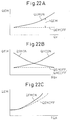
- the exhaust emission amount QEM depends on the injection parameter of the auxiliary fuel Qv and the atmosphere in the cylinder to which the auxiliary fuel Qv is supplied. Specifically, as shown in Fig. 22A , the exhaust emission amount QEMON when the auxiliary fuel Qv is supplied increases when the auxiliary fuel amount Qv increases, and an increment ⁇ QEM of the exhaust emission amount QEMON with respect to the exhaust emission amount QEMOFF when the supply of the auxiliary fuel Qv is stopped also increases when the auxiliary fuel amount Qv increases. Also, as shown in Fig.
- a smoke amount QSMON when the auxiliary fuel Qv is supplied increases when an injection timing ⁇ Qv of the auxiliary fuel Qv is retarded, and an increment of the smoke amount QSMON with respect to the smoke amount QSMOFF when the supply of the auxiliary fuel Qv is stopped also increases when the injection timing ⁇ Qv is retarded.
- a hydrocarbon amount QHCON when the auxiliary fuel Qv is supplied increases when the injection timing ⁇ Qv of the auxiliary fuel Qv is advanced, and an increment of the hydrocarbon amount QHCON with respect to a hydrocarbon amount QHCOFF when the supply of the auxiliary fuel Qv is stopped also increases when the injection timing ⁇ Qv is advanced.
- the exhaust emission amount QEMON when the auxiliary fuel Qv is supplied increases when the actual torque TQA increases, and an increment of the exhaust emission amount QEMON with respect to the exhaust emission amount QEMOFF when the supply of the auxiliary fuel Qv is stopped also increases when the actual torque TQA increases.
- the actual torque depends on the main fuel Qm, and represents the atmosphere in the cylinder at the timing of the supply of the auxiliary fuel Qv.
- Fig. 22A the injection timing ⁇ Qv of the auxiliary fuel Qv and the actual torque TQA are maintained at constant levels.
- Fig. 22B the auxiliary fuel amount Qv and the actual torque TQA are maintained at constant levels.
- Fig. 22C the auxiliary fuel amount Qv and the injection timing ⁇ Qv of the auxiliary fuel Qv are maintained at constant levels.
- the exhaust emission amount QEMOFF assuming that the supply of the auxiliary fuel Qv is stopped in the next combustion cycle, depends on the main fuel Qm, and can be predicted based on the engine speed, the actual torque, the EGR ratio, the intake air amount, the intake air temperature, or the like.
- the increment ⁇ QEM depends on the auxiliary fuel Qv, and can be predicted based on the injection parameter of the auxiliary fuel Qv such as the auxiliary fuel amount Qv and the injection timing ⁇ Qv.
- the exhaust emission amount QEMOFF assuming that the supply of the auxiliary fuel Qv is stopped in the next combustion cycle
- the increment ⁇ QEM are predicted
- the exhaust emission amount QEMON assuming that the auxiliary fuel Qv is supplied in the next combustion cycle
- the supply of the auxiliary fuel Qv is stopped in the next combustion cycle.
- the auxiliary fuel Qv is supplied in the next combustion cycle. In this case, when at least one of the amounts of hydrocarbon, particulates, and smoke is larger than the corresponding set amounts, the supply of the auxiliary fuel Qv may be stopped.
- the set amount QEM1 may be set constant, the set amount QEM1 is set depending on the engine operation state according to the sixth embodiment of the present invention. For example, the set amount QEM1 is set based on the engine speed, the actual torque TQA, and the intake air amount.
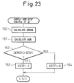
- Fig. 23 is a flowchart of a supply and stop control routine of the auxiliary fuel Qv according to the sixth embodiment of the present invention. This routine is executed in step 113 in Fig. 11 , for example.
- step 160 the exhaust emission amount QEMON assuming that the auxiliary fuel Qv is supplied in the next combustion cycle is calculated.
- the set amount QEM1 is calculated.
- QEMON represents the exhaust emission amount per combustion cycle assuming that the auxiliary fuel Qv is supplied. Therefore, QEMON can be considered to represent the increase or change rate of the exhaust emission amount assuming that the auxiliary fuel Qv is supplied. Accordingly, in the sixth embodiment, the supply of the auxiliary fuel Qv is stopped when the change rate of the exhaust emission amount, assuming that the auxiliary fuel Qv is supplied, is larger than the set value.
- QDPFON represents a collected amount of particulates on the particulate filter 13, assuming that the auxiliary fuel Qv is supplied
- QDPFOFF represents a collected amount of particulates on the particulate filter 13, assuming that the supply of the auxiliary fuel Qv is stopped
- the collected particulates amount QDPFON assuming that the auxiliary fuel Qv is supplied
- the collected particulates amount QDPFOFF assuming that the supply of the auxiliary fuel Qv is stopped, both increase along lapse of time.
- the increment ⁇ QDPF also increases along lapse of time.
- the supply of the auxiliary fuel Qv is stopped when the increase or change rate QDPFON of the collected amount of particulates assuming that the auxiliary fuel Qv is supplied is large, and is permitted when the increase rate QDPFON of the collected amount of particulates is small.
- the supply of the auxiliary fuel Qv should be stopped.
- the increment ⁇ QDPF represents the influence of the auxiliary fuel Qv on the collected amount of particulates QDPFON. Therefore, when the increase or change rate of the increment ⁇ QDPF is large, it can be said that the increase rate of the collected amount of particulates QDPFON becomes large due to the auxiliary fuel Qv.
- the configuration of the seventh embodiment is different from that of the sixth embodiment in this point.
- the set value D ⁇ 1 can be set constant
- the set amount QEM1 is set depending on the engine operation state according to the seventh embodiment of the present invention. Specifically, the set amount QEM1 is set based on the engine speed, the actual torque TQA and the intake air amount, for example.
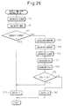
- Fig. 25 is a flowchart of a supply and stop control routine of the auxiliary fuel Qv according to the seventh embodiment of the present invention. This routine is executed in step 113 in Fig. 11 , for example.
- step 170 the exhaust emission amount QEMON assuming that the auxiliary fuel Qv is supplied in the next combustion cycle is calculated.
- the set amount QEM1 is calculated.
- step 174 a collected amount of particulates QQDPFON when the vehicle runs through a reference period such as a constant time or distance, assuming that the auxiliary fuel Qv is supplied, is calculated.
- step 175 the collected amount of particulates QQDPFOFF when the vehicle runs through the reference period assuming that the supply of the auxiliary fuel Qv is stopped, is calculated. Note that in the case where the exhaust emission amount QEMON calculated in step 170 and the exhaust emission amount QEMOFF are the amounts of particulates, the collected particulates amounts QQDPFON and QQDPFOFF are obtained by accumulating QEMON and QEMOFF, respectively, through the reference period.
- the change rate D ⁇ of the increment is calculated.
- the set value D ⁇ 1 is calculated.
- the seventh embodiment it is judged whether the supply of the auxiliary fuel Qv is to be stopped based on the change rate D ⁇ of the increment, when the exhaust emission amount QEM is smaller than the set amount QEM1.
- the judgment whether the supply of the auxiliary fuel Qv is to be stopped based on the change rate D ⁇ of the increment may be executed regardless of the exhaust emission amount QEM.
- the temperature of the particulate filter 13 also rises. In this case, if a relatively large amount of particulates are collected on the particulate filter 13, the large amount of particulates may be abnormally combusted which may lead melting of the particulate filter 13.
- the eighth embodiment of the present invention when the collected amount of particulates QDPF on the particulate filter 13 is larger than the preset amount QDPF1, the supply of the auxiliary fuel Qv is stopped.
- the configuration of the eighth embodiment is different from those of the second to the fifth embodiments in this point.
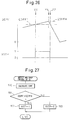
- the temperature increase control is started and, thereby, the collected amount of particulates QDPF is gradually reduced.
- Fig. 27 is a flowchart of a supply and stop control routine of the auxiliary fuel Qv according to the eighth embodiment of the present invention. This routine is executed in step 113 in Fig. 11 , for example.
- step 190 the collected amount of particulates QDPF on the particulate filter 13 is calculated.
- the auxiliary fuel can be used effectively to increase the exhaust energy.
Landscapes
- Engineering & Computer Science (AREA)
- Chemical & Material Sciences (AREA)
- Combustion & Propulsion (AREA)
- Mechanical Engineering (AREA)
- General Engineering & Computer Science (AREA)
- Output Control And Ontrol Of Special Type Engine (AREA)
- Electrical Control Of Air Or Fuel Supplied To Internal-Combustion Engine (AREA)
- Supercharger (AREA)
- Processes For Solid Components From Exhaust (AREA)
- Combined Controls Of Internal Combustion Engines (AREA)
Claims (9)
- Kraftstoffzuführsteuerungsvorrichtung für eine Brennkraftmaschine mit einem Abgaslader, die Kraftstoffzuführsteuerungsvorrichtung mit:einem Kraftstoffeinspritzventil, das einen Kraftstoff direkt in einen Zylinder einspritzt;einer Beurteilungseinrichtung, zum Beurteilen, ob ein Mangel einer tatsächlichen Maschinenleistung verglichen mit einer geforderten Leistung größer ist als ein vorbestimmter zulässiger Grenzwert; undeiner Erhöhungseinrichtung, zum Zuführen von Zusatzkraftstoff aus dem Kraftstoffeinspritzventil bei einem Arbeitshub, nachdem ein Hauptkraftstoff zugeführt wurde, um eine Abgasenergie zeitweise zu erhöhen, die eine Energie eines in den Abgaslader strömenden Abgases ist, wenn die Beurteilungseinrichtung beurteilt, dass der Leistungsmangel größer ist als der zulässige Grenzwert,die Kraftstoffzuführsteuerungsvorrichtung ferner mit:einer Unterdrückungseinrichtung, zum Beurteilen, ob eine Erhöhung der Abgasenergie unter Verwendung des Zusatzkraftstoffs unterdrückt werden soll und zum Verringern einer Zuführmenge des Zusatzkraftstoffs, wenn beurteilt wird, dass die Erhöhung der Abgasenergie unter Verwendung des Zusatzkraftstoffs unterdrückt werden soll,wobei die Unterdrückungseinrichtung eine Abgasemissionsmengenvorhersageeinrichtung, zum Vorhersagen einer Abgasemissionsmenge, unter der Annahme, dass der Zusatzkraftstoff zugeführt wird, aufweist, und wobei die Unterdrückungseinrichtung beurteilt, dass die Erhöhung der Abgasenergie unter Verwendung des Zusatzkraftstoffs unterdrückt werden soll, wenn die vorhergesagte Abgasemissionsmenge größer ist als eine im Voraus bestimmte festgelegte Abgasemissionsmenge, und dadurch gekennzeichnet, dassein Partikelfilter, zum Sammeln von in dem Abgas enthaltenen Partikeln in einem Abgaspfad der Brennkraftmaschine angeordnet ist, wobei die Unterdrückungseinrichtung eine Einrichtung zum Erlangen einer Zunahme der gesammelten Menge an Partikeln auf dem Partikelfilter unter der Annahme, dass die Zufuhr des Zusatzkraftstoffs angehalten ist und weiter zum Erlangen einer Änderungsgeschwindigkeit der Zunahme aufweist, wenn die vorhergesagte Abgasemissionsmenge kleiner ist als die festgelegte Abgasemissionsmenge, und wobei die Unterdrückungseinrichtung beurteilt, dass die Zunahme der Abgasenergie unter Verwendung des Zusatzkraftstoffs unterdrückt werden soll, wenn die erlangte Änderungsgeschwindigkeit der Zunahme größer als eine im Voraus bestimmte festgelegte Änderungsgeschwindigkeit ist.
- Kraftstoffzuführsteuerungsvorrichtung für eine Brennkraftmaschine mit einem Abgaslader, die Kraftstoffzuführsteuerungsvorrichtung mit:einem Kraftstoffeinspritzventil, das einen Kraftstoff direkt in einen Zylinder einspritzt;einer Beurteilungseinrichtung, zum Beurteilen, ob ein Mangel einer tatsächlichen Maschinenleistung verglichen mit einer geforderten Leistung größer ist als ein vorbestimmter zulässiger Grenzwert; undeiner Erhöhungseinrichtung, zum Zuführen von Zusatzkraftstoff aus dem Kraftstoffeinspritzventil bei einem Arbeitshub, nachdem ein Hauptkraftstoff zugeführt wurde, um eine Abgasenergie zeitweise zu erhöhen, die eine Energie eines in den Abgaslader strömenden Abgases ist, wenn die Beurteilungseinrichtung beurteilt, dass der Leistungsmangel größer ist als der zulässige Grenzwert,die Kraftstoffzuführsteuerungsvorrichtung ferner mit:einer Unterdrückungseinrichtung, zum Beurteilen, ob eine Erhöhung der Abgasenergie unter Verwendung des Zusatzkraftstoffs unterdrückt werden soll und zum Verringern einer Zuführmenge des Zusatzkraftstoffs, wenn beurteilt wird, dass die Erhöhung der Abgasenergie unter Verwendung des Zusatzkraftstoffs unterdrückt werden soll, dadurch gekennzeichnet, dassein Partikelfilter, zum Sammeln von in dem Abgas enthaltenen Partikeln in dem Abgaspfad der Brennkraftmaschine angeordnet ist, wobei die Unterdrückungseinrichtung eine Einrichtung zum Erlangen einer Zunahme der auf dem Partikelfilter gesammelten Menge an Partikeln, unter der Annahme, dass die Zufuhr des Zusatzkraftstoffs zugeführt wird, bezüglich dessen unter der Annahme, dass die Zufuhr des Zusatzkraftstoffs angehalten ist, und ebenfalls zum Erlangen einer Änderungsgeschwindigkeit der Zunahme aufweist, und wobei die Unterdrückungseinrichtung beurteilt, dass die Erhöhung der Abgasenergie unter Verwendung des Zusatzkraftstoffs unterdrückt werden soll, wenn die erlangte Änderungsgeschwindigkeit der Zunahme größer als eine im Voraus bestimmte festgelegte Geschwindigkeit ist.
- Kraftstoffzuführsteuerungsvorrichtung für eine Brennkraftmaschine nach Anspruch 2, wobei die festgelegte Geschwindigkeit in Abhängigkeit eines Maschinenbetriebszustands festgelegt wird.
- Kraftstoffzuführsteuerungsvorrichtung für eine Brennkraftmaschine mit einem Abgaslader, die Kraftstoffzuführsteuerungsvorrichtung mit:einem Kraftstoffeinspritzventil, das einen Kraftstoff direkt in einen Zylinder einspritzt;einer Beurteilungseinrichtung, zum Beurteilen, ob ein Mangel einer tatsächlichen Maschinenleistung verglichen mit einer geforderten Leistung größer ist als ein vorbestimmter zulässiger Grenzwert; undeiner Erhöhungseinrichtung, zum Zuführen von Zusatzkraftstoff aus dem Kraftstoffeinspritzventil bei einem Arbeitshub, nachdem ein Hauptkraftstoff zugeführt wurde, um eine Abgasenergie zeitweise zu erhöhen, die eine Energie eines in den Abgaslader strömenden Abgases ist, wenn die Beurteilungseinrichtung beurteilt, dass der Leistungsmangel größer ist als der zulässige Grenzwert,die Kraftstoffzuführsteuerungsvorrichtung ferner mit:einer Unterdrückungseinrichtung, zum Beurteilen, ob eine Erhöhung der Abgasenergie unter Verwendung des Zusatzkraftstoffs unterdrückt werden soll und zum Verringern einer Zuführmenge des Zusatzkraftstoffs, wenn beurteilt wird, dass die Erhöhung der Abgasenergie unter Verwendung des Zusatzkraftstoffs unterdrückt werden soll, dadurch gekennzeichnet, dassein Partikelfilter, zum Sammeln von in dem Abgas enthaltenen Partikeln in dem Abgaspfad der Brennkraftmaschine angeordnet ist, wobei die Unterdrückungseinrichtung eine Einrichtung zum Erlangen der gesammelten Menge von Partikeln auf dem Partikelfilter aufweist, und wobei die Unterdrückungseinrichtung beurteilt, dass die Zunahme der Abgasenergie unter Verwendung des Zusatzkraftstoffs unterdrückt werden soll, wenn die gesammelte Partikelmenge größer ist als ein im Voraus bestimmter festgelegter Partikelwert oder diesen übersteigt.
- Kraftstoffzuführsteuerungsvorrichtung für eine Brennkraftmaschine nach einem der Ansprüche 1 bis 4, wobei wenn die Unterdrückungseinrichtung beurteilt, dass die Erhöhung der Abgasenergie unter Verwendung des Zusatzkraftstoffs unterdrückt werden soll, die Unterdrückungseinrichtung die Zufuhr des Zusatzkraftstoffs unabhängig davon anhält, ob der Leistungsmangel größer ist als der zulässige Grenzwert.
- Kraftstoffzuführsteuerungsvorrichtung für eine Brennkraftmaschine nach einem der Ansprüche 1 bis 4, wobei die Erhöhungseinrichtung die Erhöhung der Abgasenergie unter Verwendung des Zusatzkraftstoffs anhält, wenn beurteilt wird, dass der Leistungsmangel kleiner ist als der zulässige Grenzwert.
- Kraftstoffzuführsteuerungsvorrichtung für eine Brennkraftmaschine nach einem der Ansprüche 1 bis 4, wobei die Beurteilungseinrichtung einen repräsentativen Wert einer erforderlichen Leistung, der die erforderliche Leistung repräsentiert, beziehungsweise einen repräsentativen Wert einer tatsächlichen Leistung erlangt, der die tatsächliche Maschinenleistung repräsentiert, sowie einen repräsentativen Wert eines Leistungsmangels erlangt, der den Leistungsmangel repräsentiert, indem sie den repräsentativen Wert der tatsächlichen Leistung von dem repräsentativen Wert der erforderlichen Leistung subtrahiert, und wobei die Beurteilungseinrichtung beurteilt, dass der Leistungsmangel größer ist als der zulässige Grenzwert, wenn der repräsentative Wert des Leistungsmangels größer ist als ein im Voraus bestimmter festgelegter Wert.
- Kraftstoffzuführsteuerungsvorrichtung für eine Brennkraftmaschine nach einem der Ansprüche 1 bis 4, wobei sowohl die erforderliche Leistung als auch die tatsächliche Maschinenleistung durch das erforderliche und tatsächliche Drehmoment repräsentiert wird, das auf der Basis eines Niederdrückens eines Gaspedals erlangt wird, und/oder den erforderlichen und tatsächlichen Ladedruck, der auf der Basis eines Niederdrückens eines Gaspedals erlangt wird.
- Kraftstoffzuführsteuerungsvorrichtung für eine Brennkraftmaschine nach einem der Ansprüche 1 bis 4, wobei die Brennkraftmaschine eine Selbstzünderbrennkraftmaschine ist.
Applications Claiming Priority (2)
| Application Number | Priority Date | Filing Date | Title |
|---|---|---|---|
| JP2004197972A JP4007346B2 (ja) | 2004-07-05 | 2004-07-05 | 内燃機関の燃料供給制御装置 |
| PCT/JP2005/012723 WO2006004218A1 (ja) | 2004-07-05 | 2005-07-05 | 内燃機関の燃料供給制御装置 |
Publications (3)
| Publication Number | Publication Date |
|---|---|
| EP1764497A1 EP1764497A1 (de) | 2007-03-21 |
| EP1764497A4 EP1764497A4 (de) | 2014-08-27 |
| EP1764497B1 true EP1764497B1 (de) | 2016-10-19 |
Family
ID=35783012
Family Applications (1)
| Application Number | Title | Priority Date | Filing Date |
|---|---|---|---|
| EP05758021.9A Expired - Lifetime EP1764497B1 (de) | 2004-07-05 | 2005-07-05 | Kraftstoffversorgungssteuervorrichtung für verbrennungsmotor |
Country Status (4)
| Country | Link |
|---|---|
| EP (1) | EP1764497B1 (de) |
| JP (1) | JP4007346B2 (de) |
| CN (1) | CN100427744C (de) |
| WO (1) | WO2006004218A1 (de) |
Families Citing this family (4)
| Publication number | Priority date | Publication date | Assignee | Title |
|---|---|---|---|---|
| JP5301857B2 (ja) * | 2008-03-03 | 2013-09-25 | ヤンマー株式会社 | コモンレール式電子噴射制御系エンジン |
| CN102182573B (zh) * | 2011-03-21 | 2013-05-29 | 中国北车集团大连机车车辆有限公司 | 内燃机车电喷柴油机载荷控制方法 |
| US9970424B2 (en) * | 2012-03-13 | 2018-05-15 | General Electric Company | System and method having control for solids pump |
| US9745914B2 (en) * | 2014-10-27 | 2017-08-29 | Toyota Jidosha Kabushiki Kaisha | Control apparatus for internal combustion engine |
Family Cites Families (6)
| Publication number | Priority date | Publication date | Assignee | Title |
|---|---|---|---|---|
| JP3238257B2 (ja) * | 1993-10-05 | 2001-12-10 | 株式会社デンソー | 蓄圧式燃料噴射装置 |
| DE19525667A1 (de) * | 1995-07-14 | 1997-01-16 | Audi Ag | Vorrichtung an einer Brennkraftmaschine mit einem Abgasturbolader |
| JP2002364413A (ja) * | 2001-06-07 | 2002-12-18 | Mazda Motor Corp | ターボ過給機付き筒内噴射式エンジンの排気浄化装置 |
| JP4042399B2 (ja) * | 2001-12-12 | 2008-02-06 | 三菱自動車工業株式会社 | 排気浄化装置 |
| JP4161575B2 (ja) * | 2002-01-16 | 2008-10-08 | 三菱ふそうトラック・バス株式会社 | 内燃機関の排気浄化装置 |
| FR2840649B1 (fr) * | 2002-06-06 | 2005-05-20 | Renault Sa | Procede d'augmentation de performances d'un moteur suralimente |
-
2004
- 2004-07-05 JP JP2004197972A patent/JP4007346B2/ja not_active Expired - Fee Related
-
2005
- 2005-07-05 WO PCT/JP2005/012723 patent/WO2006004218A1/ja not_active Ceased
- 2005-07-05 EP EP05758021.9A patent/EP1764497B1/de not_active Expired - Lifetime
- 2005-07-05 CN CNB2005800012101A patent/CN100427744C/zh not_active Expired - Fee Related
Also Published As
| Publication number | Publication date |
|---|---|
| JP2006017070A (ja) | 2006-01-19 |
| EP1764497A1 (de) | 2007-03-21 |
| EP1764497A4 (de) | 2014-08-27 |
| JP4007346B2 (ja) | 2007-11-14 |
| WO2006004218A1 (ja) | 2006-01-12 |
| CN100427744C (zh) | 2008-10-22 |
| CN1878942A (zh) | 2006-12-13 |
Similar Documents
| Publication | Publication Date | Title |
|---|---|---|
| JP3972611B2 (ja) | 内燃機関の排気浄化装置 | |
| JP4161690B2 (ja) | 蓄圧式燃料噴射装置 | |
| CN102124200B (zh) | 内燃机的控制装置 | |
| EP2787206B1 (de) | Brennstoffeinspritzsystem für verbrennungsmotoren | |
| CN100340757C (zh) | 内燃机的燃油喷射控制系统 | |
| US9546629B2 (en) | Control device of diesel engine with turbocharger | |
| JP5067509B2 (ja) | 多気筒内燃機関の気筒間空燃比ばらつき異常検出装置 | |
| US20090158713A1 (en) | Exhaust Gas Purification System for Internal Combustion Engine | |
| EP1983179B1 (de) | Motorsteuerverfahren und motorsteuersystem | |
| US8984865B2 (en) | Exhaust gas purification device for internal combustion engine | |
| EP1867857B1 (de) | System zur Steuerung der Kraftstoffeinspritzung für einen Verbrennungsmotor | |
| US20030131833A1 (en) | System and method for detecting an air leak in an engine | |
| EP1764497A1 (de) | Kraftstoffversorgungssteuervorrichtung für verbrennungsmotor | |
| JP6202063B2 (ja) | 内燃機関の制御装置 | |
| EP1662123B1 (de) | Vorrichtung zur Erhöhung der Temperatur eines Katalysators für Brennkraftmaschine | |
| EP1493483B1 (de) | Abgasreinigungsanlage einer Brennkraftmaschine | |
| US11408360B2 (en) | Engine device | |
| EP2290210B1 (de) | System zur Steuerung der Kraftstoffzufuhr für einen Verbrennungsmotor | |
| JP2010071125A (ja) | 直接噴射式内燃機関の燃料噴射制御装置 | |
| JP2008075565A (ja) | 内燃機関の制御装置 | |
| JP4178988B2 (ja) | 圧縮着火内燃機関の始動制御装置 | |
| JP2019135382A (ja) | 内燃機関の制御装置 | |
| US11319885B2 (en) | Control method and control device for vehicular internal combustion engine | |
| JP4140387B2 (ja) | 内燃機関の排気浄化装置 | |
| JP2017002805A (ja) | 車両の暖機制御装置 |
Legal Events
| Date | Code | Title | Description |
|---|---|---|---|
| PUAI | Public reference made under article 153(3) epc to a published international application that has entered the european phase |
Free format text: ORIGINAL CODE: 0009012 |
|
| 17P | Request for examination filed |
Effective date: 20060327 |
|
| AK | Designated contracting states |
Kind code of ref document: A1 Designated state(s): DE FR IT |
|
| DAX | Request for extension of the european patent (deleted) | ||
| RBV | Designated contracting states (corrected) |
Designated state(s): DE FR IT |
|
| RAP1 | Party data changed (applicant data changed or rights of an application transferred) |
Owner name: TOYOTA JIDOSHA KABUSHIKI KAISHA |
|
| RIC1 | Information provided on ipc code assigned before grant |
Ipc: F02B 37/00 20060101ALI20140716BHEP Ipc: F02D 41/40 20060101ALI20140716BHEP Ipc: F02D 23/00 20060101ALI20140716BHEP Ipc: F01N 3/02 20060101ALI20140716BHEP Ipc: F02D 41/02 20060101ALI20140716BHEP Ipc: F02D 41/38 20060101AFI20140716BHEP Ipc: F02D 45/00 20060101ALI20140716BHEP Ipc: F02D 41/00 20060101ALI20140716BHEP |
|
| A4 | Supplementary search report drawn up and despatched |
Effective date: 20140729 |
|
| RIC1 | Information provided on ipc code assigned before grant |
Ipc: F02D 23/00 20060101ALI20140723BHEP Ipc: F02D 45/00 20060101ALI20140723BHEP Ipc: F02D 41/00 20060101ALI20140723BHEP Ipc: F02D 41/02 20060101ALI20140723BHEP Ipc: F01N 3/02 20060101ALI20140723BHEP Ipc: F02B 37/00 20060101ALI20140723BHEP Ipc: F02D 41/38 20060101AFI20140723BHEP Ipc: F02D 41/40 20060101ALI20140723BHEP |
|
| GRAP | Despatch of communication of intention to grant a patent |
Free format text: ORIGINAL CODE: EPIDOSNIGR1 |
|
| INTG | Intention to grant announced |
Effective date: 20160519 |
|
| GRAS | Grant fee paid |
Free format text: ORIGINAL CODE: EPIDOSNIGR3 |
|
| GRAA | (expected) grant |
Free format text: ORIGINAL CODE: 0009210 |
|
| AK | Designated contracting states |
Kind code of ref document: B1 Designated state(s): DE FR IT |
|
| REG | Reference to a national code |
Ref country code: DE Ref legal event code: R096 Ref document number: 602005050474 Country of ref document: DE |
|
| REG | Reference to a national code |
Ref country code: DE Ref legal event code: R084 Ref document number: 602005050474 Country of ref document: DE |
|
| REG | Reference to a national code |
Ref country code: DE Ref legal event code: R097 Ref document number: 602005050474 Country of ref document: DE |
|
| PLBE | No opposition filed within time limit |
Free format text: ORIGINAL CODE: 0009261 |
|
| STAA | Information on the status of an ep patent application or granted ep patent |
Free format text: STATUS: NO OPPOSITION FILED WITHIN TIME LIMIT |
|
| PG25 | Lapsed in a contracting state [announced via postgrant information from national office to epo] |
Ref country code: IT Free format text: LAPSE BECAUSE OF FAILURE TO SUBMIT A TRANSLATION OF THE DESCRIPTION OR TO PAY THE FEE WITHIN THE PRESCRIBED TIME-LIMIT Effective date: 20161019 |
|
| 26N | No opposition filed |
Effective date: 20170720 |
|
| PGFP | Annual fee paid to national office [announced via postgrant information from national office to epo] |
Ref country code: DE Payment date: 20170627 Year of fee payment: 13 |
|
| REG | Reference to a national code |
Ref country code: FR Ref legal event code: ST Effective date: 20180330 |
|
| PG25 | Lapsed in a contracting state [announced via postgrant information from national office to epo] |
Ref country code: FR Free format text: LAPSE BECAUSE OF NON-PAYMENT OF DUE FEES Effective date: 20170731 |
|
| REG | Reference to a national code |
Ref country code: DE Ref legal event code: R119 Ref document number: 602005050474 Country of ref document: DE |
|
| PG25 | Lapsed in a contracting state [announced via postgrant information from national office to epo] |
Ref country code: DE Free format text: LAPSE BECAUSE OF NON-PAYMENT OF DUE FEES Effective date: 20190201 |