EP1764498A2 - Konvergente-divergente Düse mit ineinander greifenden divergenten Klappen - Google Patents
Konvergente-divergente Düse mit ineinander greifenden divergenten Klappen Download PDFInfo
- Publication number
- EP1764498A2 EP1764498A2 EP06253792A EP06253792A EP1764498A2 EP 1764498 A2 EP1764498 A2 EP 1764498A2 EP 06253792 A EP06253792 A EP 06253792A EP 06253792 A EP06253792 A EP 06253792A EP 1764498 A2 EP1764498 A2 EP 1764498A2
- Authority
- EP
- European Patent Office
- Prior art keywords
- divergent
- flap
- nozzle
- extension
- longitudinal side
- Prior art date
- Legal status (The legal status is an assumption and is not a legal conclusion. Google has not performed a legal analysis and makes no representation as to the accuracy of the status listed.)
- Granted
Links
- 239000007789 gas Substances 0.000 description 9
- 238000001816 cooling Methods 0.000 description 8
- 230000007423 decrease Effects 0.000 description 6
- 239000000446 fuel Substances 0.000 description 4
- 230000008901 benefit Effects 0.000 description 3
- 239000000567 combustion gas Substances 0.000 description 2
- 230000010339 dilation Effects 0.000 description 2
- 230000004048 modification Effects 0.000 description 2
- 238000012986 modification Methods 0.000 description 2
- 238000011144 upstream manufacturing Methods 0.000 description 2
- 230000003190 augmentative effect Effects 0.000 description 1
- 230000000295 complement effect Effects 0.000 description 1
- 230000003247 decreasing effect Effects 0.000 description 1
- 239000007787 solid Substances 0.000 description 1
- 230000003068 static effect Effects 0.000 description 1
- 230000001360 synchronised effect Effects 0.000 description 1
Images


Classifications
-
- F—MECHANICAL ENGINEERING; LIGHTING; HEATING; WEAPONS; BLASTING
- F02—COMBUSTION ENGINES; HOT-GAS OR COMBUSTION-PRODUCT ENGINE PLANTS
- F02K—JET-PROPULSION PLANTS
- F02K1/00—Plants characterised by the form or arrangement of the jet pipe or nozzle; Jet pipes or nozzles peculiar thereto
- F02K1/06—Varying effective area of jet pipe or nozzle
- F02K1/12—Varying effective area of jet pipe or nozzle by means of pivoted flaps
- F02K1/1223—Varying effective area of jet pipe or nozzle by means of pivoted flaps of two series of flaps, the upstream series having its flaps hinged at their upstream ends on a fixed structure and the downstream series having its flaps hinged at their upstream ends on the downstream ends of the flaps of the upstream series
Definitions
- the present invention relates to gas turbine engines having convergent/divergent nozzles, and more particularly to a nozzle which provides an increased area ratio range (exit area/jet area).
- a variable area exhaust nozzle optimizes the thrust produced within a gas turbine engine.
- convergent/divergent (C/D) nozzles provide a multitude of nozzle positions.
- the term "convergent-divergent” describes an exhaust nozzle having a convergent section upstream of a divergent section. Exhaust gases exiting the turbine(s) pass through the decreasing diameter convergent section before passing through the increasing diameter divergent section.
- the convergent section is pivotally connected to the exhaust duct and to the divergent section.
- the divergent section is pivotally connected to the convergent section and to an external fairing positioned radially outboard of the divergent section.
- the opposite end of the external fairing is pivotally attached to a static outer case which surrounds a portion of the nozzle.
- variable orifice of the C/D nozzle is typically disposed at an interface between the aft end of the convergent section and the forward end of the divergent section. Orifice area increases and decreases when the aft end of the convergent section is displaced radially outward and inward, respectively.
- the nozzle defines a throat or jet area and an exit area.
- the jet area is the area at which the minimum cross sectional area of the nozzle is defined.
- the exit area is the aft most section of the nozzle.
- the area ratio of a nozzle is the exit area divided by the jet area.
- the area ratio range provides a general indicator of engine performance and an increase in the area ratio range results in more efficient engine performance with increased engine thrust, fuel efficiency and a decrease in actuator loads required to articulate the nozzle.
- the convergent and divergent sections generally include flaps and flap seals circumferentially disposed, attached to one of the other sections or to a structural member within the engine.
- the alternately disposed flaps and flap seals accommodate changes in orifice area and nozzle axis skew (if the nozzle is vectorable) by sliding relative to and overlapping each other as the orifice area decreases or increases.
- the nozzle system according to the present invention includes a plurality of circumferentially distributed convergent flaps, divergent flaps and divergent flap seals which circumscribe an engine centerline and define the radial outer boundary of a core gas path.
- Each divergent flap may be described as having a length defined as extending between a forward end and an aft end and a width defined between a first longitudinal side and a second longitudinal side.
- the forward end of each divergent flap includes a joint structure that forms a portion of a joint along a hinge axis that circumscribes the nozzle centerline.
- Each longitudinal side of each divergent flap includes a set of extensions which are located at different axial stations such that the extensions on adjacent divergent flaps interfit when the nozzle is in a minimum dilated position yet provide support for the intermediate flap seal when the nozzle is in a maximum dilated position to increase the area ratio range.
- the present invention therefore provides provide a C/D exhaust nozzle with an increased high-mode area ratio schedule without compromising the low-mode area ratio schedule.
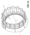
- Figures 1A and 1B illustrate a nozzle system 10 for a gas turbine engine.
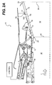
- Figure 1A depicts the nozzle 10 in a maximum dilated position (also illustrated in Figure 2A), which is typically used during afterburning operation
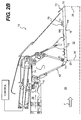
- Figure 1B depicts the nozzle system 10 in a minimal dilated position (Figure 2B), which is typically used during non-afterburning operation.
- the nozzle includes a plurality of circumferentially distributed convergent flaps 12 (only one shown in section), each pivotably connected to a stationary frame 14 with a cooling liner panel 16 upstream thereof.
- a plurality of circumferentially distributed divergent flaps 18 (only one shown in section) are pivotably connected at a joint 20 to an aft end section of the convergent flaps 12.
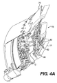
- a plurality of divergent flap seals 21 ( Figures 4A and 4B) are distributed circumferentially between the divergent flaps 18.
- the convergent and divergent flaps 12, 18 and the inter-flap seals 21 circumscribe the nozzle centerline A to define the radial outer boundary of an exhaust gas path 26.
- a control system governs the angular orientations of the convergent flaps 12 and divergent flaps 18 to adjust the nozzle throat area 34 and exit area 26 about a nozzle centerline A.
- the passageway 28 guides a cooling airflow (illustrated schematically be arrows C) along a radial inner surface of the convergent flaps 12.
- the cooling airflow C is typically sourced from fan bypass airflow and/or other airflow that is different from a combustion gas flow (illustrated schematically by arrow F).
- the cooling airflow C at least partially shields the flaps from the intense heat of the core combustion gas airflow F.
- the flaps 12, 18 define convergent and divergent sections 30, 32 of the nozzle with the throat 34 or jet area defined therebetween.
- the throat 34 is the minimum cross sectional area of the nozzle and when compared to the nozzle exit area 26 defines a nozzle area ratio.
- An increased area ratio range (Exit area/jet area) results in more efficient engine performance with increased engine thrust, fuel efficiency, with a significant decrease in actuator loads required to articulate the nozzle between the open and closed positions.
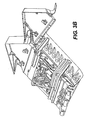
- a divergent flap section 36 includes one divergent flap seal 21 with one divergent flap 18 mounted along each longitudinal side 54, 56 thereof. It should be understood that the flap section 36 as illustrated herein is for descriptive purposes and that the description applies to each adjacent flap 18 and flap seal 21 defined about the circumference of the nozzle 10.
- the flap section 36 is illustrated from a side opposite the "hot-side" which is directly exposed to exhaust gases exiting the engine. The cold-side of the flap section 36 is defined as the side generally opposite the exhaust gas path.
- Each flap seal 21 includes a body 38, a spine member 40 along a flap seal longitudinal axis L, a joint structure 42 and a flap position guide 44.
- the joint structure 42 forms a portion of the joint 20 which defines a hinge axis H that surrounds the engine centerline A ( Figures 2A and 2B).
- the flap seal body 38 may be described as having a length 46, defined as extending between a forward end section 48 and an aft end section 50, and a width 52 defined between the first longitudinal side 54 and the second longitudinal side 56.
- the body 38 is preferably a relatively planar member having a multitude of structural corrugations 57 or the like. Corrugation geometries other than that illustrated may also be utilized with the present invention.
- the flap seals 21 are preferably solid and not hollow as are the divergent flaps 18.
- the aft end section 50 is preferably of a chiseled shape to form a serrated nozzle end.
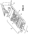
- Each divergent flap 18 includes an inner skin 18i and an outer skin 18o (also illustrated in Figures 2A and 2B).
- the skins 18i, 18o preferably form a multiple of channels 72 which receive the cooling airflow C therethrough from an intake 74 adjacent to the joint structure 69 ( Figures 2A and 2B).
- the divergent flap 18 may be described as having a length 60, defined as extending between a forward end section 62 and an aft end section 64, and a width 66 defined between a first longitudinal side 68 and a second longitudinal side 70 ( Figure 6).
- the forward end section 62 of each divergent flap 18 includes a joint structure 69 that forms a portion of the joint 20 ( Figures 2A, 2B).
- the joint structure 69 corresponds with the divergent flap seal joint structure 42 along the hinge axis H.
- the aft end section 64 is preferably of a chiseled shape to form a serrated nozzle end.
- each divergent flap 18 includes a plow tip section 73 having a multiple of channels 75 ( Figures 2A and 2B), which receive the cooling airflow C from corresponding channels 72 defined within the divergent flap 18 to then discharge the cooling airflow from a plow tip aft end segment.
- the plow tip section 73 is preferably chiseled and includes a hinge point 77 for attachment of an external flap 79 ( Figures 4A and 4B). It should be understood that various plow tip sections planforms and profiles will be usable with the present invention.
- Each divergent flap 18 preferably includes a forward bridge support 76 and an aft bridge support 78 which respectively receive a forward seal bridge bracket 80 and an aft seal bridge bracket 82 which bridge each divergent flap 18 and divergent seal 21 interface to link movement between adjacent divergent flaps 18 and flap seals 21 around the circumference of the nozzle 10.
- a centering linkage assembly 83 is restrained by the flap position guide 44 to further guide the dilation of the nozzle 10 during articulation between the maximum dilated position and the minimal dilated position and obtain generally synchronous movement between the divergent flaps 18 and divergent seals 21. It should be understood that various linkages and guides are usable with the present invention.
- the divergent flap seals 21 slide and at least partially overlap the inner skin 18i of each adjacent divergent flap 18 (also illustrated from the top in Figures 5A and 5B).
- the flap seals 21 form an inner layer within an outer layer defined by the divergent flaps 18 in which a flap seal 21 overlaps each gap between two adjacent divergent flaps 18 relative the nozzle centerline A.
- first longitudinal side 68 of each divergent flap 18 includes a first set of extensions 84 and the second longitudinal side 70 includes a second set of extension 86 (also illustrated in Figure 6).
- the first and second set of extensions 84, 86 extend laterally relative the longitudinal length of the divergent flap 18.
- Each of the extensions of the first set of extension 84 of the divergent flap 18 are located at longitudinal stations different than the longitudinal station of the second set of extensions 86 such that the extensions of adjacent divergent flaps 18 at least partially interfit when the nozzle 10 is in a minimal position ( Figures 5B and 7B), but provide at least partial support for the intermediate flap seal 21 when the nozzle 10 is in the maximum position ( Figures 5A and 7A).
- Each extension within the first and second set of extensions 84, 86 may take various forms and shapes so long as the first set of extensions 84 generally interfit with the second set of extensions 86 when the nozzle is in the minimum dilated position ( Figures 5B and 7B).
- the extensions 84, 86 should be of some complementary shape which permit at least some circumferential overlap between adjacent divergent flap pairs and over the intermediate flap seals.
- the nozzle 10 is in a maximum or afterburning position.
- the divergent flaps 18 are dilated away from a divergent flap seal longitudinal axis L such that the divergent flap seals 21 are at least partially supported on the extensions 84, 86 such that the max circumference of the nozzle is increased ( Figure 8). That is, the sets of extensions provide for an increased dilation of the nozzle 10 which increases the high-mode area ratio schedule.
- the nozzle 10 is in a minimum or non-afterburning position.
- the divergent flaps 18 are dilated toward the divergent flap seal longitudinal axis L such that the extensions 84, 86 interfit to provide the minimum circumference of the nozzle 10 at the low-mode area ratio schedule.
- This provides a relative increase in the area ratio range (nozzle circumference increased in maximum position while nozzle circumference maintained in minimum position; Figure 8) which results in more efficient engine performance with increased engine thrust, fuel efficiency and a significant decrease in actuator loads required to articulate the nozzle between the maximum and minimum positions.
Landscapes
- Engineering & Computer Science (AREA)
- Chemical & Material Sciences (AREA)
- Combustion & Propulsion (AREA)
- Mechanical Engineering (AREA)
- General Engineering & Computer Science (AREA)
- Supercharger (AREA)
- Turbine Rotor Nozzle Sealing (AREA)
- Exhaust Silencers (AREA)
Applications Claiming Priority (1)
| Application Number | Priority Date | Filing Date | Title |
|---|---|---|---|
| US11/231,067 US7624567B2 (en) | 2005-09-20 | 2005-09-20 | Convergent divergent nozzle with interlocking divergent flaps |
Publications (3)
| Publication Number | Publication Date |
|---|---|
| EP1764498A2 true EP1764498A2 (de) | 2007-03-21 |
| EP1764498A3 EP1764498A3 (de) | 2007-08-08 |
| EP1764498B1 EP1764498B1 (de) | 2009-05-06 |
Family
ID=37667354
Family Applications (1)
| Application Number | Title | Priority Date | Filing Date |
|---|---|---|---|
| EP06253792A Not-in-force EP1764498B1 (de) | 2005-09-20 | 2006-07-20 | Konvergente-divergente Düse mit ineinander greifenden divergenten Klappen |
Country Status (4)
| Country | Link |
|---|---|
| US (1) | US7624567B2 (de) |
| EP (1) | EP1764498B1 (de) |
| JP (1) | JP2007085335A (de) |
| DE (1) | DE602006006628D1 (de) |
Cited By (3)
| Publication number | Priority date | Publication date | Assignee | Title |
|---|---|---|---|---|
| EP1820954A1 (de) * | 2006-02-15 | 2007-08-22 | United Technologies Corporation | Konvergent-divergente Düse mit gestützten divergenten Dichtungen |
| EP1767768A3 (de) * | 2005-09-22 | 2008-01-02 | United Technologies Corporation | Düse eines Turbinentriebwerkes |
| GB2448320B (en) * | 2007-04-10 | 2012-04-11 | Pericles Pilidis | Aircraft engine variable nozzle for silencing and performance enhancement |
Families Citing this family (23)
| Publication number | Priority date | Publication date | Assignee | Title |
|---|---|---|---|---|
| US7458221B1 (en) * | 2003-10-23 | 2008-12-02 | The United States Of America As Represented By The Administrator Of The National Aeronautics And Space Administration | Variable area nozzle including a plurality of convexly vanes with a crowned contour, in a vane to vane sealing arrangement and with nonuniform lengths |
| US7721551B2 (en) * | 2006-06-29 | 2010-05-25 | United Technologies Corporation | Fan variable area nozzle for a gas turbine engine fan nacelle |
| US7963099B2 (en) * | 2007-05-21 | 2011-06-21 | General Electric Company | Fluted chevron exhaust nozzle |
| US7926285B2 (en) | 2007-07-18 | 2011-04-19 | General Electric Company | Modular chevron exhaust nozzle |
| US7716932B2 (en) * | 2008-07-24 | 2010-05-18 | Spirit Aerosystems, Inc. | Dilating fan duct nozzle |
| US8991191B2 (en) * | 2009-11-24 | 2015-03-31 | General Electric Company | Thermally actuated passive gas turbine engine compartment venting |
| RU2426905C1 (ru) * | 2009-12-09 | 2011-08-20 | Открытое акционерное общество "Научно-производственное объединение "Сатурн" (ОАО "НПО "Сатурн") | Регулируемое сопло турбореактивного двигателя |
| US9126374B2 (en) | 2010-09-28 | 2015-09-08 | Russell B. Hanson | Iso-grid composite component |
| US8549834B2 (en) | 2010-10-21 | 2013-10-08 | United Technologies Corporation | Gas turbine engine with variable area fan nozzle |
| JP5673405B2 (ja) * | 2011-07-12 | 2015-02-18 | 株式会社Ihi | ジェットエンジンの可変排気ノズル |
| US9810085B2 (en) | 2011-08-22 | 2017-11-07 | United Technologies Corporation | Flap seal for gas turbine engine movable nozzle flap |
| US20130232949A1 (en) * | 2012-03-09 | 2013-09-12 | Gary J. Dillard | Pressure balanced area control of high aspect ratio nozzle |
| US9163582B2 (en) | 2012-05-30 | 2015-10-20 | United Technologies Corporation | Convergent-divergent gas turbine nozzle comprising movable flaps having a variable thickness in a lateral direction |
| US8695540B2 (en) | 2012-06-18 | 2014-04-15 | Aerojet Rocketdyne Of De, Inc. | Fuel-cracking diesel engine system |
| US9689346B2 (en) * | 2013-04-12 | 2017-06-27 | United Technologies Corporation | Gas turbine engine convergent/divergent exhaust nozzle divergent seal with dovetail interface |
| EP3097301B1 (de) * | 2014-01-24 | 2018-05-02 | United Technologies Corporation | Divergenzklappe |
| US9869190B2 (en) | 2014-05-30 | 2018-01-16 | General Electric Company | Variable-pitch rotor with remote counterweights |
| US10072510B2 (en) | 2014-11-21 | 2018-09-11 | General Electric Company | Variable pitch fan for gas turbine engine and method of assembling the same |
| US10100653B2 (en) | 2015-10-08 | 2018-10-16 | General Electric Company | Variable pitch fan blade retention system |
| US11674435B2 (en) | 2021-06-29 | 2023-06-13 | General Electric Company | Levered counterweight feathering system |
| US11795964B2 (en) | 2021-07-16 | 2023-10-24 | General Electric Company | Levered counterweight feathering system |
| US11772809B2 (en) * | 2021-11-27 | 2023-10-03 | Airbus Defence and Space GmbH | Fuselage for an aircraft with fuselage-integrated tailplane |
| US12601271B2 (en) | 2022-10-21 | 2026-04-14 | General Electric Company | Variable pitch fan of a gas turbine engine |
Citations (1)
| Publication number | Priority date | Publication date | Assignee | Title |
|---|---|---|---|---|
| US5000386A (en) | 1989-07-03 | 1991-03-19 | General Electric Company | Exhaust flaps |
Family Cites Families (37)
| Publication number | Priority date | Publication date | Assignee | Title |
|---|---|---|---|---|
| US3972475A (en) * | 1975-07-31 | 1976-08-03 | United Technologies Corporation | Nozzle construction providing for thermal growth |
| US4073441A (en) * | 1976-10-04 | 1978-02-14 | General Electric Company | Gas turbine engine nozzle apparatus including a nozzle flap slot seal |
| US4171093A (en) * | 1977-08-19 | 1979-10-16 | The United States Of America As Represented By The Secretary Of The Air Force | Durability flap and seal liner assembly for exhaust nozzles |
| US4643356A (en) * | 1977-08-31 | 1987-02-17 | United Technologies Corporation | Cooling liner for convergent-divergent exhaust nozzle |
| US4718230A (en) * | 1986-11-10 | 1988-01-12 | United Technologies Corporation | Augmentor liner construction |
| US4747543A (en) * | 1987-04-14 | 1988-05-31 | United Technologies Corporation | Nozzle flap cooling liner |
| US4747542A (en) * | 1987-04-14 | 1988-05-31 | United Technologies Corporation | Nozzle flap edge cooling |
| US5076496A (en) * | 1990-02-05 | 1991-12-31 | General Electric Company | Exhaust nozzle flap seal |
| US5067324A (en) * | 1990-04-04 | 1991-11-26 | United Technologies Corporation | Engine nozzle liner retainer |
| US5060472A (en) * | 1990-04-12 | 1991-10-29 | The United States Of America As Represented By The Secretary Of The Air Force | Insulated cooling liner |
| US5080284A (en) * | 1990-06-25 | 1992-01-14 | United Technologies Corporation | Cooling system for the trailing edge of a liner |
| US5131222A (en) * | 1990-11-28 | 1992-07-21 | The United States Of Americas As Represented By The Secretary Of The Air Force | Thermally valved cooling system for exhaust nozzle systems |
| US5239823A (en) * | 1991-02-26 | 1993-08-31 | United Technologies Corporation | Multiple layer cooled nozzle liner |
| US5115979A (en) * | 1991-05-28 | 1992-05-26 | General Electric Company | Conforming plunger seal assembly |
| US5188292A (en) * | 1991-06-28 | 1993-02-23 | The United States Of America As Represented By The Secretary Of The Air Force | Thermal shields for rotating members in a gas flow path |
| US5239815A (en) * | 1991-09-23 | 1993-08-31 | United Technologies Corporation | Sync-ring assembly for a gas turbine engine exhaust nozzle |
| US5209059A (en) * | 1991-12-27 | 1993-05-11 | The United States Of America As Represented By The Secretary Of The Air Force | Active cooling apparatus for afterburners |
| US5215256A (en) * | 1992-07-16 | 1993-06-01 | Barcza W Kevin | Flap hinge arrangement for a convergent/divergent nozzle |
| US5269467A (en) | 1992-08-03 | 1993-12-14 | General Electric Company | Vectoring exhaust nozzle seal and flap retaining apparatus |
| US5249419A (en) * | 1992-10-07 | 1993-10-05 | The United States Of America As Represented By The Secretary Of The Air Force | Nozzle liner for gas turbine engines |
| US5437411A (en) | 1992-12-14 | 1995-08-01 | General Electric Company | Vectoring exhaust nozzle flap and seal positioning apparatus |
| US5323965A (en) * | 1993-05-26 | 1994-06-28 | The United States Of America As Represented By The Secretary Of The Air Force | Hinge end seal |
| US5524438A (en) | 1994-12-15 | 1996-06-11 | United Technologies Corporation | Segmented bulkhead liner for a gas turbine combustor |
| US5683034A (en) | 1995-05-22 | 1997-11-04 | United Technologies Corporation | Engine exhaust nozzle seal |
| US5560198A (en) | 1995-05-25 | 1996-10-01 | United Technologies Corporation | Cooled gas turbine engine augmentor fingerseal assembly |
| US5839663A (en) | 1996-07-23 | 1998-11-24 | United Technologies Corporation | Gas turbine exhaust nozzle flap and flap seal apparatus |
| US5797544A (en) | 1996-09-27 | 1998-08-25 | United Technologies Corporation | C/D nozzle with synchronizing ring link suspension |
| US5813611A (en) | 1996-09-27 | 1998-09-29 | United Technologies Corporation | Compact pressure balanced fulcrum-link nozzle |
| US5842643A (en) * | 1996-12-03 | 1998-12-01 | General Electric Company | Articulated exhaust nozzle fairing |
| US6398129B1 (en) | 1999-12-29 | 2002-06-04 | United Technologies Corporation | Throat configuration for axisymmetric nozzle |
| US6658854B2 (en) * | 2002-02-01 | 2003-12-09 | General Electric Co. | Methods and apparatus for retaining gas turbine engine nozzle basesheets |
| US6779336B2 (en) * | 2002-07-05 | 2004-08-24 | United Technologies Corporation | Cooled variable geometry exhaust nozzle |
| FR2855559B1 (fr) * | 2003-05-27 | 2005-07-15 | Snecma Moteurs | Systeme d'etancheite du flux secondaire a l'entree d'une tuyere d'une turbomachine avec chambre de post-combustion |
| US7225622B2 (en) | 2003-07-21 | 2007-06-05 | United Technologies Corporation | Turbine engine nozzle |
| US7302793B2 (en) * | 2003-10-29 | 2007-12-04 | General Electric Company | Methods and apparatus to reduce turbine engine nozzle basesheet stresses |
| US7178325B2 (en) * | 2004-05-20 | 2007-02-20 | United Technologies Corporation | Divergent flap for a gas turbine engine |
| US7578133B2 (en) * | 2005-03-28 | 2009-08-25 | United Technologies Corporation | Reduced radar cross section exhaust nozzle assembly |
-
2005
- 2005-09-20 US US11/231,067 patent/US7624567B2/en not_active Expired - Fee Related
-
2006
- 2006-07-20 DE DE602006006628T patent/DE602006006628D1/de active Active
- 2006-07-20 EP EP06253792A patent/EP1764498B1/de not_active Not-in-force
- 2006-07-24 JP JP2006200711A patent/JP2007085335A/ja active Pending
Patent Citations (1)
| Publication number | Priority date | Publication date | Assignee | Title |
|---|---|---|---|---|
| US5000386A (en) | 1989-07-03 | 1991-03-19 | General Electric Company | Exhaust flaps |
Cited By (4)
| Publication number | Priority date | Publication date | Assignee | Title |
|---|---|---|---|---|
| EP1767768A3 (de) * | 2005-09-22 | 2008-01-02 | United Technologies Corporation | Düse eines Turbinentriebwerkes |
| EP1820954A1 (de) * | 2006-02-15 | 2007-08-22 | United Technologies Corporation | Konvergent-divergente Düse mit gestützten divergenten Dichtungen |
| US7624579B2 (en) | 2006-02-15 | 2009-12-01 | United Technologies Corporation | Convergent divergent nozzle with supported divergent seals |
| GB2448320B (en) * | 2007-04-10 | 2012-04-11 | Pericles Pilidis | Aircraft engine variable nozzle for silencing and performance enhancement |
Also Published As
| Publication number | Publication date |
|---|---|
| US20070234728A1 (en) | 2007-10-11 |
| DE602006006628D1 (de) | 2009-06-18 |
| EP1764498B1 (de) | 2009-05-06 |
| US7624567B2 (en) | 2009-12-01 |
| JP2007085335A (ja) | 2007-04-05 |
| EP1764498A3 (de) | 2007-08-08 |
Similar Documents
| Publication | Publication Date | Title |
|---|---|---|
| EP1764498B1 (de) | Konvergente-divergente Düse mit ineinander greifenden divergenten Klappen | |
| EP1820954A1 (de) | Konvergent-divergente Düse mit gestützten divergenten Dichtungen | |
| EP1956225B1 (de) | Konvergent-divergente Düse mit einer kantengekühlten Dichtung | |
| EP1961944B1 (de) | Konvergente-divergente Düse mit schachtgekühlter Düsenauskleidung | |
| US7032835B2 (en) | Convergent/divergent nozzle with modulated cooling | |
| US8769925B2 (en) | Thrust vectorable fan variable area nozzle for a gas turbine engine fan nacelle | |
| US8961114B2 (en) | Integrated variable geometry flow restrictor and heat exchanger | |
| US7174704B2 (en) | Split shroud exhaust nozzle | |
| US7837436B2 (en) | Method and apparatus for regulating fluid flow through a turbine engine | |
| US20160010565A9 (en) | Gas turbine engine with fan variable area nozzle for low fan pressure ratio | |
| EP1378651B1 (de) | Gekühlte Schubdüse mit variabler Geometrie | |
| US11767124B2 (en) | Aircraft propulsion system with variable area inlet | |
| EP3591204B1 (de) | Schubumkehrer mit verschiebbarem hinterkantenkörper | |
| EP3869024B1 (de) | Motornebenkanaldüse mit hohem bypass-verhältnis und kontrollierter düsenfläche | |
| US4892254A (en) | Aircraft engine interface fairing support | |
| EP3816423B1 (de) | Schubdüse für ein gasturbinentriebwerk | |
| US5842643A (en) | Articulated exhaust nozzle fairing | |
| US20150122905A1 (en) | Passive tangential ejector for an exhaust nozzle of a gas turbine engine | |
| EP1995442B1 (de) | Triebwerksventilanordnung |
Legal Events
| Date | Code | Title | Description |
|---|---|---|---|
| PUAI | Public reference made under article 153(3) epc to a published international application that has entered the european phase |
Free format text: ORIGINAL CODE: 0009012 |
|
| AK | Designated contracting states |
Kind code of ref document: A2 Designated state(s): AT BE BG CH CY CZ DE DK EE ES FI FR GB GR HU IE IS IT LI LT LU LV MC NL PL PT RO SE SI SK TR |
|
| AX | Request for extension of the european patent |
Extension state: AL BA HR MK YU |
|
| PUAL | Search report despatched |
Free format text: ORIGINAL CODE: 0009013 |
|
| AK | Designated contracting states |
Kind code of ref document: A3 Designated state(s): AT BE BG CH CY CZ DE DK EE ES FI FR GB GR HU IE IS IT LI LT LU LV MC NL PL PT RO SE SI SK TR |
|
| AX | Request for extension of the european patent |
Extension state: AL BA HR MK YU |
|
| 17P | Request for examination filed |
Effective date: 20071012 |
|
| 17Q | First examination report despatched |
Effective date: 20071113 |
|
| AKX | Designation fees paid |
Designated state(s): DE FR GB IT |
|
| GRAP | Despatch of communication of intention to grant a patent |
Free format text: ORIGINAL CODE: EPIDOSNIGR1 |
|
| GRAS | Grant fee paid |
Free format text: ORIGINAL CODE: EPIDOSNIGR3 |
|
| GRAA | (expected) grant |
Free format text: ORIGINAL CODE: 0009210 |
|
| AK | Designated contracting states |
Kind code of ref document: B1 Designated state(s): DE FR GB IT |
|
| REG | Reference to a national code |
Ref country code: GB Ref legal event code: FG4D |
|
| REF | Corresponds to: |
Ref document number: 602006006628 Country of ref document: DE Date of ref document: 20090618 Kind code of ref document: P |
|
| PLBE | No opposition filed within time limit |
Free format text: ORIGINAL CODE: 0009261 |
|
| STAA | Information on the status of an ep patent application or granted ep patent |
Free format text: STATUS: NO OPPOSITION FILED WITHIN TIME LIMIT |
|
| 26N | No opposition filed |
Effective date: 20100209 |
|
| REG | Reference to a national code |
Ref country code: FR Ref legal event code: ST Effective date: 20100331 |
|
| PG25 | Lapsed in a contracting state [announced via postgrant information from national office to epo] |
Ref country code: FR Free format text: LAPSE BECAUSE OF NON-PAYMENT OF DUE FEES Effective date: 20090731 |
|
| PG25 | Lapsed in a contracting state [announced via postgrant information from national office to epo] |
Ref country code: IT Free format text: LAPSE BECAUSE OF FAILURE TO SUBMIT A TRANSLATION OF THE DESCRIPTION OR TO PAY THE FEE WITHIN THE PRESCRIBED TIME-LIMIT Effective date: 20090506 |
|
| PGFP | Annual fee paid to national office [announced via postgrant information from national office to epo] |
Ref country code: DE Payment date: 20120718 Year of fee payment: 7 |
|
| PG25 | Lapsed in a contracting state [announced via postgrant information from national office to epo] |
Ref country code: DE Free format text: LAPSE BECAUSE OF NON-PAYMENT OF DUE FEES Effective date: 20140201 |
|
| REG | Reference to a national code |
Ref country code: DE Ref legal event code: R119 Ref document number: 602006006628 Country of ref document: DE Effective date: 20140201 |
|
| PGFP | Annual fee paid to national office [announced via postgrant information from national office to epo] |
Ref country code: GB Payment date: 20230620 Year of fee payment: 18 |
|
| GBPC | Gb: european patent ceased through non-payment of renewal fee |
Effective date: 20240720 |
|
| PG25 | Lapsed in a contracting state [announced via postgrant information from national office to epo] |
Ref country code: GB Free format text: LAPSE BECAUSE OF NON-PAYMENT OF DUE FEES Effective date: 20240720 |