EP1764521A2 - Wälzlagereinheit ausgerüstet mit Sensor - Google Patents
Wälzlagereinheit ausgerüstet mit Sensor Download PDFInfo
- Publication number
- EP1764521A2 EP1764521A2 EP06019173A EP06019173A EP1764521A2 EP 1764521 A2 EP1764521 A2 EP 1764521A2 EP 06019173 A EP06019173 A EP 06019173A EP 06019173 A EP06019173 A EP 06019173A EP 1764521 A2 EP1764521 A2 EP 1764521A2
- Authority
- EP
- European Patent Office
- Prior art keywords
- sensor
- bearing ring
- rotary bearing
- detection
- displacement
- Prior art date
- Legal status (The legal status is an assumption and is not a legal conclusion. Google has not performed a legal analysis and makes no representation as to the accuracy of the status listed.)
- Granted
Links
- 238000005096 rolling process Methods 0.000 title claims abstract description 47
- 238000006073 displacement reaction Methods 0.000 claims abstract description 214
- 238000001514 detection method Methods 0.000 claims description 140
- 238000005259 measurement Methods 0.000 claims description 33
- 238000013519 translation Methods 0.000 claims description 28
- 238000004364 calculation method Methods 0.000 claims description 18
- 230000002093 peripheral effect Effects 0.000 claims description 16
- 239000000463 material Substances 0.000 claims description 12
- 238000012937 correction Methods 0.000 claims description 7
- 230000035699 permeability Effects 0.000 claims description 4
- 238000010586 diagram Methods 0.000 description 12
- 239000011159 matrix material Substances 0.000 description 10
- OKTJSMMVPCPJKN-UHFFFAOYSA-N Carbon Chemical compound [C] OKTJSMMVPCPJKN-UHFFFAOYSA-N 0.000 description 7
- 229910052799 carbon Inorganic materials 0.000 description 7
- 230000003247 decreasing effect Effects 0.000 description 6
- 230000005389 magnetism Effects 0.000 description 6
- 230000035945 sensitivity Effects 0.000 description 6
- 238000012545 processing Methods 0.000 description 5
- 229910000831 Steel Inorganic materials 0.000 description 4
- 230000008901 benefit Effects 0.000 description 4
- 239000010959 steel Substances 0.000 description 4
- 229910001209 Low-carbon steel Inorganic materials 0.000 description 3
- 230000000712 assembly Effects 0.000 description 3
- 238000000429 assembly Methods 0.000 description 3
- 238000005255 carburizing Methods 0.000 description 3
- 230000033001 locomotion Effects 0.000 description 3
- 230000004048 modification Effects 0.000 description 3
- 238000012986 modification Methods 0.000 description 3
- 230000015572 biosynthetic process Effects 0.000 description 2
- 230000009545 invasion Effects 0.000 description 2
- 238000004519 manufacturing process Methods 0.000 description 2
- 238000010791 quenching Methods 0.000 description 2
- 230000000171 quenching effect Effects 0.000 description 2
- 230000000717 retained effect Effects 0.000 description 2
- 239000000126 substance Substances 0.000 description 2
- 239000000725 suspension Substances 0.000 description 2
- 229910000976 Electrical steel Inorganic materials 0.000 description 1
- 230000004323 axial length Effects 0.000 description 1
- 239000003990 capacitor Substances 0.000 description 1
- 150000001875 compounds Chemical class 0.000 description 1
- 230000000694 effects Effects 0.000 description 1
- 230000004907 flux Effects 0.000 description 1
- 238000009434 installation Methods 0.000 description 1
- 230000007246 mechanism Effects 0.000 description 1
- 239000002184 metal Substances 0.000 description 1
- 238000000034 method Methods 0.000 description 1
- 230000008569 process Effects 0.000 description 1
- 230000004044 response Effects 0.000 description 1
- 125000006850 spacer group Chemical group 0.000 description 1
- 230000009466 transformation Effects 0.000 description 1
- 238000004804 winding Methods 0.000 description 1
Images


Classifications
-
- F—MECHANICAL ENGINEERING; LIGHTING; HEATING; WEAPONS; BLASTING
- F16—ENGINEERING ELEMENTS AND UNITS; GENERAL MEASURES FOR PRODUCING AND MAINTAINING EFFECTIVE FUNCTIONING OF MACHINES OR INSTALLATIONS; THERMAL INSULATION IN GENERAL
- F16C—SHAFTS; FLEXIBLE SHAFTS; ELEMENTS OR CRANKSHAFT MECHANISMS; ROTARY BODIES OTHER THAN GEARING ELEMENTS; BEARINGS
- F16C19/00—Bearings with rolling contact, for exclusively rotary movement
- F16C19/02—Bearings with rolling contact, for exclusively rotary movement with bearing balls essentially of the same size in one or more circular rows
- F16C19/14—Bearings with rolling contact, for exclusively rotary movement with bearing balls essentially of the same size in one or more circular rows for both radial and axial load
- F16C19/18—Bearings with rolling contact, for exclusively rotary movement with bearing balls essentially of the same size in one or more circular rows for both radial and axial load with two or more rows of balls
- F16C19/181—Bearings with rolling contact, for exclusively rotary movement with bearing balls essentially of the same size in one or more circular rows for both radial and axial load with two or more rows of balls with angular contact
- F16C19/183—Bearings with rolling contact, for exclusively rotary movement with bearing balls essentially of the same size in one or more circular rows for both radial and axial load with two or more rows of balls with angular contact with two rows at opposite angles
- F16C19/184—Bearings with rolling contact, for exclusively rotary movement with bearing balls essentially of the same size in one or more circular rows for both radial and axial load with two or more rows of balls with angular contact with two rows at opposite angles in O-arrangement
- F16C19/186—Bearings with rolling contact, for exclusively rotary movement with bearing balls essentially of the same size in one or more circular rows for both radial and axial load with two or more rows of balls with angular contact with two rows at opposite angles in O-arrangement with three raceways provided integrally on parts other than race rings, e.g. third generation hubs
-
- B—PERFORMING OPERATIONS; TRANSPORTING
- B60—VEHICLES IN GENERAL
- B60B—VEHICLE WHEELS; CASTORS; AXLES FOR WHEELS OR CASTORS; INCREASING WHEEL ADHESION
- B60B27/00—Hubs
- B60B27/0005—Hubs with ball bearings
-
- B—PERFORMING OPERATIONS; TRANSPORTING
- B60—VEHICLES IN GENERAL
- B60B—VEHICLE WHEELS; CASTORS; AXLES FOR WHEELS OR CASTORS; INCREASING WHEEL ADHESION
- B60B27/00—Hubs
- B60B27/0047—Hubs characterised by functional integration of other elements
- B60B27/0068—Hubs characterised by functional integration of other elements the element being a sensor
-
- B—PERFORMING OPERATIONS; TRANSPORTING
- B60—VEHICLES IN GENERAL
- B60B—VEHICLE WHEELS; CASTORS; AXLES FOR WHEELS OR CASTORS; INCREASING WHEEL ADHESION
- B60B27/00—Hubs
- B60B27/0094—Hubs one or more of the bearing races are formed by the hub
-
- F—MECHANICAL ENGINEERING; LIGHTING; HEATING; WEAPONS; BLASTING
- F16—ENGINEERING ELEMENTS AND UNITS; GENERAL MEASURES FOR PRODUCING AND MAINTAINING EFFECTIVE FUNCTIONING OF MACHINES OR INSTALLATIONS; THERMAL INSULATION IN GENERAL
- F16C—SHAFTS; FLEXIBLE SHAFTS; ELEMENTS OR CRANKSHAFT MECHANISMS; ROTARY BODIES OTHER THAN GEARING ELEMENTS; BEARINGS
- F16C19/00—Bearings with rolling contact, for exclusively rotary movement
- F16C19/52—Bearings with rolling contact, for exclusively rotary movement with devices affected by abnormal or undesired conditions
- F16C19/522—Bearings with rolling contact, for exclusively rotary movement with devices affected by abnormal or undesired conditions related to load on the bearing, e.g. bearings with load sensors or means to protect the bearing against overload
-
- F—MECHANICAL ENGINEERING; LIGHTING; HEATING; WEAPONS; BLASTING
- F16—ENGINEERING ELEMENTS AND UNITS; GENERAL MEASURES FOR PRODUCING AND MAINTAINING EFFECTIVE FUNCTIONING OF MACHINES OR INSTALLATIONS; THERMAL INSULATION IN GENERAL
- F16C—SHAFTS; FLEXIBLE SHAFTS; ELEMENTS OR CRANKSHAFT MECHANISMS; ROTARY BODIES OTHER THAN GEARING ELEMENTS; BEARINGS
- F16C33/00—Parts of bearings; Special methods for making bearings or parts thereof
- F16C33/72—Sealings
- F16C33/723—Shaft end sealing means, e.g. cup-shaped caps or covers
-
- G—PHYSICS
- G01—MEASURING; TESTING
- G01L—MEASURING FORCE, STRESS, TORQUE, WORK, MECHANICAL POWER, MECHANICAL EFFICIENCY, OR FLUID PRESSURE
- G01L5/00—Apparatus for, or methods of, measuring force, work, mechanical power, or torque, specially adapted for specific purposes
- G01L5/0009—Force sensors associated with a bearing
- G01L5/0023—Force sensors associated with a bearing by using magnetic sensors
-
- F—MECHANICAL ENGINEERING; LIGHTING; HEATING; WEAPONS; BLASTING
- F16—ENGINEERING ELEMENTS AND UNITS; GENERAL MEASURES FOR PRODUCING AND MAINTAINING EFFECTIVE FUNCTIONING OF MACHINES OR INSTALLATIONS; THERMAL INSULATION IN GENERAL
- F16C—SHAFTS; FLEXIBLE SHAFTS; ELEMENTS OR CRANKSHAFT MECHANISMS; ROTARY BODIES OTHER THAN GEARING ELEMENTS; BEARINGS
- F16C2326/00—Articles relating to transporting
- F16C2326/01—Parts of vehicles in general
- F16C2326/02—Wheel hubs or castors
Definitions
- the present invention relates to a sensor-equipped rolling bearing assembly used for rotatably supporting a wheel of a vehicle such as an automotive vehicle.
- Modern automotive vehicles require a variety of information pieces for providing operation control while the vehicles are moving, the information pieces including, for example, load acting on the road wheel, the number of revolutions thereof.
- the information pieces including, for example, load acting on the road wheel, the number of revolutions thereof.
- a proposal has been made to mount a sensor to a rolling bearing assembly to which the wheel of the vehicle is mounted.
- the conventionally known sensor-equipped rolling bearing assemblies include a bearing assembly which includes: a cylindrical fixed bearing ring fixed to a vehicle body; a rotary bearing ring which is disposed radially inwardly of the fixed bearing ring and to which the wheel is mounted; and a plurality of rows of rolling elements rollably interposed between these bearing rings.
- This bearing assembly has the sensor mounted to the fixed bearing ring such as to acquire information on the rotary bearing ring (see, for example, Japanese Unexamined Patent Publication No.2002-340922 ).
- the fixed bearing ring is formed with a through-hole radially extending therethrough.
- the sensor is fixedly inserted in the through-hole.
- the sensor has its measurement portion confronting an outside surface of the rotary bearing ring, so as to acquire the information on the rotary bearing ring.
- the invention has been accomplished and has an object to provide a sensor-equipped rolling bearing assembly which allows for the omission of the positional adjustment of the respective sensors mounted therein and hence, is easy to assemble.
- Another object of the invention is to provide a sensor-equipped rolling bearing assembly which is adapted to determine a moment load and an axial translation load on the wheel by using only a sensor for detecting physical quantity varying in conjunction with the displacement of a peripheral surface of the rotary bearing ring. That is, the bearing assembly is also applicable to a driving wheel, thus achieving high generality.
- a sensor-equipped rolling bearing assembly comprises: a cylindrical fixed bearing ring fixed to a vehicle body; a rotary bearing ring rotatably inserted through the fixed bearing ring and possessing a wheel-mounting portion on an outboard side thereof; and a plurality of rows of rolling elements rollably interposed between these bearing rings, and is provided with a case member having a plurality of displacement sensors which are circumferentially arranged at predetermined space intervals and which detect gaps between themselves and an outside surface of an inboard end of the rotary bearing ring, the case member being mounted to the inboard end of the fixed bearing ring.
- This constitution negates the need for discretely mounting the displacement sensors to the inboard end of the fixed bearing ring or the need for forming the sensor mounting through-holes in the fixed bearing ring, because the case member possesses the plurality of displacement sensors and is mounted to the inboard end of the fixed bearing ring. Furthermore, the bearing assembly is easy to assemble because the individual displacement sensors are positioned relative to the outside surface of the inboard end of the rotary bearing ring by mounting the case member to the fixed bearing ring.
- the displacement sensor is capable of detecting the variations of the gap between itself and the outside surface of the inboard end of the rotary bearing ring, the gap variations being caused by a radial load applied to the wheel.
- the gap is varied more at the inboard end of the rotary bearing ring than at an axially central portion thereof. Therefore, the displacement sensor can achieve higher detection accuracy by taking measurement on the outside surface of the inboard end.
- the displacement sensor may preferably be an inductance-type displacement sensor. Since the inductance-type displacement sensor is less susceptible to the earth magnetism, a constitution less susceptible to the earth magnetism can be embodied by mounting the bearing assembly equipped with this sensor to the vehicle such as the automotive vehicle which may move in any directions.
- case member further has a second displacement sensor for detecting a gap between itself and an axial-end face of the inboard end of the rotary bearing ring.
- the second displacement sensor can detect the variations of a gap between itself and the axial-end face of the inboard end of the rotary bearing ring, the gap variations being caused by an axial load on the wheel.
- the outside surface of the inboard end of the rotary bearing ring is so configured as to produce radial and axial variations of the gap between the outside surface and the displacement sensors when the load is applied to the rotary bearing ring.
- the displacement sensors circumferentially mounted to the case member are capable of detecting the radial and axial gap variations.
- the rotary bearing ring may be formed with an annular recess in the outside surface of the inboard end thereof confronted by the plurality of displacement sensors.
- the axial displacement of the rotary bearing ring can be detected by the displacement sensors disposed circumferentially of the case member.
- the rotary bearing ring may be formed with an annular band on the outside surface of the inboard end thereof confronted by the plurality of displacement sensors, the annular band being formed from a different material from that of the rotary bearing ring.
- the axial displacement of the rotary bearing ring can be detected by the displacement sensors disposed circumferentially of the case member.
- the displacement sensor is of the inductance type
- an annular measurement subject member which produces a greater inductance variation in the displacement sensors than the rotary bearing ring does, is mounted to the inboard end of the rotary bearing ring, wherein the displacement sensors detect gaps between themselves and an outside surface of the measurement subject member. This results in increased accuracies of the detection by the displacement sensors.
- the displacement sensors may preferably be connected to an arithmetic processor for calculating the respective direction components of the load applied to the rotary bearing ring by way of calculation using respective output values from the displacement sensors and a predetermined function previously stored in the processor.
- This makes it possible to calculate the load on the rotary bearing ring based on the output values from the displacement sensors.
- the predetermined function may be obtained by previously determining the values outputted from the respective displacement sensors in response to the input of the respective direction components of the load.
- a sensor-equipped rolling bearing assembly comprises: a fixed bearing ring having a portion fixed to a vehicle body; a rotary bearing ring disposed coaxially with the fixed bearing ring and having a wheel-mounting portion; a plurality of rows of rolling elements rollably interposed between these bearing rings for permitting these bearing rings to rotate relative to each other; and a sensor device disposed on the fixed bearing ring for detecting physical quantity varying in conjunction with the displacement of a peripheral surface of the rotary bearing ring, and is characterized in that the sensor device comprises a first sensor member and a second sensor member individually detecting the respective physical quantities at axially spaced positions on the peripheral surface of the rotary bearing ring and is connected to a control unit having an arithmetic function to calculate a moment load applied on the wheel based on a difference between detection values obtained by these sensor members.
- the first sensor member and the second sensor member responsible for the detection of the physical quantities varying in conjunction with the displacement of the peripheral surface of the rotary bearing ring are arranged to detect the physical quantities at the axially spaced positions on the peripheral surface of the rotary bearing ring. Therefore, the control unit can calculate the moment load on the wheel based on the difference between the detection values obtained by these sensor members.
- the moment load applied on the wheel may be determined by using only the first and second sensor members for detecting the physical quantities varying in conjunction with the displacement of the peripheral surface of the rotary bearing ring. Therefore, the measurement of the moment load does not require an additional sensor for detecting the axial displacement of the axial-end face of the rotary bearing ring.
- the invention may also be applied to a bearing assembly for driving wheel, to which a constant-velocity joint of a driving shaft is connected.
- a sensor for the other purpose than the load measurement such as an ABS sensor
- the sensor device in a case where the rotary bearing ring is provided with a target portion for producing difference between the detection values from the individual sensor members when the rotary bearing ring is displaced in the same sense of the axial direction, the sensor device may be connected to the control unit also having an arithmetic function to calculate an axial translation load on the wheel based on the difference between the detection values obtained by the individual sensor members.
- control unit connected with the individual sensor members can also calculate the axial translation load on the wheel based on the difference between the detection values obtained by the respective sensor members. It is therefore possible to calculate both the moment load and the axial translation load on the wheel based on the detection values obtained by the above sensor members. Hence, the number of sensors for the load measurement can be decreased insofar as possible.
- the sensor-equipped rolling bearing assembly of the second aspect of the invention may employ the target portion, which includes a first annular detection subject confronting a detection surface of the first sensor member and a second annular detection subject confronting a detection surface of the second sensor member.
- the detection subjects may preferably be so configured and located as to vary the detection values from the sensor members in the opposite signs of plus and minus when the rotary bearing ring is displaced in the same sense of the axial direction.
- a detection value corresponding to an axial unit translation quantity of the rotary bearing ring is amplified by calculating the difference between the detection value from the first sensor member and the detection value from the second sensor member.
- the sensor device as a whole can be increased in the detection sensitivity of the axial displacement.
- the sensor-equipped rolling bearing assembly of the second aspect of the invention may have the following constitution.
- the first sensor member may comprise a first front sensor and a first rear sensor disposed at a front and a rear position of the rotary bearing ring and a first top sensor and a first bottom sensor disposed at a top and a bottom position of the rotary bearing ring
- the second sensor member may comprise a second front sensor and a second rear sensor disposed at a front and a rear position of the rotary bearing ring and a second top sensor and a second bottom sensor disposed at a top and a bottom position of the rotary bearing ring.
- sFy as an independent variable corresponding to a y-axis translation load Fy
- sMz as an independent variable corresponding to a moment load Mz about the z-axis
- sMx as an independent variable corresponding to a moment load Mx about the x-axis
- sFz as an independent variable corresponding to a z-axis translation load Fz
- sFx as an independent variable corresponding to an x-axis translation load Fx
- the above five independent variables sFx, sFy, sFz, sMx and sMz are in linear independent relation with Fx, Fy, Fz, Mx and Mz as actual loads (five component forces) applied to the wheel (see FIG.20). Therefore, if these independent variables sFx, sFy, sFz, sMx and sMz are determined, the five component forces Fx, Fy, Fz, Mx and Mz may be calculated by solving first-degree simultaneous equations with these five component forces Fx, Fy, Fz, Mx and Mz being regarded as unknowns.
- an arithmetic circuit (hardware) and a control program (software) for solving the above equations (5) to (9) and first-degree simultaneous equations with the five unknowns may be installed in the control unit such as an ECU, whereby the loads Fx, Fy, Fz, Mx and Mz actually applied to the wheel can be determined based on the eight detection values f i , r i , t i , b i , f o , r o , t o and b o given by the individual sensors.
- the sensor-equipped rolling bearing assembly of the second aspect of the invention may preferably have a structure wherein the individual sensor members are mounted to a single case member, whereas the case member is mounted to an inboard end of the fixed bearing ring.
- the individual sensor members can be mounted to the fixed bearing ring by merely mounting the case member having the individual sensor members to the inboard end of the fixed bearing ring. This negates the need for discretely mounting the sensor members to the fixed bearing ring or the need for forming the sensor mounting through-holes in the fixed bearing ring. Furthermore, the bearing assembly is easy to assemble because the individual sensor members are positioned relative to the rotary bearing ring by mounting the case member to the fixed bearing ring.
- the individual sensor members in this case are adapted to detect the physical quantities associated with deformation behavior of the inboard end of the rotary bearing ring, which exhibits a greater deformation behavior under external force than the axially central portion (portion near a bearing center) of the rotary bearing ring.
- the sensor members can be increased in the detection accuracies of the physical quantities.
- a sensor element constituting each of the sensor members is not particularly limited but it is preferred to employ the inductance-type displacement sensor.
- Such an inductance-type displacement sensor is less susceptible to the earth magnetism.
- the bearing assembly may be prevented from suffering instable control due to noises caused by the influence of the earth magnetism.
- the above inductance-type displacement sensor is constituted by serially connecting a plurality of coil elements arranged circumferentially of the sensor and each having an independent detection surface, the density of magnetic field produced in one displacement sensor is increased so that the sensor can be increased in the detection sensitivity of the gap between itself and the target portion.
- the detection subjects disposed at the target portion may comprise annular grooves, ridges or slant surfaces formed along a circumferential direction of the target portion, the slant surfaces inclined in mutually different directions.
- each of the detection subjects may also comprise an annular band formed from a material having a different magnetic permeability from that of a material constituting its neighboring portion.
- the detection subject offers an advantage of easy processing and low manufacture cost as compared with the latter case.
- the latter case offers an advantage that the variation of the physical quantity (such as the inductance in the case of the inductance-type displacement sensor) corresponding to an axial unit movement quantity is greater as compared with the former case, so that the detection sensitivity of the physical quantity is increased.
- a sensor-equipped rolling bearing assembly (hereinafter, also referred to simply as “bearing assembly”) according to an embodiment of the invention will hereinbelow be described with reference to the accompanying drawings.
- FIG. is a sectional view showing a bearing assembly according to one embodiment of a first aspect of the invention.
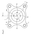
- FIG.2 is a view of this bearing assembly as seen from an inboard side along an axial direction thereof.
- the right-hand side is an outboard side with respect to a vehicle
- the left-hand side is an inboard side with respect to the vehicle.
- the bearing assembly includes: a cylindrical outer ring 1; an inner shaft 2 inserted through the outer ring 1; an inner ring member 3 fitted about an inboard end of the inner shaft 2; double rows of rolling elements 4, 5, each row including a plurality of balls. These components constitute a double-row angular ball bearing.
- the balls in each row as the rolling element 4 or 5 are retained by a cage (not shown) as circumferentially arranged at predetermined space intervals.
- a direction along a centerline C of the bearing assembly is defined as Y-axis
- a horizontal direction orthogonal to the Y-axis is defined as X-axis
- a direction orthogonal to both the Y-axis and X-axis is defined as Z-axis. That is, the Y-axis defines a transversely horizontal direction of the vehicle, the X-axis defines a front-rear horizontal direction thereof, and the Z-axis defines a vertical direction thereof.
- the outer ring 1 constitutes a fixed bearing ring fixed to a vehicle body
- the inner shaft 2 and the inner ring member 3 constitute a rotary bearing ring disposed on a wheel side.
- the double rows of rolling elements 4, 5 are rollably interposed between the fixed bearing ring and the rotary bearing ring.
- the fixed bearing ring and the rotary bearing ring are disposed in coaxial relation such that the rotary bearing ring along with the wheel (not shown) is free to rotate relative to the fixed bearing ring.
- the inner shaft 2 includes a flange 17 which radially outwardly extends from an outboard side thereof.
- the flange 17 serves as a mounting portion for the wheel and a brake disk.
- the wheel and such are mounted to the flange 17 by means of unillustrated bolts.
- the inner ring member 3 is fitted about the inner shaft 2 at an inboard portion thereof.
- the inner ring member 3 is secured to the inner shaft 2 by means of a nut 19 threadedly engaged with the inboard end of the inner shaft 2.
- Respective inner raceway surfaces 14, 15 for the rolling elements 4, 5 are formed on outside surfaces of the inner shaft 2 and of the inner ring member 3.
- the outer ring 1 includes: a cylindrical body 6, an inside surface of which is formed with outer raceway surfaces 12, 13 for the rolling elements 4, 5; and a flange 7 extending radially outwardly from an outside surface of the body 6.
- the flange 7 is fixed to a knuckle (not shown) of a suspension as a vehicular member.
- the bearing assembly is provided with a case member 9 on its inboard side.
- the case member 9 possesses a plurality of displacement sensors for detecting gaps between themselves and an outside surface of an inboard end of the fixed bearing ring.
- the case member 9 is constituted by a cylinder member 31 and a cover member 32.
- the cylinder member 31 is a cylindrical member short in the axial direction.
- the cylinder member 31 has one end thereof fixed to an inboard end of the outer ring 1 by means of a fixing screw 26, so as to be fixed coaxially with the outer ring 1.
- the cover member 32 is fixed to the other end of the cylinder member 31.
- the cover member 32 is mounted in a manner to cap the cylinder member 31 thereby preventing the invasion of foreign substances into a bearing portion.
- a plurality of radial displacement sensors 8 for detecting gaps between themselves and an outside surface of an inboard end of the rotary bearing ring are mounted to an inside surface of the cylinder member 31 of the case member 9.
- FIG.3 shows a state where the cover member 32 of the case member 9 is removed from the bearing assembly.
- the radial displacement sensors 8 (8a, 8b, 8c, 8d) are arranged circumferentially of the case member 9 at predetermined space intervals (90°). Specifically, the radial displacement sensors 8 are disposed at four places including front, rear, top and bottom positions such that the displacement sensors can detect plus or minus variations of radial gaps between themselves and the outside surface of the inboard end of the rotary bearing ring with respect to the X-axis and Z-axis directions.
- These four displacement sensors 8 regard an outside surface of the inner ring member 3 of the rotary bearing ring as a measurement subject 21, and detect gaps between themselves and the outside surface of the inner ring member for determination of radial displacement of the rotary bearing ring.
- the case member 9 is mounted to the inboard end of the outer ring 1 such that the outside surface of the inner ring member 3 may serve as the subject of measurement 21 taken by the displacement sensors 8, which detect gaps between themselves and a shoulder portion of the inner ring member 3.
- the inner ring member 3 Referring to FIG.1, a recessed circumferential groove as the inner raceway surface 15 for the rolling element 5 is formed on the outboard side, whereas the measurement subject 21 is formed on the inboard side as defined by an outside surface portion extending straight in parallel to the axial (Y-axis) direction.
- the inner ring member 3 has a greater axial dimension than that of a stepped small-radius portion 16 which is formed on the inner shaft 2 for allowing the inner ring member 3 to be fitted about the inner shaft. That is, the inner ring member 3 is a cylindrical member longer than a conventional inner ring member.
- the displacement sensor 8 is an inductance-type displacement sensor, which is capable of detecting the variations of the gap between itself and the outside surface of the inner ring member 3 based on inductance variations. More specifically, the displacement sensor 8 includes a pair of magnetic poles 27 adjoining each other in a circumferential direction and each having a sensor coil 28 wound thereabout, as shown in FIG.1 and FIG.3.
- the displacement sensors 8 are disposed at the front, rear, top and bottom positions of the bearing assembly. These magnetic-pole pairs 27 are so formed as to project radially inwardly from a single annular plate 29 and to have their radially inward end-faces confronting the outside surface of the inner ring member 3 via the radial gap.
- the individual magnetic-poles 27 of the radial displacement sensors 8 are formed integrally with the metallic annular plate 29, so that the displacement sensors 8 are adapted to detect the gaps between themselves and the outside surface of the inner ring member 3 with respect to the radial directions (X-axis direction and Z-axis direction).
- the annular plate 29 is fixed to the cylinder member 31 by means of a fixing screw 30 as sandwiched between an inside jaw 31a of the cylinder member 31 and an annular base plate 33.
- the plurality of radial displacement sensors 8 are unified with the case member 9, thus negating the need for adjustment of the circumferential positions thereof or the need for adjustment of the radial positions thereof (distance to the outside surface of the inner ring member 3) in the assembly work of the bearing assembly. Since the plurality of displacement sensors 8 are assembled to the case member 9, the individual displacement sensors 8 can be positioned relative to the measurement subject 21 by mounting the case member 9 to the outer ring 1. This results in an easy assembly work.
- the case member 9 of the bearing assembly shown in FIG. further includes a second displacement sensor 10 (axial displacement sensor) for detecting a gap between itself and an axial-end face of the inboard end of the rotary bearing ring.
- This displacement sensor 10 is mounted to the cover member 32 of the case member 9.
- the displacement sensor is fixed to a bottom plate 32a of the cover member 32 for detecting the gap between itself and the axial-end face of the rotary bearing ring with respect to a direction parallel to the axial direction (Y-axis direction).
- a measurement subject for the displacement sensor 10 is defined by the inboard axial-end face of the rotary bearing ring.
- the axial-end face is defined by a plate member 20 fixed to (threadedly engaged with) the nut 19.
- the plate member 20 has a flat plane 20a orthogonal to the axial direction.
- the flat plane 20a is the measurement subject for the axial displacement sensor 10.
- the axial displacement sensor 10 is an inductance-type displacement sensor, which is capable of detecting inductance variations in the sensor coils thereof.
- each axial displacement sensor 10 is adapted to measure the axial (Y-axis) displacement of the rotary bearing ring, so that an axial load on the wheel can be determined.
- the axial displacement sensors 10 are disposed at top and bottom places (10a, 10b) and in a concentric relation. This provides for the determination of a moment about X-axis Mx of the rotary bearing ring relative to the fixed bearing ring.
- the axial displacement sensors 10 may also be disposed at four places including top, bottom, front and rear places (10a, 10b, 10c, 10d).
- This provides for the determination of a moment about X-axis Mx and a moment about Z-axis Mz of the rotary bearing ring relative to the fixed bearing ring. Specifically, when the moment about X-axis Mx is applied to the rotary bearing ring, the respective gaps between the axial top displacement sensor 10a and the detection subject and between the axial bottom displacement sensor 10b and the detection subject are varied, while the axial displacement sensors 10a, 10b are adapted to measure such gap variations.
- the radial displacement sensors 8 are adapted to take measurements on the gap variations caused by the radial load applied to the wheel in terms of the radial displacement of the inner ring member 3.
- the gap is varied more (amplified) at the inner ring member 3 at the inboard end than at an axially central portion of the inner shaft 2 (portion between the rolling elements 4, 5). Therefore, the accuracy of the measurements taken by the displacement sensors 8 can be increased by using the outside surface of the inner ring member 3 as the measurement subject 21.
- the displacement sensors 8, 10 are of the inductance type which is less susceptible to the earth magnetism, a constitution less susceptible to the earth magnetism can be embodied by mounting the bearing assembly equipped with this sensor to the vehicle such as the automotive vehicle which moves as freely changing the traveling direction thereof. Furthermore, the displacement sensor featuring high durability can be embodied.
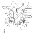
- FIG.4 is a sectional view showing a bearing assembly according to another embodiment of the first aspect of the invention.
- the bearing assembly is generally constituted the same way as the first embodiment shown in FIG.1 but differs therefrom in that the measurement subject 21 for the displacement sensor 8 is defined by a slant surface, that the displacement sensor 8 has an inside end face formed in parallel to this slant surface as defining a gap therebetween, and that the axial displacement sensor is dispensed with.
- FIG.4 omits the depiction of the cover member 32 of the case member 9. This embodiment may also be arranged to omit the cover member 32.
- an outside surface of an inboard end of the inner ring member 3 is formed as a straight slant surface inclined relative to the centerline C, while this slant surface is used as a measurement plane 22 for the displacement sensor 8.
- the configuration of the measurement plane 22 permits the gap between the plane and the radial displacement sensor 8 to be varied in both of the radial direction and the axial direction when the load is applied to the rotary bearing ring.
- the radial displacement sensor 8 is adapted to detect gap variations in both of the radial direction and the axial direction. Hence, a radial displacement and an axial displacement of the rotary bearing ring can be detected by the radial displacement sensor 8.
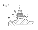
- FIG.5 is a fragmentary sectional view showing a bearing assembly according to still another embodiment of the first aspect of the invention.
- This embodiment also omits the axial displacement sensor similarly to the embodiment shown in FIG.4. Instead, the outside surface of the inboard end of the inner ring member 3 constituting the rotary bearing ring is formed with an annular recess 40 at place confronted by the plurality of displacement sensors 8.
- the annular recess 40 is formed in face-to-face relation with a tip face 8a of the displacement sensor 8. More specifically, a center of the tip face 8a with respect to the axial direction (the axial direction of the bearing assembly) is located above a vehicle-inboard wall 40a of the annular recess 40.
- Such a configuration permits the displacement sensor 8 to detect the axial displacement of the inner ring member 3 because the displacement sensor 8 defines different gaps with respect to the outside surface of the inner ring member 3 and a bottom of the annular recess 40. That is, the displacement sensor disposed radially of the rotary bearing ring can be used for detecting the quantity of axial displacement of the rotary bearing ring.
- FIG.6 is a fragmentary sectional view showing a bearing assembly according to yet another embodiment of the first aspect of the invention.
- This embodiment also omits the axial displacement sensor just as the embodiment shown in FIG.4. Instead, an annular band 50 is formed in the outside surface of the inboard end of the inner ring member 3 constituting the rotary bearing ring and disposed at place confronted by the plurality of displacement sensors 8.
- the annular band is formed from a different material from that of the inner ring member 3.
- the annular band 50 is formed in face-to-face relation with the tip face 8a of the displacement sensor 8. More specifically, the center of the tip face 8a with respect to the axial direction (the axial direction of the bearing assembly) is located above a vehicle-inboard edge 50a of the annular band 50.
- the inductance-type displacement sensor is used as the displacement sensor 8.
- the formation of the annular band 50 from the different material from that of the inner ring member 3 can be implemented by, for example, varying a carbon content of the material forming the inner ring member 3.
- the inner ring member 3 can be coated with anticarburizing compounds at its portion where the annular band 50 is to be formed.
- the inner ring member can be subjected to the carburizing and quenching process, whereby the carbon content of the annular band 50 can be decreased from that of the other portion which is not subjected to the anticarburizing treatment.
- the low carbon steel normally has a carbon content in the range of 0.1 to 0.2%. However, the carbon content of the low carbon steel is increased to about 0.7 to 0.8% by carburizing the steel.
- the portion having the greater carbon content is less transmissive to line of magnetic force than the portion having the smaller carbon content.
- the formation of the annular band 50 provides for the detection of the axial displacement of the inner ring member 3. That is, the displacement sensor disposed radially of the rotary bearing ring can be used for detecting the quantity of axial displacement of the rotary bearing ring. In the embodiment shown in FIG.6, an eddy-current displacement sensor may also be used as the displacement sensor.
- FIG.5 and FIG.6 may also be arranged such that some of the plurality of displacement sensors 8 are disposed in face-to-face relation with the annular recess 40 or the annular band 50 whereas the remaining displacement sensors 8 are not disposed opposite the annular recess 40 or the annular band 50. Such an arrangement provides for the variations of output pattern of the sensors.
- the outside surface of the inner ring member 3 may also have any other configuration than the slant surface in order to produce both the radial and the axial variations of the gap between the outside surface and the radial displacement sensors 8 when the load is applied to the rotary bearing ring.
- the outside surface of the inner ring member may be formed with a recessed circumferential groove.
- an arrangement may be made such that the displacement sensor 8 has its radially inside end positioned in the recessed circumferential groove so as to detect the radial gap variation associated with radial displacement of a bottom of the recessed circumferential groove and to detect the axial gap variation associated with axial displacement of a lateral side of the recessed circumferential groove.
- FIG.7 is a sectional view showing a bearing assembly according to still another embodiment of the first aspect of the invention.
- the bearing assembly is generally constituted the same way as the first embodiment shown in FIG. 1 but differs therefrom in that an annular measurement subject member 23 is fitted about the inboard end of the rotary bearing ring as sandwiched between the inner ring member 3 and the nut 19, whereas the radial displacement sensor 8 is adapted to detect a gap between itself and an outside surface of the measurement subject member 23.
- the figure omits the depiction of the cover member 32 of the case member 9, the plate member 20 and the axial displacement sensor 10.
- This annular measurement subject member 23 is a member (material) which produces a greater inductance variation in the displacement sensor 8 than the inner ring member 3 does.
- the inner ring member 3 is formed from bearing steel, whereas the measurement subject member 23 is formed of a silicon steel sheet.
- the displacement sensor 8 is increased in measurement accuracies.
- the axial displacement can be measured by means of the same axial displacement sensor (not shown) and plate member (not shown) as those shown in FIG.1.
- the plate member may be formed from the same material as that of the measurement subject member 23.
- the same slant surface as that shown in FIG.4 or the unillustrated recessed circumferential groove (measurement plane 22) is formed in an outside surface of the annular measurement subject member 23 such that the radial displacement sensor 8 can take measurements on the radial gap and the axial gap between itself and the rotary bearing ring.
- the axial displacement sensor can be dispensed with.
- correlation between the load acting on the tire (tire force) and the displacement of the rotary bearing ring can be previously established whereby the load can be determined.
- the aforesaid displacement sensors can be used to determine X-axis, Y-axis and Z-axis components (Fsx, Fsy Fsz, Msx, Msz) of the load applied to the rotary bearing ring.
- the radial displacement sensors 8c, 8d at the front and rear positions, the radial displacement sensors 8a, 8b at the top and bottom positions and the axial displacement 10a, 10b at the top and bottom positions are connected to an arithmetic processing unit (not shown).
- the arithmetic processing unit may be implemented in a control unit (ECU) mounted in the vehicle body and is capable of calculating output values from the individual displacement sensors.
- ECU control unit
- FIG.8 shows the displacements of the rotary bearing ring as determined from the output values from the individual displacement sensors when the force/moment is applied to the wheel mounted to the rotary bearing ring.
- FIG.8 graphically represents the individual displacements of the rotary bearing ring as determined from the detection values (gaps) supplied from the radial displacement sensors 8c, 8d at the front and rear positions, the axial displacement sensors 10a, 10b at the top and bottom positions and the radial displacement sensors 8a, 8b at the top and bottom positions when the rotary bearing ring is subjected to the X-axis load (Fx input), Y-axis load (Fy input) and the Z-axis load (Fz input) as the load acting on the wheel and to the moment about the X-axis (Mx input) and the moment about the Z-axis (Mz input) as the moment acting on the wheel.
- Fx input X-axis load
- Fy input Y-axis load
- Fz input Z-axis load
- a general equation (1) represents the correlation of FIG.8 in the form of a determinant (in an arranged form).
- a matrix M of the determinant obtained from the results shown in FIG.8 is represented by an equation (2).
- the equation (1) and equation (2) represent the relation between the individual displacement sensors and the loads/moments in the individual directions in terms of determinant.
- An equation (3) represents an inverse matrix M -1 of the matrix M.
- the components with respect to the individual axes (Fsx, Fsy, Fsz, Msx, Mxz) of the load applied to the wheel (rotary bearing ring) can be calculated based on an equation (4) which uses the values supplied from the individual displacement sensors and the inverse matrix M -1 .
- the individual axes-components (Fsx, Fsy, Fsz, Msx, Mxz) of the load (tire force) applied to the wheel (rotary bearing ring) can be calculated based on the calculation using the output values from the individual displacement sensors and the predetermined function (inverse matrix M -1 ) previously stored in the processing unit.
- the radial displacement sensors 8 are symmetrically disposed at the top-bottom positions and the front-rear positions with respect to the centerline C, so that the need for correction for temperature is negated by calculating a difference between the output values from the corresponding sensor pair.
- ABS sensor (not shown) to the inboard end of the bearing assembly.
- the aforesaid displacement sensors 8, 10 are disposed at the inboard end where the ABS sensor is disposed.
- signal lines 25 of these sensors can be concentrated at the case member 9 at the inboard end of the bearing assembly so that the bearing assembly can have a simplified structure. Furthermore, a wiring operation of these signal lines is facilitated.
- a through-hole 24 may be formed in the case member 9, as shown in FIG.1, so that the signal lines 25 from the individual sensors may be led out through this through-hole 24 for external wiring. At this time, the signal lines 25 may be combined to be collectively passed through the through-hole 24. This negates the need for forming a hole for the signal lines 25 in the outer ring 1.
- the bearing assembly of the invention is not limited to the illustrated embodiments and may be practiced in any other mode within the scope of the invention. While the foregoing embodiments are described by way of examples where the bearing assemblies are used in a driven wheel, for example, the bearing assembly may also be used in a driving wheel.
- the cover member 32 of the case member 9 (see FIG.1) is formed as an annular member (not shown) fitted about a shaft for driving the wheel (rotary bearing ring) into rotation, whereas a seal member is interposed between these members.
- the displacement sensors for detecting the axial displacement of the rotary bearing ring with respect to the axial-end face thereof is disposed at the case member for closing the inboard end of the fixed bearing ring.
- the means permitting the additional installation of the displacement sensor for detecting the axial displacement of the rotary bearing ring with respect to the axial-end face thereof. That is, the means may be adopted by the bearing assembly for driven wheel wherein the axial-end face of the rotary bearing ring defines a free end.
- the means may not be adopted by the bearing assembly for driving wheel wherein the axial-end face of the rotary bearing ring is coupled with a constant-velocity joint of a drive shaft.
- the bearing assembly for driven wheel also has a problem that it is difficult to mount a sensor for the other purpose than load measurement, such as the ABS sensor.
- a bearing assembly for overcoming these drawbacks is so arranged that a sensor device mounted to the fixed bearing ring includes a first sensor member and a second sensor member individually detecting physical quantities at axially spaced positions on a peripheral surface of the rotary bearing ring and is connected to a control unit having an arithmetic function to calculate a moment load on the wheel based on a difference between detection values obtained by these sensor members.
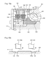
- FIG.9 is a sectional side elevation showing the bearing assembly according to the second aspect of the invention.
- FIG.10a and FIG. 10b are enlarged sectional views showing a sensor portion of the bearing assembly.
- FIG.11 is a view of the bearing assembly as seen from an inboard side.
- FIG.12 is a view of the bearing assembly with a cover member 117 (to be described hereinafter) being removed therefrom, as seen from the inboard side. It is noted that the right-hand side as seen in FIG.9 is the outboard side (the outer side of the vehicle) whereas the left-hand side as seen in the figure is the inboard side (the inner side of the vehicle).
- a bearing assembly 100 includes: a cylindrical outer ring 101; an inner shaft 102 rotatably inserted through the outer ring 101; an inner ring member 103 fitted about an inboard end of the inner shaft 102; a target portion 104 fitted about an inboard end of the inner ring member 103; and a plurality of rows of rolling elements 105, 105 each including a plurality of balls arranged circumferentially.
- These components constitute a double-row angular ball bearing portion.
- the balls in each row, as the rolling element 105, 105, are retained by a cage 106 as circumferentially arranged at predetermined space intervals.
- the outer ring 101 constitutes the fixed bearing ring fixed to the vehicle body.
- the inner shaft 102, the inner ring member 103 and the target portion 104 constitute the rotary bearing ring disposed on the wheel side.
- the plurality of rows of rolling elements 105, 105 are rollably interposed between the fixed bearing ring and the rotary bearing ring.
- the fixed bearing ring and the rotary bearing ring are positioned in coaxial relation.
- the rotary bearing ring is free to rotate together with the wheel (a tire and a tire wheel shown in FIG.21) relative to the fixed bearing ring.
- the inner shaft 102 constituting the rotary bearing ring has a flange 107 extending radially outwardly from the outboard side thereof.
- the flange 107 defines a mounting portion to which the tire wheel of the wheel and a brake disk are mounted.
- the tire wheel and such are mounted to the flange 107 by means of an unillustrated fixing bolt.
- the inner ring member 103 is fitted about a step portion formed on an inboard side of the inner shaft 102.
- the inner ring member 103 is secured to the inner shaft 102 by means of a nut 108 threadedly engaged with an inboard end of the inner shaft 102.
- Respective inner raceway surfaces 109, 109 for rolling elements 105, 105 are formed on respective outside surfaces of the inner shaft 102 and the inner ring member 103.
- the outer ring 101 constituting the fixed bearing ring includes: a cylindrical body 111 having outer raceway surfaces 110, 110 for the rolling elements 105, 105 formed on an inside surface thereof; and a flange 112 extending radially outwardly from an outside surface of the cylindrical body 111.
- the flange 112 is fixed to a knuckle (not shown) of a suspension as a vehicular-side member, whereby the bearing assembly 100 is fixed to the vehicle body.
- the bearing assembly 100 of the embodiment includes: a sensor device 114 for detecting a physical quantity varying in conjunction with the displacement of an outside surface of the target portion 104 disposed on the rotary bearing ring (the embodiment defines the physical quantity as inductance varying in conjunction with a gap between the device and an outside surface of the target portion 104); and a case member 115 for mounting the sensor device 114 to the outer ring 101 as the fixed bearing ring.
- the case member 115 includes a short cylinder member 116 and a disk-like cover member 117.
- the cylinder member 116 consists of a cylindrical metal member having a short axial length.
- the cylinder member 116 has an opening on one end thereof fixed to an inboard end of the outer ring 101 by means of a fixing screw 118 in a manner to establish coaxial relation with the outer ring 101.
- the cover member 117 is a member for closing an opening at the other end of the cylinder member 116, thus serving to prevent the invasion of foreign substances into the bearing assembly 100.
- the sensor device 114 is mounted to an inside surface of the cylinder member 116 of the case member 115 for the purpose of detecting a gap between itself and the outside surface of the target portion 104 fixed to the inboard end of the inner shaft 102.
- the sensor device 114 of the embodiment includes a first sensor member 121 and a second sensor member 122 which detect respective gaps as determined at axially spaced positions on the outside surface of the target portion 104.
- first concerning the sensor device 114 and the target portion 104, means the inboard side whereas the term “second” means the outboard side.
- the first and second sensor members 121, 122 are inductance-type displacement sensors which each detect the variations of the gap between itself and the outside surface of the target portion 104 based on inductance variations.
- the first and second sensor members include: sensor rings 123 mounted to the inside surface of the cylinder member 116 in axially spaced two lines; and a plurality of displacement sensors 124 (four sensors in this embodiment) arranged circumferentially of each sensor ring 123 at predetermined space intervals.
- the sensor rings 123 are fixed to a jaw 116a of the cylinder member 116 by means of a fixing screw 126 as sandwiching a cylindrical spacer 125 therebetween (FIG.9).
- the displacement sensors 124 of each of the first and second sensor members 121, 122 are disposed at four positions including front, rear, top and bottom positions.
- the displacement sensors are so disposed as to detect the variations of the gap between the sensors and the outside surface of the target portion 104 on the rotary bearing ring with respect to the x-axis and the z-axis directions.
- the first sensor member 121 on the inboard side includes: a first front sensor 124f and a first rear sensor 124r disposed at a front and a rear position of the rotary bearing ring; and a first top sensor 124t and a first bottom sensor 124b disposed at a top and a bottom position of the rotary bearing ring.
- the second sensor member 122 on the outboard side also includes: a second front sensor 124f and a second rear sensor 124r disposed at a front and a rear position of the rotary bearing ring; and a second top sensor 124t and a second bottom sensor 124b disposed at top and a bottom position of the rotary bearing ring.
- Each of these eight displacement sensors 124 (f, r, t, b) is constituted by serially connecting a pair of coil elements 127, 127 individually having an independent detection surface to the target portion 104 and closely adjoining each other in the circumferential direction.
- the pair of coil elements 127, 127 are constituted by winding coil about a pair of magnetic poles 128 projecting from an inside surface of the sensor ring 123. These magnetic poles 128 project radially inwardly from the sensor ring 123 so that radial-inboard end faces thereof (detection surfaces) confront the outside surface of the target portion 104 via a radial gap therebetween.
- the first and second sensor members 121, 122 are integrally mounted to the case member 115 to constitute a sensor unit, each sensor member including the four displacement sensors 124 disposed at the front, rear, top and bottom positions.
- the bearing assembly 100 when the bearing assembly 100 is assembled, all the displacement sensors 124 can be mounted to the outer ring 101 simply by mounting the case member 115 to the inboard end of the outer ring 101. This negates the need for discretely mounting each of the displacement sensors 124 to the outer ring 101. What is more, the outer ring 101 need not be formed with through-holes for mounting the sensors.
- the individual displacement sensors 124 can be circumferentially and radially positioned relative to the target portion 104 on the rotary bearing ring by mounting the case member 115 to the outer ring 101. Therefore, each of the displacement sensors 124 need not be mounted as making positional adjustment. This leads to quite an easy assembly work of the bearing assembly 100.
- the displacement sensors 124 incorporated in the case member 115 have an advantage of detecting the gap with increased accuracies because the sensors detect the gap varying in conjunction with the deformation behavior of the target portion 104 located at the inboard end of the rotary bearing ring, which exhibits a greater deformation behavior under external force than that of an axially central portion (portion near the center of the bearing O shown in FIG.9) of the rotary bearing ring.
- the displacement sensors 124 are disposed at places relatively far away from the flange 112 of the outer ring 101, so that the sensors are less affected by the strain of peripheral portions of the flange 112. This leads to an advantage that the sensors are capable of highly accurately detecting the gap variations.
- FIG.13a illustrates an exemplary gap-detecting circuit of the sensor device 114 of the embodiment.
- the sensors 124t, 124b vertically opposing each other (the top sensor and the bottom sensor in FIG.13a and FIG.13b) are connected to an oscillator 130, which supplies an AC current of a certain period to the individual sensors 124t, 124b.
- the sensors 124t, 124b are connected in parallel with respective capacitors 131 for synchronization.
- the embodiment uses a differential amplifier 132 for providing an output voltage (detection value) corresponding to a quantity of vertical displacement by calculating a difference between the output voltages (detection values) from the individual sensors 124t, 124b.
- a differential amplifier 132 for providing an output voltage (detection value) corresponding to a quantity of vertical displacement by calculating a difference between the output voltages (detection values) from the individual sensors 124t, 124b.
- the same differential amplifier as the above is also used to determine a difference between the detection values from the sensors mutually opposing in the horizontal direction, thereby eliminating the temperature-induced drift.
- L A ⁇ ⁇ ⁇ N 2 / d
- L the coil inductance
- A the area of the detection surface
- ⁇ the magnetic permeability
- N the number of coils
- d the distance (gap) between the detection surface and the target 104.
- the inductance L of the displacement sensor 124 is varied so that the output voltage is varied. Therefore, the radial gap between the detection surface of the displacement sensor 124 and the target portion 104 can be detected by detecting the variations of the output voltage.
- one displacement sensor 124 is constituted by serially connecting a pair of coil elements 127 each possessing the independent detection surface to the target portion 104.
- this displacement sensor is adapted to produce magnetic flux in higher density as compared with a case where one displacement sensor 127 is constituted by one coil element 127, as shown in FIG.13b.
- the displacement sensor is further increased in detection sensitivity of the distance to the target portion 104.
- the target portion 104 is formed of a cylindrical member fitted about the inboard end of the inner ring member 103.
- the outside surface of the target portion 104 is formed with a first annular detection subject 134 confronting the detection surface (tip face of the magnetic pole 128) of the first sensor member 121 on the inboard side, and a second annular detection subject 135 confronting the detection surface of the second sensor member 122 on the outboard side.
- these detection subjects 134, 135 are defined by a first and a second annular groove formed along the circumferential direction of the target portion 104.
- the first annular groove 134 on the inboard side 134 is disposed in a manner to have its outboard groove-end face 134a located in proximity of the center of a detection surface A1 of the first sensor member 121
- the second annular groove 135 on the outboard side 135 is disposed in a manner to have its inboard groove-end face 135a located in proximity of the center of a detection surface A2 of the second sensor member 122.
- an axial overlap length between the first sensor member 121 and the first annular groove 134 on the inboard side is decreased so that the first sensor member 121 provides a decreased detection value of the gap.
- an axial overlap length between the second sensor member 122 and the second annular groove 135 on the outboard side is increased so that the second sensor member 122 provides an increased detection value of the gap.
- the first sensor member 121 on the inboard side provides an increased detection value of the gap
- the second sensor member 122 on the outboard side provides a decreased detection value of the gap
- the target portion 104 of the embodiment is provided with a pair of annular grooves 134, 135 on the outside surface thereof, which are axially spaced from each other so as to produce a difference between the detection values obtained by the first and second sensor members 121, 122 when the rotary bearing ring is displaced in the same sense of the axial direction.
- these annular grooves 134, 135 have their axial positions relative to the sensor side defined such that the respective detection values obtained by these sensor members 121, 122 may be varied in the opposite ways (plus and minus) when the rotary bearing ring is displaced in the same sense of the axial direction.
- a detection value for axial unit translation quantity of the rotary bearing ring is amplified by calculating the difference between the detection value from the first sensor member 121 on the inboard side and the detection value from the second sensor member 122 on the outboard side.
- the sensor device as a whole can be increased in the detection sensitivity of the axial displacement.
- the first annular groove 134 on the inboard side may be shifted to the outboard side relative to the detection surface A1 of the first sensor member 121, whereas the second annular groove 135 on the outboard side may be shifted to the inboard side relative to the detection surface A2 of the second sensor member 122.
- This arrangement may also provide the same function and effect as the above.
- the respective displacement sensors 124 constituting the first and second sensor members 121, 122 are connected to the control unit 137, such as the ECU, on the vehicle side by means of a signal line 136 (see FIGS.9 and 11) passed through the cover member 117 of the case member 115.
- the output voltages (detection values) obtained by the individual sensors are calculated by the control unit 137 based on the calculation method to be described hereinafter, whereby individual direction moment loads and translation loads acting on the wheel are determined.
- FIG.19 is a block diagram showing the calculation method taken by the control unit 137.
- a front-rear horizontal direction of the wheel is defined as the x-axis direction
- a lateral horizontal direction (axial direction) of the wheel is defined as the y-axis direction
- a vertical direction of the wheel is defined as the z-axis direction.
- a subscript "i” is attached to the detection value from the inboard sensor (the first sensor member 121), whereas a subscript “o” is attached to the detection value from the outboard sensor (the second sensor member 122).
- the detection value from the front-side sensor is defined as "f(front)”
- the detection value from the rear-side sensor is defined as “r(rear)”
- the detection value from the top-side sensor is defined as "t(top)”
- the detection value from the bottom-side sensor is defined as "b(bottom)”.
- the detection values from a total number of eight sensors disposed at the first and second sensor members 121, 122 are defined as follows:
- sFy calculated based on the following equation (5) is adopted as an independent variable corresponding to the y-axis translation load Fy, as shown in FIG.15b (see a calculation block B1 in FIG.19).
- sFy f i + r i + t i + b i - ( f o + r o + t o + b o )
- the value sFy corresponding to the axial unit translation quantity of the rotary bearing ring is amplified by calculating the difference between the detection values from the inboard sensor and the outboard sensor, whereby the sensor device 114 as a whole can be increased in the detection sensitivity of the axial displacement.
- the detection value of the x-axis displacement is obtained by calculating a difference between the detection value f of the front sensor and the detection value r of the rear sensor, whereas the detection value of the z-axis displacement is obtained by calculating a difference between the detection value t of the top sensor and the detection value b of the bottom sensor.
- the detection value of the x-axis displacement and the detection value of the z-axis displacement can be obtained at the respective positions on the inboard side and the outboard side, as indicated by the following equations.
- the detection value of the x-axis displacement on the inboard side: x i f i - r i .
- the detection value of the z-axis displacement on the inboard side: z i - t i + b i .
- the detection value of the x-axis displacement on the outboard side: x o f o - r o .
- the detection value of the z-axis displacement on the outboard side: z o - t o + b o .
- the detection value corresponding to the moment load Mz about the z-axis can be theoretically defined by a value mz calculated based on the following equation, provided that L i represents an axial distance from the bearing center O to the detection position of the inboard sensor (the first sensor member 121), and that L o represents an axial distance from the bearing center O to the detection position of the outboard sensor (the second sensor member 122). If ⁇ is small enough, this value mz should agree with x i .
- FIG.18a is a linear graph showing a relation between Mz, mz and the detection value x i when only the moment load Mz about the z-axis is applied to the wheel. As indicated by the graph, the slope of the plot mz does not agree with the slope of the plot of the detection value x i .
- a correction coefficient kz obtained by dividing the slope of the plot x i by the slope of the plot mz is introduced in order to establish the agreement between these slopes.
- an independent variable sMz corresponding to the moment load Mz about the z-axis is obtained by multiplying the above value mz by the correction coefficient kz (see calculation blocks B3 and B4 of FIG.19). It is noted that the negative sign (-) on the right side is used for agreement with the sign of another independent variable (such as the above sFy or sMx to be described hereinafter).
- sMz - mz ⁇ kz
- the independent variable sMx corresponding to the moment load Mx about the x-axis can be calculated based on the following equation (7) according to the same concept as that of the variable sMz.
- sMx mx ⁇ kx
- kx in the above equation (7) is a correction coefficient introduced for the same purpose as that of the coefficient kz and is obtained by dividing the slope of the plot z i by the slope of the plot mx (see FIG.18b and FIG.18c).
- the detection value x i of the x-axis displacement on the inboard side contains a component of the independent variable sMz corresponding to the moment load Mz about the z-axis and a component of an independent variable sFx corresponding to the x-axis translation load Fx. Therefore, the independent variable sFx corresponding to the x-axis translation load Fx can be obtained by subtracting the value sMz from the value x i .
- the independent variables sFz corresponding to the z-axis translation load Fz and the independent variable sFx corresponding to the x-axis translation load Fx can be calculated using the following equations (8) and (9), respectively (see a calculation block B4 of FIG. 19).
- sFz z i - mx ⁇ kx
- sFx x i - mz ⁇ kz
- Fig.20 shows matrix charts each showing a correlation between each independent variable sFx, sFy, sFz, sMx, sMz calculated using each of the above equations (5) to (9) and each load Fx, Fy, Fz, Mx, Mz actually applied to the wheel.
- each linear relation between each of the inputs of the loads Fx, Fy, Fz, Mx and Mz actually applied to the wheel and each of the outputs of the independent variables sFx, sFy, sFz, sMx and sMz given by the equations (5) to (9) is graphically shown in the form of matrix.
- the individual loads Fx, Fy, Fz, Mx and Mz can be determined by solving first-degree simultaneous equations with five unknowns of the five loads Fx, Fy, Fz, Mx and Mz applied to the wheel.
- the aforesaid control unit 137 such as the ECU, incorporates therein an arithmetic circuit (hardware) and a control program (software) for solving the aforementioned equations (5) to (9) and the first-degree simultaneous equations with five unknowns. Therefore, the individual loads Fx, Fy, Fz, Mx and Mz actually applied to the wheel can be determined based on the eight detection values f i , r i , t i , b i , f o , r o , t o , b o obtained by the individual sensors.
- annular bands 139, 140 having a greater (or smaller) magnetic permeability than that of the material constituting the peripheral portions thereof may be disposed at the annular grooves 134, 135 of the target portion 104.
- such annular bands 139, 140 may be formed by varying a carbon content of the steel.
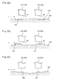
- the detection subjects of the target portion 104 may be constituted by not only the aforementioned annular grooves 134, 135 but also ridges 141, 142 as shown in FIG.22b. Furthermore, the detection subjects may also be constituted by slant surfaces 143, 144 inclined in mutually opposite directions as shown in FIG.22c. While FIG.22c illustrates the slant surfaces 143, 144 defining a trough at their joint, the slant surfaces may also be formed in a manner to define a ridge at their joint.
- the sensor members 121, 122 constituting the sensor device 114 may also be mounted directly to the outer ring 101 rather than to the case member 115. While the foregoing embodiment has the arrangement wherein the outer ring 101 on the outside-circumferential side of the bearing assembly 100 constitutes the fixed bearing ring whereas the inner shaft 102 and the like on the inside-circumferential side constitute the rotary bearing ring, an alternative arrangement may also be made such that the components on the inside-circumferential side constitute the fixed bearing ring whereas the component on the outside-circumferential side constitutes the rotary bearing ring.
- the sensor device 114 of the invention may employ not only the inductance-type displacement sensor but also any other type of non-contact displacement sensors so long as such sensors are capable of detecting the gap.
- the control unit 137 performing the above calculation method and the sensor device 114 connected thereto may be applied not only to the rolling bearing assembly for vehicles but also to, for example, a magnetic bearing assembly for use in other mechanisms than the vehicles.
- the control unit 137 performing the calculation method shown in FIG.19 and the axial double-row sensor device 114 prerequisite for implementing the calculation may be applied to a variety of bearing assemblies serving the needs for taking measurements of a plurality of moment loads and translation loads.
- the invention may be applied to the rolling bearing assembly including the fixed bearing ring, the rotary bearing ring disposed in coaxial relation with the fixed bearing ring and rotatable relative to the fixed bearing ring, and the sensor device disposed on the fixed bearing ring for detecting the physical quantity varying in conjunction with the displacement of the peripheral surface of the rotary bearing ring.
- the sensor device includes the first and second sensor members individually detecting the respective physical quantities at the axially spaced positions on the peripheral surface of the rotary bearing ring.
- the sensor device may be connected to the control unit performing the aforementioned calculation method (for example, the calculation method shown in FIG.20) for calculating the radial moment loads and the axial translation loads based on the detection values obtained by the individual sensor members.
Landscapes
- Engineering & Computer Science (AREA)
- General Engineering & Computer Science (AREA)
- Mechanical Engineering (AREA)
- Chemical & Material Sciences (AREA)
- Analytical Chemistry (AREA)
- Physics & Mathematics (AREA)
- General Physics & Mathematics (AREA)
- Rolling Contact Bearings (AREA)
Applications Claiming Priority (2)
| Application Number | Priority Date | Filing Date | Title |
|---|---|---|---|
| JP2005266481A JP2007078073A (ja) | 2005-09-14 | 2005-09-14 | 車輪用転がり軸受装置 |
| JP2005322651A JP2007127253A (ja) | 2005-11-07 | 2005-11-07 | センサ付き転がり軸受装置 |
Publications (3)
| Publication Number | Publication Date |
|---|---|
| EP1764521A2 true EP1764521A2 (de) | 2007-03-21 |
| EP1764521A3 EP1764521A3 (de) | 2008-11-26 |
| EP1764521B1 EP1764521B1 (de) | 2011-06-01 |
Family
ID=37076329
Family Applications (1)
| Application Number | Title | Priority Date | Filing Date |
|---|---|---|---|
| EP06019173A Not-in-force EP1764521B1 (de) | 2005-09-14 | 2006-09-13 | Wälzlagereinheit ausgerüstet mit Sensor |
Country Status (2)
| Country | Link |
|---|---|
| US (1) | US20070058892A1 (de) |
| EP (1) | EP1764521B1 (de) |
Cited By (5)
| Publication number | Priority date | Publication date | Assignee | Title |
|---|---|---|---|---|
| EP1988377A3 (de) * | 2007-05-01 | 2010-12-29 | Jtekt Corporation | Rollenlagervorrichtung mit Sensor |
| CN102435131A (zh) * | 2011-11-11 | 2012-05-02 | 北京中科科仪技术发展有限责任公司 | 径向位移传感器及磁悬浮分子泵的转子径向位移检测系统 |
| EP1988376B1 (de) * | 2007-05-01 | 2017-06-07 | JTEKT Corporation | Rollenlagervorrichtung mit Sensor |
| WO2018082730A1 (de) * | 2016-11-04 | 2018-05-11 | Schaeffler Technologies AG & Co. KG | Abstandsmessmodul zur messung eines abstandes in einem lager sowie sensorsatz und lageranordnung |
| EP3425225A1 (de) * | 2017-07-04 | 2019-01-09 | Buffalo Machinery Company Limited | Detektionsvorrichtung zur detektion der axialverschiebung einer lagereinheit |
Families Citing this family (15)
| Publication number | Priority date | Publication date | Assignee | Title |
|---|---|---|---|---|
| WO2007088698A1 (ja) * | 2006-01-31 | 2007-08-09 | Ntn Corporation | 駆動車輪用軸受装置 |
| US20080144985A1 (en) * | 2006-12-15 | 2008-06-19 | The Timken Company | Wheel End With Monitoring Capabilities |
| JP4962126B2 (ja) * | 2007-05-01 | 2012-06-27 | 株式会社ジェイテクト | センサ付き転がり軸受装置 |
| JP2008275509A (ja) * | 2007-05-01 | 2008-11-13 | Jtekt Corp | センサ付き転がり軸受装置 |
| DE602008004978D1 (de) * | 2007-12-17 | 2011-03-31 | Jtekt Corp | Wälzlagereinheit mit Sensor |
| JP2014070656A (ja) * | 2012-09-28 | 2014-04-21 | Jtekt Corp | 鉄道車両用軸受装置 |
| US9140578B2 (en) | 2012-12-06 | 2015-09-22 | Industrial Technology Research Institute | Measurement device |
| US9134141B2 (en) | 2012-12-06 | 2015-09-15 | Industrial Technology Research Institute | Measurement device |
| JP5820842B2 (ja) * | 2013-05-08 | 2015-11-24 | 富士重工業株式会社 | 車輪反力検出装置 |
| US9856967B2 (en) * | 2014-04-11 | 2018-01-02 | Cnh Industrial America Llc | Torque estimation for work machine power train |
| US10989626B2 (en) * | 2015-09-29 | 2021-04-27 | The Boeing Company | Systems, methods, and devices for performance monitoring of mechanical assemblies |
| US20200217361A1 (en) * | 2018-03-19 | 2020-07-09 | Schaeffler Technologies AG & Co. KG | Sensor set for bearings, and bearing arrangement |
| JP7408274B2 (ja) * | 2018-06-01 | 2024-01-05 | エドワーズ株式会社 | 真空ポンプ及びセンサターゲット |
| JP7272330B2 (ja) * | 2020-07-22 | 2023-05-12 | トヨタ自動車株式会社 | 車両制御装置 |
| TWI806228B (zh) | 2021-11-08 | 2023-06-21 | 財團法人工業技術研究院 | 用於高速旋轉機械的感測器裝置 |
Family Cites Families (12)
| Publication number | Priority date | Publication date | Assignee | Title |
|---|---|---|---|---|
| US5614822A (en) * | 1994-01-28 | 1997-03-25 | Nsk Ltd. | Rolling bearing unit with rotational speed detection device having a tone wheel and a sensor |
| JP3189624B2 (ja) * | 1994-08-11 | 2001-07-16 | 日本精工株式会社 | 回転速度検出装置付転がり軸受ユニット |
| JPH08184602A (ja) * | 1994-12-28 | 1996-07-16 | Nippon Seiko Kk | 回転速度検出装置付転がり軸受ユニット |
| JP3613899B2 (ja) * | 1996-09-04 | 2005-01-26 | 日本精工株式会社 | 転がり軸受装置の軸振れを低減する方法と軸振れを低減した転がり軸受装置 |
| JP2002340922A (ja) * | 2001-01-25 | 2002-11-27 | Nsk Ltd | 車輪用回転検出装置 |
| JP4135399B2 (ja) * | 2002-05-17 | 2008-08-20 | 株式会社ジェイテクト | センサ付きハブユニット |
| US20060186627A1 (en) * | 2003-03-10 | 2006-08-24 | Katsura Koyagi | Axle-supporting device |
| US20060153482A1 (en) * | 2003-04-07 | 2006-07-13 | Ntn Corporation | Wheel support bearing assembly with built-in load sensor |
| JP4238676B2 (ja) * | 2003-08-29 | 2009-03-18 | 株式会社ジェイテクト | 転がり軸受装置 |
| JP2005114710A (ja) * | 2003-09-19 | 2005-04-28 | Nsk Ltd | 転がり軸受ユニットの荷重測定装置 |
| JP2005172077A (ja) * | 2003-12-10 | 2005-06-30 | Nsk Ltd | 車輪支持用転がり軸受ユニットの荷重測定装置 |
| US7270016B2 (en) * | 2004-12-24 | 2007-09-18 | Jtekt Corporation | Sensor-equipped rolling bearing unit |
-
2006
- 2006-09-12 US US11/519,031 patent/US20070058892A1/en not_active Abandoned
- 2006-09-13 EP EP06019173A patent/EP1764521B1/de not_active Not-in-force
Non-Patent Citations (1)
| Title |
|---|
| None |
Cited By (6)
| Publication number | Priority date | Publication date | Assignee | Title |
|---|---|---|---|---|
| EP1988377A3 (de) * | 2007-05-01 | 2010-12-29 | Jtekt Corporation | Rollenlagervorrichtung mit Sensor |
| EP1988376B1 (de) * | 2007-05-01 | 2017-06-07 | JTEKT Corporation | Rollenlagervorrichtung mit Sensor |
| CN102435131A (zh) * | 2011-11-11 | 2012-05-02 | 北京中科科仪技术发展有限责任公司 | 径向位移传感器及磁悬浮分子泵的转子径向位移检测系统 |
| CN102435131B (zh) * | 2011-11-11 | 2013-08-28 | 北京中科科仪股份有限公司 | 径向位移传感器及磁悬浮分子泵的转子径向位移检测系统 |
| WO2018082730A1 (de) * | 2016-11-04 | 2018-05-11 | Schaeffler Technologies AG & Co. KG | Abstandsmessmodul zur messung eines abstandes in einem lager sowie sensorsatz und lageranordnung |
| EP3425225A1 (de) * | 2017-07-04 | 2019-01-09 | Buffalo Machinery Company Limited | Detektionsvorrichtung zur detektion der axialverschiebung einer lagereinheit |
Also Published As
| Publication number | Publication date |
|---|---|
| EP1764521B1 (de) | 2011-06-01 |
| US20070058892A1 (en) | 2007-03-15 |
| EP1764521A3 (de) | 2008-11-26 |
Similar Documents
| Publication | Publication Date | Title |
|---|---|---|
| EP1764521A2 (de) | Wälzlagereinheit ausgerüstet mit Sensor | |
| US8167499B2 (en) | Rolling bearing device with sensor | |
| EP2085756B1 (de) | Wälzlagervorrichtung für rad | |
| EP1962073B1 (de) | Mit einem sensor ausgestattetes lager für ein rad | |
| US20070157742A1 (en) | Hub unit with sensor | |
| JP2004003918A (ja) | 荷重測定装置付車輪支持用転がり軸受ユニット | |
| EP1873508A2 (de) | Kugellageranordnung für ein Rad | |
| US7819026B2 (en) | Sensor-equipped wheel support bearing assembly | |
| EP1962074B1 (de) | Mit einem sensor ausgestattetes lager für ein rad | |
| JP2004198247A (ja) | 転がり軸受ユニット用荷重測定装置 | |
| JP2007127253A (ja) | センサ付き転がり軸受装置 | |
| US7878713B2 (en) | Sensor-equipped bearing for wheel | |
| US20090169143A1 (en) | Bearing Device for Drive Wheel | |
| US7270016B2 (en) | Sensor-equipped rolling bearing unit | |
| JP4962126B2 (ja) | センサ付き転がり軸受装置 | |
| JP4363103B2 (ja) | センサ付きハブユニット | |
| JP4239758B2 (ja) | センサ付きハブユニット | |
| JP4269674B2 (ja) | 転がり軸受ユニット用荷重測定装置 | |
| JP4218361B2 (ja) | センサ付き転がり軸受ユニット | |
| JP2008275510A (ja) | センサ付き転がり軸受装置 | |
| JP2007078073A (ja) | 車輪用転がり軸受装置 | |
| JP2008275507A (ja) | センサ付き転がり軸受装置 | |
| JP2006177834A (ja) | センサ付き転がり軸受ユニット | |
| JP2005098771A (ja) | 転がり軸受ユニットの荷重測定装置 | |
| JP2006226477A (ja) | センサ付き転がり軸受装置 |
Legal Events
| Date | Code | Title | Description |
|---|---|---|---|
| PUAI | Public reference made under article 153(3) epc to a published international application that has entered the european phase |
Free format text: ORIGINAL CODE: 0009012 |
|
| AK | Designated contracting states |
Kind code of ref document: A2 Designated state(s): AT BE BG CH CY CZ DE DK EE ES FI FR GB GR HU IE IS IT LI LT LU LV MC NL PL PT RO SE SI SK TR |
|
| AX | Request for extension of the european patent |
Extension state: AL BA HR MK YU |
|
| PUAL | Search report despatched |
Free format text: ORIGINAL CODE: 0009013 |
|
| 17P | Request for examination filed |
Effective date: 20080925 |
|
| AK | Designated contracting states |
Kind code of ref document: A3 Designated state(s): AT BE BG CH CY CZ DE DK EE ES FI FR GB GR HU IE IS IT LI LT LU LV MC NL PL PT RO SE SI SK TR |
|
| AX | Request for extension of the european patent |
Extension state: AL BA HR MK RS |
|
| 17Q | First examination report despatched |
Effective date: 20090515 |
|
| AKX | Designation fees paid |
Designated state(s): DE FR IT |
|
| GRAP | Despatch of communication of intention to grant a patent |
Free format text: ORIGINAL CODE: EPIDOSNIGR1 |
|
| GRAS | Grant fee paid |
Free format text: ORIGINAL CODE: EPIDOSNIGR3 |
|
| GRAA | (expected) grant |
Free format text: ORIGINAL CODE: 0009210 |
|
| AK | Designated contracting states |
Kind code of ref document: B1 Designated state(s): DE FR IT |
|
| REG | Reference to a national code |
Ref country code: DE Ref legal event code: R096 Ref document number: 602006022255 Country of ref document: DE Effective date: 20110714 |
|
| PLBE | No opposition filed within time limit |
Free format text: ORIGINAL CODE: 0009261 |
|
| STAA | Information on the status of an ep patent application or granted ep patent |
Free format text: STATUS: NO OPPOSITION FILED WITHIN TIME LIMIT |
|
| 26N | No opposition filed |
Effective date: 20120302 |
|
| PG25 | Lapsed in a contracting state [announced via postgrant information from national office to epo] |
Ref country code: IT Free format text: LAPSE BECAUSE OF FAILURE TO SUBMIT A TRANSLATION OF THE DESCRIPTION OR TO PAY THE FEE WITHIN THE PRESCRIBED TIME-LIMIT Effective date: 20110601 |
|
| REG | Reference to a national code |
Ref country code: DE Ref legal event code: R097 Ref document number: 602006022255 Country of ref document: DE Effective date: 20120302 |
|
| REG | Reference to a national code |
Ref country code: FR Ref legal event code: PLFP Year of fee payment: 10 |
|
| PGFP | Annual fee paid to national office [announced via postgrant information from national office to epo] |
Ref country code: FR Payment date: 20150629 Year of fee payment: 10 |
|
| REG | Reference to a national code |
Ref country code: FR Ref legal event code: ST Effective date: 20170531 |
|
| PG25 | Lapsed in a contracting state [announced via postgrant information from national office to epo] |
Ref country code: FR Free format text: LAPSE BECAUSE OF NON-PAYMENT OF DUE FEES Effective date: 20160930 |
|
| PGFP | Annual fee paid to national office [announced via postgrant information from national office to epo] |
Ref country code: DE Payment date: 20200901 Year of fee payment: 15 |
|
| REG | Reference to a national code |
Ref country code: DE Ref legal event code: R119 Ref document number: 602006022255 Country of ref document: DE |
|
| PG25 | Lapsed in a contracting state [announced via postgrant information from national office to epo] |
Ref country code: DE Free format text: LAPSE BECAUSE OF NON-PAYMENT OF DUE FEES Effective date: 20220401 |