EP1764523B2 - Dispositif d'embrayage à disques multiples - Google Patents
Dispositif d'embrayage à disques multiples Download PDFInfo
- Publication number
- EP1764523B2 EP1764523B2 EP06018425.6A EP06018425A EP1764523B2 EP 1764523 B2 EP1764523 B2 EP 1764523B2 EP 06018425 A EP06018425 A EP 06018425A EP 1764523 B2 EP1764523 B2 EP 1764523B2
- Authority
- EP
- European Patent Office
- Prior art keywords
- clutch device
- carrier
- carrier element
- plate clutch
- piston
- Prior art date
- Legal status (The legal status is an assumption and is not a legal conclusion. Google has not performed a legal analysis and makes no representation as to the accuracy of the status listed.)
- Not-in-force
Links
- 238000007789 sealing Methods 0.000 claims description 45
- 230000005540 biological transmission Effects 0.000 claims description 13
- 238000001816 cooling Methods 0.000 claims description 11
- 229910000831 Steel Inorganic materials 0.000 claims description 7
- 239000010959 steel Substances 0.000 claims description 7
- 239000004033 plastic Substances 0.000 claims description 6
- 239000000463 material Substances 0.000 claims description 2
- 239000004411 aluminium Substances 0.000 claims 1
- 229910052782 aluminium Inorganic materials 0.000 claims 1
- XAGFODPZIPBFFR-UHFFFAOYSA-N aluminium Chemical compound [Al] XAGFODPZIPBFFR-UHFFFAOYSA-N 0.000 claims 1
- 229910052751 metal Inorganic materials 0.000 claims 1
- 239000002184 metal Substances 0.000 claims 1
- 230000008878 coupling Effects 0.000 description 11
- 238000010168 coupling process Methods 0.000 description 11
- 238000005859 coupling reaction Methods 0.000 description 11
- 230000002093 peripheral effect Effects 0.000 description 6
- 238000004519 manufacturing process Methods 0.000 description 5
- 238000000034 method Methods 0.000 description 4
- 230000000712 assembly Effects 0.000 description 3
- 238000000429 assembly Methods 0.000 description 3
- 230000009977 dual effect Effects 0.000 description 2
- 241000446313 Lamella Species 0.000 description 1
- 230000001133 acceleration Effects 0.000 description 1
- 238000005266 casting Methods 0.000 description 1
- 238000010276 construction Methods 0.000 description 1
- 238000005520 cutting process Methods 0.000 description 1
- 238000004512 die casting Methods 0.000 description 1
- 238000006073 displacement reaction Methods 0.000 description 1
- 230000005489 elastic deformation Effects 0.000 description 1
- 238000001746 injection moulding Methods 0.000 description 1
- 239000002991 molded plastic Substances 0.000 description 1
- 230000036316 preload Effects 0.000 description 1
- 238000000926 separation method Methods 0.000 description 1
Images

Classifications
-
- F—MECHANICAL ENGINEERING; LIGHTING; HEATING; WEAPONS; BLASTING
- F16—ENGINEERING ELEMENTS AND UNITS; GENERAL MEASURES FOR PRODUCING AND MAINTAINING EFFECTIVE FUNCTIONING OF MACHINES OR INSTALLATIONS; THERMAL INSULATION IN GENERAL
- F16D—COUPLINGS FOR TRANSMITTING ROTATION; CLUTCHES; BRAKES
- F16D25/00—Fluid-actuated clutches
- F16D25/06—Fluid-actuated clutches in which the fluid actuates a piston incorporated in, i.e. rotating with the clutch
- F16D25/062—Fluid-actuated clutches in which the fluid actuates a piston incorporated in, i.e. rotating with the clutch the clutch having friction surfaces
- F16D25/063—Fluid-actuated clutches in which the fluid actuates a piston incorporated in, i.e. rotating with the clutch the clutch having friction surfaces with clutch members exclusively moving axially
- F16D25/0635—Fluid-actuated clutches in which the fluid actuates a piston incorporated in, i.e. rotating with the clutch the clutch having friction surfaces with clutch members exclusively moving axially with flat friction surfaces, e.g. discs
- F16D25/0638—Fluid-actuated clutches in which the fluid actuates a piston incorporated in, i.e. rotating with the clutch the clutch having friction surfaces with clutch members exclusively moving axially with flat friction surfaces, e.g. discs with more than two discs, e.g. multiple lamellae
-
- F—MECHANICAL ENGINEERING; LIGHTING; HEATING; WEAPONS; BLASTING
- F16—ENGINEERING ELEMENTS AND UNITS; GENERAL MEASURES FOR PRODUCING AND MAINTAINING EFFECTIVE FUNCTIONING OF MACHINES OR INSTALLATIONS; THERMAL INSULATION IN GENERAL
- F16D—COUPLINGS FOR TRANSMITTING ROTATION; CLUTCHES; BRAKES
- F16D25/00—Fluid-actuated clutches
- F16D25/10—Clutch systems with a plurality of fluid-actuated clutches
-
- F—MECHANICAL ENGINEERING; LIGHTING; HEATING; WEAPONS; BLASTING
- F16—ENGINEERING ELEMENTS AND UNITS; GENERAL MEASURES FOR PRODUCING AND MAINTAINING EFFECTIVE FUNCTIONING OF MACHINES OR INSTALLATIONS; THERMAL INSULATION IN GENERAL
- F16D—COUPLINGS FOR TRANSMITTING ROTATION; CLUTCHES; BRAKES
- F16D21/00—Systems comprising a plurality of actuated clutches
- F16D21/02—Systems comprising a plurality of actuated clutches for interconnecting three or more shafts or other transmission members in different ways
- F16D21/06—Systems comprising a plurality of actuated clutches for interconnecting three or more shafts or other transmission members in different ways at least two driving shafts or two driven shafts being concentric
- F16D2021/0661—Hydraulically actuated multiple lamellae clutches
Definitions
- the invention relates to a wet-running multi-plate clutch device, which actuates a disk set by means of a hydraulically actuated piston, wherein the piston is designed in several parts.
- lamella coupling devices are known (eg DE 102 54 066 A1 ) in which a sealing element is arranged axially fixed in an annular groove of a hub.
- the piston is formed on its inner circumference with a cylindrical portion which serves as a counter-sealing surface and shifts relative to the sealing element upon actuation of the multi-plate clutch device.
- the piston is in this case integrally formed and further carries a vulcanized sealing element for sealing the pressure chamber on the outer circumference.
- a disadvantage of this embodiment of the piston is the costly production of the same and the required axial space requirement on the inner circumference of the piston, which results from the travel and the axial extent of the counter-sealing surface.
- Lamellae coupling devices are furthermore known, which are actuated via an integrally formed piston.
- the piston has at its inner circumference and its outer circumference an annular groove for receiving a sealing ring, which seal the pressure chamber.
- the piston is associated with a centrifugal pressure compensation chamber, which is sealed by a arranged in an annular groove on the outer circumference of the centrifugal pressure compensating chamber wall sealing ring.
- the disadvantage here is the large wall thickness of the piston, which is necessary to incorporate an annular groove without affecting the stability of the piston. A weight-optimized design of the piston as a sheet steel part is therefore not possible.
- a lamellae coupling device for torque transmission in a drive train of a motor vehicle between a drive unit and a transmission wherein the coupling device has at least one, by means of a hydraulically actuated piston, operable disk set, which rotatably arranged with an inner disk carrier inner disks and with an outer disk carrier rotatably disposed outer disks wherein for cooling the plate pack, the plate clutch device is flowed through by a cooling oil supply device cooling oil, wherein the at least one piston is formed in several parts and it is associated with a connected to the cooling oil supply device centrifugal pressure compensation chamber, said at least one piston from a radially inner support member and a radially outer actuating element is formed.
- the centrifugal compensation chamber is formed by a compensation cover, which is arranged on the radially outer actuating element of the two-part piston.
- the advantage here is that the different parts of the piston can be produced separately, whereby the manufacturing costs compared to one-piece piston of the same size can be reduced, since in faulty production of one of the parts is not the complete piston committee.
- the individual parts of the piston are produced in different manufacturing processes.
- the carrier element has annular grooves for receiving sealing elements, which seal the pressure chamber and the pressure compensation chamber.
- the carrier element is preferably provided on its outer circumference and / or its inner circumference with annular grooves.
- the advantage here is that separate cost-effective sealing elements can be used in the annular grooves and a scorching of sealing elements on the piston deleted.
- a respective annular groove for sealing the pressure chamber and the pressure compensation chamber are arranged on the outer circumference and on the inner circumference of an annular groove for receiving a common sealing element between the pressure chamber and pressure equalization chamber.
- An advantageous embodiment of the sealing elements provides in this case that the sealing elements are designed as lip seals or molded seals. As a result, the hysteresis in the system is advantageously kept small.
- the carrier element has on its outer circumference an axial stop for axial securing of the actuating element.
- the carrier element has a further annular groove, in which a retaining ring is arranged, which serves as an axial stop for the actuating element.
- you can the axial stop are formed by a radial shoulder of the carrier element.
- a particularly advantageous embodiment further provides that the actuating element is secured against rotation relative to the carrier element.
- the carrier element has on its outer circumference at least one radially outwardly projecting nubs, which engages positively in a corresponding recess on the inner circumference of the actuating element.
- the carrier element consists of a different material than the actuating element.
- the carrier element is at least partially made of plastic.
- the support element is produced in an injection molding or die casting process. The advantage here is the cost manufacturability of the support element, which has a relation to the actuator compact design. Another advantage is the ease of manufacture of the annular grooves, which can be incorporated in a support element made of plastic already in the casting process, whereby no further process step is necessary.
- the actuating element is made of sheet steel, preferably in a deep-drawing process.
- An advantage of the embodiment of sheet steel is the axial stiffness of the disk-shaped actuating element.
- the small axial space requirement of the actuating element is very advantageous, whereby the axial space requirement of the actuating element is determined substantially only from the travel of the piston.
- Fig.1 is a dual clutch device 1 with two radially arranged clutch assemblies 2,4 is shown.
- the outer disk 6 of the radially outer clutch assembly rotatably but axially displaceable in the outer disk carrier 8 are arranged.
- the inner disks 10 are rotatably connected to the inner disk carrier 12, which is rotatably connected via the hub 14 with the inner transmission input shaft 16.
- the outer disk 7 of the radially inner clutch assembly 4 are rotatably but axially slidably disposed in the outer disk carrier 9.
- the inner disks 11 are rotatably connected to the inner disk carrier 13, which is rotatably connected via the hub 15 with the outer transmission input shaft 17.
- the coupling device 1 is on the input side via the bearing assembly 18, which is located between an axial region of the outer disk carrier 8 and a fixed to the transmission housing cover 20, stored in the transmission housing.
- the torque generated by the drive unit is transmitted via a torsional vibration damper, not shown, to the input hub 22, which is welded to the outer disk carrier.
- To actuate the two clutch assemblies 2,4 serve the two actuators 24, 26, which compress the disk packs when actuated.
- the actuating elements 24, 26 are connected to the two carrier elements 28, 30 arranged radially inside.
- the carrier element 28, which is made of plastic, is provided on its outer circumference with two annular grooves 32, 34, in which the sealing elements 33, 35 are arranged.
- the sealing element 35 seals the pressure chamber 36 radially on the outside, which is formed by the carrier element 28 and the driver disc 38.
- the drive plate 38 is rotatably connected at its outer periphery with the outer disk carrier 8 and rotatably connected at its inner periphery to the hub 40, preferably radially inside and outside welded.
- the pressure compensation chamber 42 is formed by the carrier element 28 and the outer disk carrier 9 of the inner clutch, which is non-rotatably connected to the hub 40. After radially outward, the pressure equalization chamber 42 is sealed by the sealing element 33, which is sealingly guided on an axial inner peripheral region of the outer disk carrier 9.
- the pressure chamber 36 and the pressure compensation chamber 42 are sealed with the sealing element 44, which is arranged in an annular groove on the inner circumference of the carrier element 28 and seals the carrier element against the hub 40.
- the actuating element is supported in the direction of the transmission on the securing element 46, which is arranged in a further annular groove on the outer circumference of the carrier element 28.
- the actuating piston of the radially inner clutch assembly is constructed in two parts in an analogous manner and consists essentially of the support member 30 and the actuator 26. However, the actuator is not supported by a circlip but via a radial stop of the support member 30.
- the pressure chamber 50 is from the outer disc carrier.
- the pressure compensation chamber 54 is formed by the carrier element 30 and the wall 56, which is fixedly arranged at the axial end of the hub 40.
- the pressure compensation chamber 54 is sealed radially outward by the sealing element 58, which is arranged in an annular groove on the outer circumference of the carrier element 30 and is guided on an axial inner peripheral surface of the wall 56.
- the pressure chamber 50 and the pressure compensation chamber 54 are sealed by the sealing member 60 against each other, which is arranged in an annular groove on the inner circumference of the support member 30 and sealingly guided on the hub 40. Due to the radially outer sealing of the two pressure chambers 36, 50 and the two pressure equalization chambers 42 and 54, each with a separate sealing element, the outer diameter of the pressure chamber with respect to its associated pressure equalization chamber can be performed independently, whereby set overcompensation or undercompensation of the centrifugal force caused by the rotating pressure oil can be.
- the axial expansion area 66 of the outer disk carrier 9 of the inner clutch is used on its inner peripheral surface as a sealing surface for the sealing element 33, which the pressure compensation chamber 42 of the radially outer coupling radially outward seals off.
- the axial extension portion 66 of the outer disk carrier 9 on its outer peripheral surface as a sealing surface for the sealing element 52, which seals the pressure chamber 50 of the inner clutch radially outward.
- the sealing radius of the pressure chamber 50 is greater in this case by the wall thickness of the outer disk carrier 9 in the axial extension region 66.
- the two carrier elements In the region of the axial extension region 66 of the outer disk carrier 9, the two carrier elements have an axial overlap region, whereby the overall axial extent of the hub can be reduced by the length of the overlap region of the carrier elements.
- the two sealing elements 33, 55 which on the one hand seal the pressure equalization chamber of the radially outer coupling and on the other hand the pressure chamber of the radially inner coupling, essentially lie opposite one another and use the same axial displacement region on the opposite sides of the axial region 66 ,
- identical sealing elements 33, 35, 44, 52, 58, 60 are used for the two carrier elements 30, 28.
- the oil feed element 62 is arranged radially inside the hub 40 and has on the outer circumference ring channels 63, 64, 65, which correspond to the rotating feed channels of the hub 40.
- the annular channels 63, 64, 65 are connected to axial channels within the hub, via which pressure oil, or compensating oil is pumped from a hydraulic unit, not shown, into the clutch interior. Furthermore, cooling oil for cooling the disk packs is conveyed into the clutch inside via the stationary oil feed element 62.
- the cooling oil emerges from the axial end of the oil feed element 62 into the clutch interior and, due to the centrifugal force, flows radially outward through the disk packs.
- the two centrifugal pressure compensating chambers 42, 54 are in this case in the cooling oil path, or are connected to the cooling oil passages of the hub 40.
- the compensation chamber 54 is in this case supplied by the axially exiting from the hub cooling oil, since this axially flows along the inner circumference of the hub 40 due to the centrifugal force with rotating clutch to then reach radially outward.
- the expansion chamber 54 is filled via the radial opening in the hub.
- the coupling arrangement is mounted on the stationary oil supply element 66 via the bearing arrangement 67.
- the hub 40 on an inside fold for receiving the bearing assembly 67. Since no torque is transmitted via the oil feed element 66, this can be designed according to the invention in several parts and at least partially made of plastic.
- the ⁇ lzuGermanelement 66 essentially consist of two telescoped sleeves, wherein the radially inner on its outer peripheral surface has axial channels and the radially outer sleeve, the annular grooves 63, 64, 65 and further adjacent each Has annular grooves for receiving sealing elements.
- at least one of the sleeve components or both may consist of plastic.
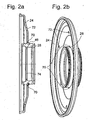
- Fig. 2a shows the support member 28 and the actuator 24 in a sectional view.
- the cutting plane passes through the securing elements 70 of the carrier element 28.
- the two securing elements 70 are arranged directly next to the annular groove, which receives the securing element 46, opposite and formed as radially projecting nubs.
- the actuating element 24 has on its inner circumference corresponding recesses, in which engage the knobs form fit. When planting the actuating element 24 on the securing element 46, the knobs are in the plane of the actuating element 24 and thus act as anti-rotation.
- the actuator 24 is formed as a cold-formed steel cover and further has radial openings 72, whereby a pressure equalization, or a medium flow from the front to the back of the actuator 24 can be carried out.
- the support member 28 is formed as a molded plastic part and has on the outer periphery of the two annular grooves 32, 34, which serve to receive the sealing of the pressure chamber and the pressure compensation chamber sealing elements.
- On the inner circumference of the support member 28 of the radially inwardly stationary shoulder 74 is arranged, which serves as an axial stop of the sealing element, which seals the pressure chamber to the pressure compensation chamber.
- Fig. 2b the support member 28 is shown in assembly with the actuator 24 in a spatial representation. Clearly visible here are the two securing elements 70 of the carrier element 28. Furthermore, the rotationally symmetrical on the circumference of the actuating element 24 arranged radial openings 72 are shown
Landscapes
- Engineering & Computer Science (AREA)
- General Engineering & Computer Science (AREA)
- Mechanical Engineering (AREA)
- Hydraulic Clutches, Magnetic Clutches, Fluid Clutches, And Fluid Joints (AREA)
- General Details Of Gearings (AREA)
Claims (8)
- Dispositif d'embrayage à disques (1) pour le transfert de couple dans une chaîne cinématique d'un véhicule automobile entre une unité d'entraînement et une boîte de vitesses, le dispositif d'embrayage présentant au moins un paquet de disques pouvant être commandé au moyen d'un piston à commande hydraulique, lequel paquet de disques présente des disques internes (10, 11) disposés de manière solidaire en rotation avec un support de disques internes (12, 13) et des disques externes (6, 7) disposés de manière solidaire en rotation avec un support de disques externes (8, 9), le dispositif d'embrayage à disques (1) étant parcouru par de l'huile de refroidissement fournie par un dispositif d'alimentation en huile de refroidissement en vue du refroidissement du paquet de disques, l'au moins un piston étant réalisé en plusieurs parties et étant associé à un espace d'équilibrage de la pression de la force centrifuge (42, 54) raccordé au dispositif d'alimentation en huile de refroidissement, l'au moins un piston étant formé d'un élément de support radialement interne (28, 30) et d'un élément d'actionnement radialement externe (24, 26) et l'élément de support (28, 30) étant en liaison fonctionnelle par le biais d'une première surface active avec un espace de pression (36, 50) et par le biais d'une deuxième surface active avec l'espace d'équilibrage de la pression (33, 54), les deux surfaces actives étant disposées à l'opposé l'une de l'autre,
caractérisé en ce que l'élément de support (28, 30) se compose au moins en partie de plastique - Dispositif d'embrayage à disques selon la revendication 1,
caractérisé en ce que
l'élément de support (28, 30) présente des rainures annulaires (32, 34) pour recevoir des éléments d'étanchéité (33, 35, 44, 52, 58, 60), lesquels réalisent l'étanchéité de l'espace de pression (36, 50) et de l'espace d'équilibrage de la pression (33, 54). - Dispositif d'embrayage à disques selon la revendication 1,
caractérisé en ce que
l'élément de support (28, 30) présente, au niveau de sa périphérie extérieure, une butée axiale (46) pour la fixation axiale de l'élément d'actionnement (24, 26). - Dispositif d'embrayage à disques selon la revendication 1,
caractérisé en ce que
l'élément de support (28, 30) est fixé en rotation par rapport à l'élément d'actionnement (24, 26). - Dispositif d'embrayage à disques selon la revendication 1,
caractérisé en ce que
l'élément de support (28, 30) se compose d'un matériau différent de l'élément d'actionnement (24, 26). - Dispositif d'embrayage à disques selon la revendication 1,
caractérisé en ce que
l'élément de support (28, 30) se compose au moins en partie de métal, par exemple d'aluminium. - Dispositif d'embrayage à disques selon la revendication 1,
caractérisé en ce que
l'élément d'actionnement (24, 26) se compose de tôle d'acier. - Dispositif d'embrayage à disques selon la revendication 1,
caractérisé en ce que
les bagues d'étanchéité insérées dans les rainures sont réalisées sous forme de joints d'étanchéité à lèvre ou de joints d'étanchéité profilés afin de maintenir petite l'hystérésis dans le système.
Applications Claiming Priority (1)
| Application Number | Priority Date | Filing Date | Title |
|---|---|---|---|
| DE102005044227A DE102005044227A1 (de) | 2005-09-16 | 2005-09-16 | Lamellen-Kupplungseinrichtung |
Publications (4)
| Publication Number | Publication Date |
|---|---|
| EP1764523A2 EP1764523A2 (fr) | 2007-03-21 |
| EP1764523A3 EP1764523A3 (fr) | 2009-08-05 |
| EP1764523B1 EP1764523B1 (fr) | 2014-06-11 |
| EP1764523B2 true EP1764523B2 (fr) | 2017-10-25 |
Family
ID=37440751
Family Applications (1)
| Application Number | Title | Priority Date | Filing Date |
|---|---|---|---|
| EP06018425.6A Not-in-force EP1764523B2 (fr) | 2005-09-16 | 2006-09-04 | Dispositif d'embrayage à disques multiples |
Country Status (2)
| Country | Link |
|---|---|
| EP (1) | EP1764523B2 (fr) |
| DE (1) | DE102005044227A1 (fr) |
Families Citing this family (7)
| Publication number | Priority date | Publication date | Assignee | Title |
|---|---|---|---|---|
| DE102008060580B4 (de) * | 2008-06-03 | 2021-01-21 | Borgwarner Inc. | Mehrfach-Kupplungseinrichtung mit zwei Druckausgleichsräumen |
| DE102008055681B4 (de) * | 2008-10-28 | 2020-10-15 | Magna Pt B.V. & Co. Kg | Doppelkupplungsanordnung für ein Doppelkupplungsgetriebe |
| DE102011006029B4 (de) * | 2011-03-24 | 2020-02-27 | Zf Friedrichshafen Ag | Dichtungsanordnung für nasslaufende Doppelkupplung |
| WO2013020540A1 (fr) | 2011-08-11 | 2013-02-14 | Schaeffler Technologies AG & Co. KG | Stator pour un embrayage à friction |
| DE102013204974B4 (de) | 2012-04-12 | 2022-02-24 | Schaeffler Technologies AG & Co. KG | Doppelkupplung |
| DE102014209618B4 (de) * | 2013-06-17 | 2022-12-22 | Schaeffler Technologies AG & Co. KG | Mehrfachkupplungseinrichtung |
| CN117120738A (zh) * | 2021-03-29 | 2023-11-24 | 麦格纳Pt有限两合公司 | 具有支撑盘的多重片式离合器装置、尤其三重片式离合器 |
Citations (15)
| Publication number | Priority date | Publication date | Assignee | Title |
|---|---|---|---|---|
| US3823802A (en) † | 1972-08-18 | 1974-07-16 | Caterpillar Tractor Co | Clutch with controlled coolant flow |
| EP0230106A2 (fr) † | 1985-12-13 | 1987-07-29 | General Motors Corporation | Piston commandé par fluide |
| JPH0628419A (ja) † | 1992-07-07 | 1994-02-04 | Nec Corp | Cadシステム |
| DE4239233A1 (de) † | 1992-11-21 | 1994-05-26 | Daimler Benz Ag | Druckmittelbetätigte, axial ein- und ausrückbare Reibungskupplung |
| DE19521281A1 (de) † | 1995-06-10 | 1996-12-12 | Schaeffler Waelzlager Kg | Kolbenstange für einen Geberzylinder einer hydraulisch betätigten Reibungskupplung |
| EP0762004A2 (fr) † | 1995-08-29 | 1997-03-12 | Honda Giken Kogyo Kabushiki Kaisha | Structure de lubrification d'un embrayage multi-disque |
| FR2745871A1 (fr) † | 1996-03-07 | 1997-09-12 | Renault | Dispositif d'accouplement pour transmission automatique et cloche d'entree correspondante |
| JPH11182579A (ja) † | 1997-12-18 | 1999-07-06 | Nissan Motor Co Ltd | 自動変速機用油圧クラッチおよびこのクラッチを具える自動変速機 |
| FR2786836A1 (fr) † | 1998-12-02 | 2000-06-09 | Valeo | Recepteur hydraulique, notamment d'embrayage, essentiellement en matiere plastique |
| DE10146837A1 (de) † | 2000-09-22 | 2002-05-08 | Valeo | Kraftübertagungsvorrichtung mit Zahnradgetriebe,insbesondere für Kraftfahrzeuge |
| DE10124213A1 (de) † | 2000-12-07 | 2002-06-13 | Zf Sachs Ag | Kupplungseirichtung mit einer wenigstens zwei gleichsinnig geschichtete Tellerfedern aufweisenden Tellerfederanordnung |
| EP1382875A1 (fr) † | 2002-07-18 | 2004-01-21 | BorgWarner Inc. | Embrayage humide ou frein à plaque de friction |
| EP1522753A1 (fr) † | 2003-10-11 | 2005-04-13 | BorgWarner Inc. | Embrayage double hydraulique |
| EP1568906A1 (fr) † | 2004-02-27 | 2005-08-31 | BorgWarner Inc. | Embrayage double |
| WO2006125046A1 (fr) † | 2005-05-17 | 2006-11-23 | Borgwarner Inc. | Mecanisme de double embrayage pour boite de vitesses |
Family Cites Families (3)
| Publication number | Priority date | Publication date | Assignee | Title |
|---|---|---|---|---|
| DE19961988A1 (de) * | 1999-12-22 | 2001-07-05 | Zahnradfabrik Friedrichshafen | Einrichtung zur gleichzeitigen Drehmomentübertragung und axialen Sicherung zweier drehmomentführender Bauteile |
| DE50001452D1 (de) * | 2000-10-05 | 2003-04-17 | Ford Global Tech Inc | Doppelkupplung für ein Getriebe mit zwei Getriebeeingangswellen |
| JP2005320991A (ja) * | 2004-05-06 | 2005-11-17 | Toyota Motor Corp | 自動変速機のクラッチ装置 |
-
2005
- 2005-09-16 DE DE102005044227A patent/DE102005044227A1/de not_active Withdrawn
-
2006
- 2006-09-04 EP EP06018425.6A patent/EP1764523B2/fr not_active Not-in-force
Patent Citations (15)
| Publication number | Priority date | Publication date | Assignee | Title |
|---|---|---|---|---|
| US3823802A (en) † | 1972-08-18 | 1974-07-16 | Caterpillar Tractor Co | Clutch with controlled coolant flow |
| EP0230106A2 (fr) † | 1985-12-13 | 1987-07-29 | General Motors Corporation | Piston commandé par fluide |
| JPH0628419A (ja) † | 1992-07-07 | 1994-02-04 | Nec Corp | Cadシステム |
| DE4239233A1 (de) † | 1992-11-21 | 1994-05-26 | Daimler Benz Ag | Druckmittelbetätigte, axial ein- und ausrückbare Reibungskupplung |
| DE19521281A1 (de) † | 1995-06-10 | 1996-12-12 | Schaeffler Waelzlager Kg | Kolbenstange für einen Geberzylinder einer hydraulisch betätigten Reibungskupplung |
| EP0762004A2 (fr) † | 1995-08-29 | 1997-03-12 | Honda Giken Kogyo Kabushiki Kaisha | Structure de lubrification d'un embrayage multi-disque |
| FR2745871A1 (fr) † | 1996-03-07 | 1997-09-12 | Renault | Dispositif d'accouplement pour transmission automatique et cloche d'entree correspondante |
| JPH11182579A (ja) † | 1997-12-18 | 1999-07-06 | Nissan Motor Co Ltd | 自動変速機用油圧クラッチおよびこのクラッチを具える自動変速機 |
| FR2786836A1 (fr) † | 1998-12-02 | 2000-06-09 | Valeo | Recepteur hydraulique, notamment d'embrayage, essentiellement en matiere plastique |
| DE10146837A1 (de) † | 2000-09-22 | 2002-05-08 | Valeo | Kraftübertagungsvorrichtung mit Zahnradgetriebe,insbesondere für Kraftfahrzeuge |
| DE10124213A1 (de) † | 2000-12-07 | 2002-06-13 | Zf Sachs Ag | Kupplungseirichtung mit einer wenigstens zwei gleichsinnig geschichtete Tellerfedern aufweisenden Tellerfederanordnung |
| EP1382875A1 (fr) † | 2002-07-18 | 2004-01-21 | BorgWarner Inc. | Embrayage humide ou frein à plaque de friction |
| EP1522753A1 (fr) † | 2003-10-11 | 2005-04-13 | BorgWarner Inc. | Embrayage double hydraulique |
| EP1568906A1 (fr) † | 2004-02-27 | 2005-08-31 | BorgWarner Inc. | Embrayage double |
| WO2006125046A1 (fr) † | 2005-05-17 | 2006-11-23 | Borgwarner Inc. | Mecanisme de double embrayage pour boite de vitesses |
Also Published As
| Publication number | Publication date |
|---|---|
| EP1764523A3 (fr) | 2009-08-05 |
| DE102005044227A1 (de) | 2007-03-29 |
| EP1764523A2 (fr) | 2007-03-21 |
| EP1764523B1 (fr) | 2014-06-11 |
Similar Documents
| Publication | Publication Date | Title |
|---|---|---|
| DE102009039223B4 (de) | Doppelkupplungsanordnung für ein Getriebe mit zwei Eingangswellen | |
| DE102004012948B4 (de) | Doppelkupplungseinrichtung in axialer Bauart | |
| EP2310702B1 (fr) | Embrayage double | |
| EP1195537B1 (fr) | Double embrayage pour une transmission avec deux arbres d'entrée | |
| DE102007039856B4 (de) | Kraftübertragungseinrichtung | |
| EP1664567B1 (fr) | Dispositif d'embrayage, en particulier embrayage a disques pour une boite de vitesses a embrayage double | |
| DE10034677A1 (de) | Mehrfachkupplungsanordnung | |
| EP2732175B1 (fr) | Assemblage d'un dispositif de débrayage et d'une cloche d'embrayage | |
| EP1582759A1 (fr) | Système d'actionnement hydraulique pour embrayage. | |
| DE102013216333A1 (de) | Mehrfachkupplungsvorrichtung, insbesondere Doppelkupplungsvorrichtung | |
| DE102011107696A1 (de) | Ausrückereinheit für eine Doppelkupplung | |
| EP1764523B2 (fr) | Dispositif d'embrayage à disques multiples | |
| DE102007027122A1 (de) | Kupplungshauptnabe bzw. Doppelkupplung mit einer derartigen Kupplungshauptnabe | |
| EP1361374B1 (fr) | Système d'embrayage pour véhicule automobile ou similaire | |
| DE102011006029A1 (de) | Dichtungsanordnung für nasslaufende Doppelkupplung | |
| DE20310015U1 (de) | Kupplungseinrichtung, insbesondere Doppel- oder Mehrfachkupplungseinrichtung, und Dichtungskonzept hierfür | |
| DE102015213873A1 (de) | Axiale Lamellenkupplung | |
| EP3759371B1 (fr) | Système d'embrayage et unité d'entraînement présentant ce système d'embrayage | |
| DE4343917C2 (de) | Viskokupplung | |
| EP1602846B1 (fr) | Dispositif d'embrayage | |
| EP1521005A2 (fr) | Unité d'embrayage et/ou de frein | |
| DE102019002850A1 (de) | Kupplungseinrichtung und Antriebsstrang mit einer solchen Kupplungseinrichtung | |
| EP1489328B1 (fr) | Dispositif d'embrayage à disques multiples. | |
| EP1489324B1 (fr) | Dispositif d'embrayage, notamment dispositif d'embrayage double ou multiple et concept d'étanchéité | |
| EP1857699B1 (fr) | Cylindre recépteur |
Legal Events
| Date | Code | Title | Description |
|---|---|---|---|
| PUAI | Public reference made under article 153(3) epc to a published international application that has entered the european phase |
Free format text: ORIGINAL CODE: 0009012 |
|
| AK | Designated contracting states |
Kind code of ref document: A2 Designated state(s): AT BE BG CH CY CZ DE DK EE ES FI FR GB GR HU IE IS IT LI LT LU LV MC NL PL PT RO SE SI SK TR |
|
| AX | Request for extension of the european patent |
Extension state: AL BA HR MK YU |
|
| PUAL | Search report despatched |
Free format text: ORIGINAL CODE: 0009013 |
|
| AK | Designated contracting states |
Kind code of ref document: A3 Designated state(s): AT BE BG CH CY CZ DE DK EE ES FI FR GB GR HU IE IS IT LI LT LU LV MC NL PL PT RO SE SI SK TR |
|
| AX | Request for extension of the european patent |
Extension state: AL BA HR MK RS |
|
| 17P | Request for examination filed |
Effective date: 20091207 |
|
| 17Q | First examination report despatched |
Effective date: 20100125 |
|
| AKX | Designation fees paid |
Designated state(s): AT BE BG CH CY CZ DE DK EE ES FI FR GB GR HU IE IS IT LI LT LU LV MC NL PL PT RO SE SI SK TR |
|
| GRAP | Despatch of communication of intention to grant a patent |
Free format text: ORIGINAL CODE: EPIDOSNIGR1 |
|
| INTG | Intention to grant announced |
Effective date: 20140123 |
|
| GRAS | Grant fee paid |
Free format text: ORIGINAL CODE: EPIDOSNIGR3 |
|
| GRAA | (expected) grant |
Free format text: ORIGINAL CODE: 0009210 |
|
| AK | Designated contracting states |
Kind code of ref document: B1 Designated state(s): AT BE BG CH CY CZ DE DK EE ES FI FR GB GR HU IE IS IT LI LT LU LV MC NL PL PT RO SE SI SK TR |
|
| REG | Reference to a national code |
Ref country code: GB Ref legal event code: FG4D Free format text: NOT ENGLISH |
|
| REG | Reference to a national code |
Ref country code: CH Ref legal event code: EP |
|
| REG | Reference to a national code |
Ref country code: IE Ref legal event code: FG4D Free format text: LANGUAGE OF EP DOCUMENT: GERMAN |
|
| REG | Reference to a national code |
Ref country code: AT Ref legal event code: REF Ref document number: 672418 Country of ref document: AT Kind code of ref document: T Effective date: 20140715 |
|
| REG | Reference to a national code |
Ref country code: DE Ref legal event code: R096 Ref document number: 502006013790 Country of ref document: DE Effective date: 20140724 |
|
| PG25 | Lapsed in a contracting state [announced via postgrant information from national office to epo] |
Ref country code: FI Free format text: LAPSE BECAUSE OF FAILURE TO SUBMIT A TRANSLATION OF THE DESCRIPTION OR TO PAY THE FEE WITHIN THE PRESCRIBED TIME-LIMIT Effective date: 20140611 Ref country code: LT Free format text: LAPSE BECAUSE OF FAILURE TO SUBMIT A TRANSLATION OF THE DESCRIPTION OR TO PAY THE FEE WITHIN THE PRESCRIBED TIME-LIMIT Effective date: 20140611 Ref country code: GR Free format text: LAPSE BECAUSE OF FAILURE TO SUBMIT A TRANSLATION OF THE DESCRIPTION OR TO PAY THE FEE WITHIN THE PRESCRIBED TIME-LIMIT Effective date: 20140912 |
|
| REG | Reference to a national code |
Ref country code: NL Ref legal event code: VDEP Effective date: 20140611 |
|
| REG | Reference to a national code |
Ref country code: LT Ref legal event code: MG4D |
|
| PG25 | Lapsed in a contracting state [announced via postgrant information from national office to epo] |
Ref country code: SE Free format text: LAPSE BECAUSE OF FAILURE TO SUBMIT A TRANSLATION OF THE DESCRIPTION OR TO PAY THE FEE WITHIN THE PRESCRIBED TIME-LIMIT Effective date: 20140611 Ref country code: LV Free format text: LAPSE BECAUSE OF FAILURE TO SUBMIT A TRANSLATION OF THE DESCRIPTION OR TO PAY THE FEE WITHIN THE PRESCRIBED TIME-LIMIT Effective date: 20140611 |
|
| PG25 | Lapsed in a contracting state [announced via postgrant information from national office to epo] |
Ref country code: EE Free format text: LAPSE BECAUSE OF FAILURE TO SUBMIT A TRANSLATION OF THE DESCRIPTION OR TO PAY THE FEE WITHIN THE PRESCRIBED TIME-LIMIT Effective date: 20140611 Ref country code: PT Free format text: LAPSE BECAUSE OF FAILURE TO SUBMIT A TRANSLATION OF THE DESCRIPTION OR TO PAY THE FEE WITHIN THE PRESCRIBED TIME-LIMIT Effective date: 20141013 Ref country code: SK Free format text: LAPSE BECAUSE OF FAILURE TO SUBMIT A TRANSLATION OF THE DESCRIPTION OR TO PAY THE FEE WITHIN THE PRESCRIBED TIME-LIMIT Effective date: 20140611 Ref country code: ES Free format text: LAPSE BECAUSE OF FAILURE TO SUBMIT A TRANSLATION OF THE DESCRIPTION OR TO PAY THE FEE WITHIN THE PRESCRIBED TIME-LIMIT Effective date: 20140611 Ref country code: RO Free format text: LAPSE BECAUSE OF FAILURE TO SUBMIT A TRANSLATION OF THE DESCRIPTION OR TO PAY THE FEE WITHIN THE PRESCRIBED TIME-LIMIT Effective date: 20140611 Ref country code: CZ Free format text: LAPSE BECAUSE OF FAILURE TO SUBMIT A TRANSLATION OF THE DESCRIPTION OR TO PAY THE FEE WITHIN THE PRESCRIBED TIME-LIMIT Effective date: 20140611 |
|
| PG25 | Lapsed in a contracting state [announced via postgrant information from national office to epo] |
Ref country code: IS Free format text: LAPSE BECAUSE OF FAILURE TO SUBMIT A TRANSLATION OF THE DESCRIPTION OR TO PAY THE FEE WITHIN THE PRESCRIBED TIME-LIMIT Effective date: 20141011 Ref country code: NL Free format text: LAPSE BECAUSE OF FAILURE TO SUBMIT A TRANSLATION OF THE DESCRIPTION OR TO PAY THE FEE WITHIN THE PRESCRIBED TIME-LIMIT Effective date: 20140611 Ref country code: PL Free format text: LAPSE BECAUSE OF FAILURE TO SUBMIT A TRANSLATION OF THE DESCRIPTION OR TO PAY THE FEE WITHIN THE PRESCRIBED TIME-LIMIT Effective date: 20140611 |
|
| REG | Reference to a national code |
Ref country code: DE Ref legal event code: R026 Ref document number: 502006013790 Country of ref document: DE |
|
| PLBI | Opposition filed |
Free format text: ORIGINAL CODE: 0009260 |
|
| 26 | Opposition filed |
Opponent name: BORGWARNER, INC. Effective date: 20150311 |
|
| PLAX | Notice of opposition and request to file observation + time limit sent |
Free format text: ORIGINAL CODE: EPIDOSNOBS2 |
|
| PG25 | Lapsed in a contracting state [announced via postgrant information from national office to epo] |
Ref country code: LU Free format text: LAPSE BECAUSE OF FAILURE TO SUBMIT A TRANSLATION OF THE DESCRIPTION OR TO PAY THE FEE WITHIN THE PRESCRIBED TIME-LIMIT Effective date: 20140904 Ref country code: DK Free format text: LAPSE BECAUSE OF FAILURE TO SUBMIT A TRANSLATION OF THE DESCRIPTION OR TO PAY THE FEE WITHIN THE PRESCRIBED TIME-LIMIT Effective date: 20140611 Ref country code: IT Free format text: LAPSE BECAUSE OF FAILURE TO SUBMIT A TRANSLATION OF THE DESCRIPTION OR TO PAY THE FEE WITHIN THE PRESCRIBED TIME-LIMIT Effective date: 20140611 Ref country code: MC Free format text: LAPSE BECAUSE OF FAILURE TO SUBMIT A TRANSLATION OF THE DESCRIPTION OR TO PAY THE FEE WITHIN THE PRESCRIBED TIME-LIMIT Effective date: 20140611 |
|
| REG | Reference to a national code |
Ref country code: CH Ref legal event code: PL |
|
| REG | Reference to a national code |
Ref country code: DE Ref legal event code: R026 Ref document number: 502006013790 Country of ref document: DE Effective date: 20150311 |
|
| GBPC | Gb: european patent ceased through non-payment of renewal fee |
Effective date: 20140911 |
|
| REG | Reference to a national code |
Ref country code: IE Ref legal event code: MM4A |
|
| REG | Reference to a national code |
Ref country code: FR Ref legal event code: ST Effective date: 20150529 |
|
| PG25 | Lapsed in a contracting state [announced via postgrant information from national office to epo] |
Ref country code: BE Free format text: LAPSE BECAUSE OF NON-PAYMENT OF DUE FEES Effective date: 20140930 |
|
| PG25 | Lapsed in a contracting state [announced via postgrant information from national office to epo] |
Ref country code: CH Free format text: LAPSE BECAUSE OF NON-PAYMENT OF DUE FEES Effective date: 20140930 Ref country code: SI Free format text: LAPSE BECAUSE OF FAILURE TO SUBMIT A TRANSLATION OF THE DESCRIPTION OR TO PAY THE FEE WITHIN THE PRESCRIBED TIME-LIMIT Effective date: 20140611 Ref country code: GB Free format text: LAPSE BECAUSE OF NON-PAYMENT OF DUE FEES Effective date: 20140911 Ref country code: LI Free format text: LAPSE BECAUSE OF NON-PAYMENT OF DUE FEES Effective date: 20140930 |
|
| PLAF | Information modified related to communication of a notice of opposition and request to file observations + time limit |
Free format text: ORIGINAL CODE: EPIDOSCOBS2 |
|
| PG25 | Lapsed in a contracting state [announced via postgrant information from national office to epo] |
Ref country code: FR Free format text: LAPSE BECAUSE OF NON-PAYMENT OF DUE FEES Effective date: 20140930 Ref country code: IE Free format text: LAPSE BECAUSE OF NON-PAYMENT OF DUE FEES Effective date: 20140904 |
|
| PLBB | Reply of patent proprietor to notice(s) of opposition received |
Free format text: ORIGINAL CODE: EPIDOSNOBS3 |
|
| REG | Reference to a national code |
Ref country code: AT Ref legal event code: MM01 Ref document number: 672418 Country of ref document: AT Kind code of ref document: T Effective date: 20140904 |
|
| PG25 | Lapsed in a contracting state [announced via postgrant information from national office to epo] |
Ref country code: AT Free format text: LAPSE BECAUSE OF NON-PAYMENT OF DUE FEES Effective date: 20140904 |
|
| PG25 | Lapsed in a contracting state [announced via postgrant information from national office to epo] |
Ref country code: BG Free format text: LAPSE BECAUSE OF FAILURE TO SUBMIT A TRANSLATION OF THE DESCRIPTION OR TO PAY THE FEE WITHIN THE PRESCRIBED TIME-LIMIT Effective date: 20140611 |
|
| PG25 | Lapsed in a contracting state [announced via postgrant information from national office to epo] |
Ref country code: CY Free format text: LAPSE BECAUSE OF FAILURE TO SUBMIT A TRANSLATION OF THE DESCRIPTION OR TO PAY THE FEE WITHIN THE PRESCRIBED TIME-LIMIT Effective date: 20140611 |
|
| PG25 | Lapsed in a contracting state [announced via postgrant information from national office to epo] |
Ref country code: HU Free format text: LAPSE BECAUSE OF FAILURE TO SUBMIT A TRANSLATION OF THE DESCRIPTION OR TO PAY THE FEE WITHIN THE PRESCRIBED TIME-LIMIT; INVALID AB INITIO Effective date: 20060904 Ref country code: TR Free format text: LAPSE BECAUSE OF FAILURE TO SUBMIT A TRANSLATION OF THE DESCRIPTION OR TO PAY THE FEE WITHIN THE PRESCRIBED TIME-LIMIT Effective date: 20140611 |
|
| PUAH | Patent maintained in amended form |
Free format text: ORIGINAL CODE: 0009272 |
|
| STAA | Information on the status of an ep patent application or granted ep patent |
Free format text: STATUS: PATENT MAINTAINED AS AMENDED |
|
| 27A | Patent maintained in amended form |
Effective date: 20171025 |
|
| AK | Designated contracting states |
Kind code of ref document: B2 Designated state(s): AT BE BG CH CY CZ DE DK EE ES FI FR GB GR HU IE IS IT LI LT LU LV MC NL PL PT RO SE SI SK TR |
|
| REG | Reference to a national code |
Ref country code: DE Ref legal event code: R102 Ref document number: 502006013790 Country of ref document: DE |
|
| PGFP | Annual fee paid to national office [announced via postgrant information from national office to epo] |
Ref country code: DE Payment date: 20170830 Year of fee payment: 12 |
|
| PG25 | Lapsed in a contracting state [announced via postgrant information from national office to epo] |
Ref country code: LV Free format text: LAPSE BECAUSE OF FAILURE TO SUBMIT A TRANSLATION OF THE DESCRIPTION OR TO PAY THE FEE WITHIN THE PRESCRIBED TIME-LIMIT Effective date: 20140611 |
|
| REG | Reference to a national code |
Ref country code: DE Ref legal event code: R119 Ref document number: 502006013790 Country of ref document: DE |
|
| PG25 | Lapsed in a contracting state [announced via postgrant information from national office to epo] |
Ref country code: DE Free format text: LAPSE BECAUSE OF NON-PAYMENT OF DUE FEES Effective date: 20190402 |