EP1764543A2 - Dispositif destiné à la reproduction de données - Google Patents
Dispositif destiné à la reproduction de données Download PDFInfo
- Publication number
- EP1764543A2 EP1764543A2 EP06450122A EP06450122A EP1764543A2 EP 1764543 A2 EP1764543 A2 EP 1764543A2 EP 06450122 A EP06450122 A EP 06450122A EP 06450122 A EP06450122 A EP 06450122A EP 1764543 A2 EP1764543 A2 EP 1764543A2
- Authority
- EP
- European Patent Office
- Prior art keywords
- unit
- screen unit
- support column
- base housing
- screen
- Prior art date
- Legal status (The legal status is an assumption and is not a legal conclusion. Google has not performed a legal analysis and makes no representation as to the accuracy of the status listed.)
- Withdrawn
Links
Images




Classifications
-
- F—MECHANICAL ENGINEERING; LIGHTING; HEATING; WEAPONS; BLASTING
- F16—ENGINEERING ELEMENTS AND UNITS; GENERAL MEASURES FOR PRODUCING AND MAINTAINING EFFECTIVE FUNCTIONING OF MACHINES OR INSTALLATIONS; THERMAL INSULATION IN GENERAL
- F16M—FRAMES, CASINGS OR BEDS OF ENGINES, MACHINES OR APPARATUS, NOT SPECIFIC TO ENGINES, MACHINES OR APPARATUS PROVIDED FOR ELSEWHERE; STANDS; SUPPORTS
- F16M11/00—Stands or trestles as supports for apparatus or articles placed thereon ; Stands for scientific apparatus such as gravitational force meters
- F16M11/20—Undercarriages with or without wheels
- F16M11/24—Undercarriages with or without wheels changeable in height or length of legs, also for transport only, e.g. by means of tubes screwed into each other
-
- F—MECHANICAL ENGINEERING; LIGHTING; HEATING; WEAPONS; BLASTING
- F16—ENGINEERING ELEMENTS AND UNITS; GENERAL MEASURES FOR PRODUCING AND MAINTAINING EFFECTIVE FUNCTIONING OF MACHINES OR INSTALLATIONS; THERMAL INSULATION IN GENERAL
- F16M—FRAMES, CASINGS OR BEDS OF ENGINES, MACHINES OR APPARATUS, NOT SPECIFIC TO ENGINES, MACHINES OR APPARATUS PROVIDED FOR ELSEWHERE; STANDS; SUPPORTS
- F16M11/00—Stands or trestles as supports for apparatus or articles placed thereon ; Stands for scientific apparatus such as gravitational force meters
- F16M11/02—Heads
- F16M11/04—Means for attachment of apparatus; Means allowing adjustment of the apparatus relatively to the stand
- F16M11/06—Means for attachment of apparatus; Means allowing adjustment of the apparatus relatively to the stand allowing pivoting
- F16M11/10—Means for attachment of apparatus; Means allowing adjustment of the apparatus relatively to the stand allowing pivoting around a horizontal axis
Definitions
- the invention relates to a device for information reproduction, entertainment and / or data processing, with at least one adjustably mounted screen unit, which is arranged on a vertical support column via a connected to the support column, laterally projecting from this horizontal support arm cantilevered and adjustable in height, and with an input device ,
- a device which is designed in particular as an entertainment device for playing computer games and which has a convex front in which the screen unit is also integrated.
- Below the screen unit are other facilities, such as a card reader, a coin inserter and the like facilities.
- This training entails that this device or its input devices can be operated only when standing or can, but not while sitting, since the lower part of the device is the legs of a seated person in the way.
- this screen unit can not be tilted back and forth about a horizontal axis, but can only be pivoted about vertical axes.
- the device according to the invention should not only be used as a game or entertainment device, but also for information reproduction or data processing, in particular also applications in public places, airports, in hotels or at railway stations, such as information on arrival or departure or Departure times, for ticketing, information reproduction and the like are conceivable.
- a use as a jukebox or time recording system would be possible.
- the objective device should be able to be used practically anywhere an interaction between a user and the device should take place.
- the device can accordingly be designed with its own intelligence, that is to say with a built-in computer, or else merely as a terminal with a connection to a central computer.
- the aim now is to ensure good operability and readability of information on the screen unit, without dislocations of the user are required.
- This problem is particularly serious in training as an electronic entertainment device, as already indicated above, but it is also given in the other applications.
- Aufabe of the invention is therefore to provide a device of the initially mentioned kind so that an optimal operability and extraction of information by reading on the screen unit without twisting the body or head is made possible, nonetheless, a use of the device while sitting should be possible. Furthermore, it is within the scope of this general aim also an object of the invention to allow for different usage options also a corresponding adjustment of the screen unit, so that an operation is possible not only while sitting, but also standing up in a comfortable manner. Nevertheless, the design and assembly of the device should be as simple as possible, yet stable in operation, and the device should also be distinguished by a pleasing appearance.
- the inventive device of the type mentioned is therefore characterized in particular by the fact that the support column is mounted in a base housing and height adjustable via a drive unit, and that the screen unit is mounted directly to the permanently connected to the support column horizontal support arm about its axis tiltable.
- the screen unit is arranged in the mounted state of the side of an upright support column, sufficient space can be provided easily below the screen unit, so that there can find the legs of a person sitting in front of the screen unit person.
- the screen unit itself may be pivotable about a horizontal axis, as is well known in the art, to allow an adequate location of the screen relative to the user's head, depending on the size of the person employed with the device, so that the images displayed on it Information can be read optimally, without reflections and without head twists.
- the screen unit is arranged on a connected to the vertical support column, laterally projecting from this horizontal support arm. In this case, the screen unit is simply mounted pivotably directly on the support arm to achieve the pivoting adjustment.
- This pivotal mounting of the screen unit on the support arm is particularly easy to implement, with a sluggish storage of a bearing part of the screen unit on the cylindrical support arm or a cylindrical bearing part of the support arm can be provided so that the screen unit by itself in the respective adjusted pivot position on the support arm, due the binding, remains fixed.
- the vertical support column is arranged to be adjustable even in height;
- the support column is held with its lower part, in a base housing, whereby a compact, stable training and a stand-alone, especially mobile installation of the device is possible.
- the use of a base housing is particularly advantageous when the device is equipped as mentioned with its own intelligence, since in this base housing the corresponding electronic units can be accommodated, as will be explained in more detail below.
- a drive unit which in particular has a spindle drive, so that a comfortable condition is possible.
- the drive unit is expediently realized with an electric motor, which is associated with a corresponding control, so as to accomplish by operating an "up" switch or “down” switch startup or downward driving of the support column.
- the drive unit namely in particular an electric motor with spindle drive, can be designed as a separate, separate module and housed in the base housing, so that a prefabrication of the module and installation of the finished module is made possible in the housing, which facilitates the assembly of the device.
- the present device can be equipped with corresponding devices for particular uses, in particular as an entertainment or game device, and accordingly in the base housing a computer unit, a coin entry unit with coin validation etc., as known per se, and the like. units are accommodated.
- These units in particular the computer unit or the money input unit or coin automatic unit, are in turn preferably designed in a modular design for simplified assembly.
- the base housing may have on its upper side a table top, which contains a passage opening for the support column.
- the base housing is provided on the bottom side with a laterally projecting base plate. It is particularly advantageous if the bottom plate is a e.g. Having footrest provided by edging.
- the base housing at least at one bottom edge at least one rotatably mounted roller or the like., Preferably, two rollers.
- the screen unit has a touchscreen monitor; In itself, it would also be conceivable to provide the screen unit with an integrated keyboard, but this may be unnecessary for many applications, in particular when the device is designed as an entertainment device or gaming machine, with regard to the provision of a touchscreen monitor. It is then achieved a particularly compact form of the screen unit.
- the screen unit can further comprise an integrated loudspeaker and / or an integrated image recording unit, in particular a video camera or webcam, and it can also be designed as an independent module with an associated controller and optionally with further components.
- the screen unit can finally be secured by means of a lock on the support arm, whereby unauthorized removal of the screen unit is prevented, but on the other hand, a simple removal or removal of the screen unit from the support arm is possible when pressing the lock.
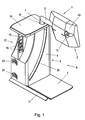
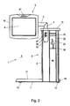
- a running as a game or entertainment device device 1 can be seen, which has a compact screen unit 2, which via a horizontal support arm 3 cantilevered with a vertical support column 4 is connected.
- the support column 4 is arranged vertically displaceable in a base 5, which is designed as a base housing 6, as will be explained in more detail below with reference to FIG. 4 in detail.
- the base housing 6 is intended for installation on the floor of a room, and on the bottom side extends away from the base housing 6, a bottom plate 7, which gives the device 1 in the installation with the laterally projecting screen unit 2 additional stability, since this bottom plate 7 on the same Side of the base housing 6 is like the screen unit 2.
- a bottom plate 7 which gives the device 1 in the installation with the laterally projecting screen unit 2 additional stability, since this bottom plate 7 on the same Side of the base housing 6 is like the screen unit 2.
- a sufficient free space 8 is given, so that a person, the device 1, easily in front of this device 1 (as shown in Fig. 5 or 6 on the right side thereof) on a chair, stool or the like. Seating or sitting on a wheelchair, nonetheless a direct, straight line of sight to the screen 9 of the screen unit 2 is given.
- the screen or the monitor unit 9 of the screen unit 2 is preferably designed as a touch screen monitor unit, so that a direct input on the screen 9 without Wegverrenkache or Kopfverschwenkungen in the case of a person sitting in front of the screen unit 2 person is possible.
- the screen unit 2 is secured by a lock 10 (see Fig. 1) on the support arm 3, but it can be easily removed from the arm 3 and unlock the lock 10 and simply mounted on the support arm 3 by sliding, and they are after assembly is secured by the lock 10.
- the pivotal mounting of the screen unit 2 on the support arm 3 will be explained in more detail below with reference to FIG. 7.
- the bottom plate 7 has at its rear longitudinal edge following the base housing 6 an angular edging as a footrest 11, see. Fig. 1 to 6. Furthermore, the bottom plate 7, if it is not intended to rest directly on the floor of the installation, be provided with support feet 12, which may be formed, for example, as glued plastic parts. These feet 12, cf. Fig. 2 to 4, the bottom plate 7 and the bottom of the base housing 6 at a distance from the ground hold, this distance is realized except by the feet 12 by rollers 13, on the opposite side, ie facing away from the bottom plate 7 side of the base housing 6 at its lower bottom edge 14 (s. Fig. 2 and 3) are arranged.
- rollers 13 Preferably, two such rollers 13, one each in a corner region 14 of the base housing 6, are arranged, and these rollers 13 enable a method of the device 1 on the ground with tilting of the base housing 6, as shown in Fig. 2 to the rollers 13th to the right, clockwise.
- the base housing 6 has at its top a table top 15, s. 1, which has a passage opening 16 for the passage of the support column 4 of the screen unit 2 under sealing (eg by means of an unspecified lip seal) and otherwise serves a storage area for documents or objects, such as glasses, ashtrays, books, to create written documents and the like.
- the table top 15 is at the back of the device 1 via there a taper 17 having socket housing 6, and below the table top 15 is obtained in the space obtained by the taper 17 a vertical plate or bar 18, for example, with illuminated Flexi design elements 19 is provided.
- an arcuate, illuminated design element 20 is provided on at least one side wall of the base housing 6.
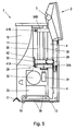
- the computer unit 22 is provided in the base housing 6 in view of the fact that the present apparatus 1 is equipped with its own intelligence for the purpose of realizing an amusement machine or game machine, as well as a money input unit 23 shown in FIGS. 2, 3 and 4, which also is designed in modular design and an entry slot 24 for banknotes and a coin insertion slot 25 and a coin return slot 26 in a conventional manner. Below this money input module 23 is also located in a conventional manner, a ticket 27, in which the thrown money is collected, see. Fig. 4.
- This drive unit 28 is embodied, for example, with a spindle drive 29, wherein a threaded spindle 30 is driven by a motor 31, possibly via a built-in motor housing, not shown in detail in the drawing gearbox.
- the motor 31 is designed as an electric motor, to which a power supply unit 32 with a transformer and / or switching power supply as well as a control 33 are assigned.
- the motor 31 is mounted on a base housing 6 within the modular drive unit 28 fixed lower bearing block 34 A, which is penetrated by the spindle 30 and rotatably supports.
- the spindle 30 is rotatably mounted in a further, upper bearing block 34 B, which is fixedly mounted in the base housing 6.
- the spindle 30 further passes through a threaded bore with a corresponding internal thread of a spindle nut block 35 which is fixedly connected to the supporting column 4 formed as a tube.
- the drive unit 28 includes a guide rod 36 for guiding the spindle nut block 35 and the support column 4 in the up and down movement.
- the motor 31 thus rotatably drives the spindle 30, and by the threaded engagement, the spindle nut block 35 is moved up or down along the rotating spindle 30.
- This vertical movement of the spindle nut block 35 is additionally guided by the guide rod 36.
- the spindle nut block 35 and the support column 4 moves up or down accordingly, so that the desired height adjustment of the screen unit 2 can be accomplished in a stable manner on the support column 4.
- the screen unit 2 from one in Figs. 1, 2 and 5 apparent bottom position can be adjusted by 30 cm in height upwards, the upper position in Fig. 3 and 6 is shown.
- buttons 37 and 38 are provided at the front of the base housing 6 in the upper region adjacent the space 8 for the seated person, said control buttons 37th , 38 are connected to the motor controller 33 via electrical lines not shown in detail in the drawing.
- the executed as a pipe hollow support column 4 takes in its interior cable 39 for the supply of the screen unit 2.
- the cables 39 extend from the vertical support column 4 then into the likewise formed as a tube horizontal support arm 3 and from there to corresponding terminals in the screen unit 2, said electrical connection with sufficiently movable cables per se may be conventional and therefore not closer in the drawing is shown.
- transponder system 40 At the front of the base housing 6 is further in the area below the control buttons 37, 38 still a transponder system 40, s. Figures 2, 3 and 4. This transponder system 40 is used to facilitate registration for various registered user services.
- the height adjustment drive unit 28 is fixed as an independent module in the base housing 6, for example by screwing.
- the electric or electromechanical drive unit 28 it is also easily possible to determine any jamming of the support column 4 by an overload detection or by motion sensors, in which case the drive is switched off and optionally an alarm device, in particular a flashing lamp or the like., Can be turned on.
- the monetary input unit 23 can have a wide variety of configurations or components as required, and the components can also be exchangeable. Possible input units are e.g. Coin validator, note reader, but also chip card reader, etc.
- the ticket 27 is preferably arranged so that it is separated by an additional lock from the technology area and can be removed separately.
- the vertical support column 4 and thus the screen unit 2 in the vertical direction preferably from the lowest point to eg 30 cm vertically upward are adjusted, wherein in the case of a spindle drive 29 as described or a comparable drive unit 28 a - preferably - infinitely variable Height adjustment is possible.
- the motor control 33 It is also conceivable to connect the motor control 33 with limit switches in order to automatically stop the support column 4 in the lower and upper positions.
- limit switches are schematically illustrated in Figs. 5 and 6 at 41A and 41B. These limit switches 41A, 41B act with a mounted on the spindle motor block 35 lateral switching element 42 together.
- the screen unit 2 itself with a housing 43, in which the touch screen monitor 9 is arranged, is arranged pivotable directly around the horizontal support arm 3, wherein, for example, a pivoting of the screen plane in the range of 10 ° to 65 ° with respect to a vertical plane 44, ( see the illustrations in Fig. 7 and 8) is conceivable.
- the device 1 offers the user in any position, whether sitting or standing, and the desired ease of use for any body size.
- the horizontal support arm 3 is mounted in bearing shells 45 of the screen unit 2, wherein a bearing block 46 provides an adjustable clamping in the sense of a sluggish mounting of the support arm 3 in the bearing shells 45.
- the force of the clamping by the bearing block 46 can be accomplished by clamping screws, not shown in Fig. 7, with which the bearing block 46 within the housing 43 as shown in Fig. 7 to the left, to the support arm 3, pulled.
- stops are provided, which come in pairs in the two end positions to each other to the plant and prevent further pivoting beyond the two end positions shown.
- the screen unit 2 may also include a webcam video camera 47 including illumination (see also FIG. 2, except FIG. 7) and furthermore only further schematically indicated in FIG. 7, such as a controller 48 and a speaker 49, included. It is also conceivable to provide a stereo loudspeaker arrangement, cf. also Fig. 4
Landscapes
- Engineering & Computer Science (AREA)
- General Engineering & Computer Science (AREA)
- Mechanical Engineering (AREA)
- Devices For Indicating Variable Information By Combining Individual Elements (AREA)
- Fittings On The Vehicle Exterior For Carrying Loads, And Devices For Holding Or Mounting Articles (AREA)
- Position Input By Displaying (AREA)
- Coin-Freed Apparatuses For Hiring Articles (AREA)
Applications Claiming Priority (1)
| Application Number | Priority Date | Filing Date | Title |
|---|---|---|---|
| AT0062205U AT8874U1 (de) | 2005-09-14 | 2005-09-14 | Vorrichtung zur informationswiedergabe, unterhaltung und/oder datenverarbeitung |
Publications (2)
| Publication Number | Publication Date |
|---|---|
| EP1764543A2 true EP1764543A2 (fr) | 2007-03-21 |
| EP1764543A3 EP1764543A3 (fr) | 2008-07-30 |
Family
ID=37192251
Family Applications (1)
| Application Number | Title | Priority Date | Filing Date |
|---|---|---|---|
| EP06450122A Withdrawn EP1764543A3 (fr) | 2005-09-14 | 2006-09-06 | Dispositif destiné à la reproduction de données |
Country Status (3)
| Country | Link |
|---|---|
| US (1) | US20080123265A1 (fr) |
| EP (1) | EP1764543A3 (fr) |
| AT (1) | AT8874U1 (fr) |
Cited By (1)
| Publication number | Priority date | Publication date | Assignee | Title |
|---|---|---|---|---|
| CN113944835A (zh) * | 2021-09-23 | 2022-01-18 | 张百盈 | 一种多范围多方位激光测绘系统 |
Families Citing this family (13)
| Publication number | Priority date | Publication date | Assignee | Title |
|---|---|---|---|---|
| JP4923121B2 (ja) * | 2010-02-25 | 2012-04-25 | 東芝テック株式会社 | ディスプレイ装置及びディスプレイ装置システム |
| EP2662747A1 (fr) * | 2012-05-09 | 2013-11-13 | Flytech Technology Co., Ltd | Dispositif dýaffichage de type horizontal |
| US9679435B2 (en) * | 2013-05-15 | 2017-06-13 | Incredible Technologies, Inc. | Gaming machine mounting apparatus and system for supporting an overhead display |
| CN104251370B (zh) * | 2013-06-28 | 2017-02-01 | 国网山东省电力公司德州供电公司 | 电子设备及其支架装置 |
| WO2017205409A1 (fr) * | 2016-05-23 | 2017-11-30 | Vantage Point Products Corp. | Montant |
| US11793959B2 (en) | 2018-03-16 | 2023-10-24 | Drägerwerk AG & Co. KGaA | Ventilator with adjustable user interface |
| US10506730B2 (en) * | 2018-04-13 | 2019-12-10 | Aristocrat Technologies Australia Pty Limited | Overhead display assembly and method for electronic gaming machines |
| CN111754903B (zh) * | 2020-07-17 | 2022-04-22 | 枣庄职业学院 | 一种智能视频人力资源看板系统及其使用方法 |
| CN111987076B (zh) * | 2020-08-31 | 2023-06-16 | 中国电子科技集团公司第四十四研究所 | 一种近红外光与可见光的宽光谱光电探测器及其制作方法 |
| CN113357500B (zh) * | 2021-06-28 | 2022-12-09 | 刘璐 | 一种英语混合式教学多语言显示屏幕 |
| CN113551121B (zh) * | 2021-06-29 | 2022-07-22 | 贵州乌江水电开发有限责任公司 | 一种高效的雷达调节装置 |
| CN114326270A (zh) * | 2021-12-11 | 2022-04-12 | 深圳市右转智能科技有限责任公司 | 一种小型会议室背景音乐安装装置 |
| CN117119734B (zh) * | 2023-10-20 | 2023-12-22 | 中铁合肥建筑市政工程设计研究院有限公司 | 一种基于bim的建筑施工管理设备 |
Family Cites Families (16)
| Publication number | Priority date | Publication date | Assignee | Title |
|---|---|---|---|---|
| US4625731A (en) * | 1984-10-10 | 1986-12-02 | Picker International, Inc. | Ultrasonic image display mounting |
| US4638969A (en) * | 1984-12-24 | 1987-01-27 | Milliken Research Corporation | Video display arrangement |
| DE3544900A1 (de) * | 1985-12-19 | 1987-06-25 | Minox Gmbh | Bewegbar montierte buehne fuer bildschirmgeraete, mikrofilmgeraete oder aehnliche geraete |
| DE3742959A1 (de) * | 1987-12-18 | 1989-06-29 | Mannesmann Kienzle Gmbh | Vorrichtung fuer die aufnahme der komponenten eines bildschirmarbeitsplatzes |
| US5398991A (en) * | 1993-02-09 | 1995-03-21 | Sony Trans Com Incorporated | Seat arm display monitor deployment mechanism |
| US5630566A (en) * | 1995-05-30 | 1997-05-20 | Case; Laura | Portable ergonomic work station |
| KR100242834B1 (ko) * | 1996-12-04 | 2000-02-01 | 윤종용 | Lcd 모니터 |
| US6098936A (en) * | 1998-02-23 | 2000-08-08 | Birrell; Andrew | Portable ergonomic work station |
| US6108195A (en) * | 1998-12-11 | 2000-08-22 | Inclose Design, Inc. | Computer system having thin-profile display with removable connector assembly |
| US6298794B1 (en) * | 1999-08-26 | 2001-10-09 | Microsphere Inc. | Ergonomic computer workstation |
| DE19943804A1 (de) * | 1999-09-13 | 2001-03-22 | Foco Cubus Verwaltungsgmbh | Computerständer |
| DE29923396U1 (de) * | 1999-10-25 | 2000-08-10 | Wilkhahn Wilkening + Hahne GmbH + Co., 31848 Bad Münder | Pult |
| AT412432B (de) * | 1999-12-22 | 2005-02-25 | Funworld Elektronik Ges M B H | Vorrichtung zur unterhaltung, informationswiedergabe oder datenverarbeitung |
| US6796536B1 (en) * | 2002-09-04 | 2004-09-28 | Ebsoo Media, Inc. | Computer support apparatus and method |
| US6655645B1 (en) * | 2002-12-31 | 2003-12-02 | Shin Zu Shing Co., Ltd. | Automatically adjusting support for an LCD monitor |
| KR100531313B1 (ko) * | 2004-03-15 | 2005-11-29 | 엘지전자 주식회사 | 영상표시장치용 스탠드 |
-
2005
- 2005-09-14 AT AT0062205U patent/AT8874U1/de not_active IP Right Cessation
-
2006
- 2006-09-06 EP EP06450122A patent/EP1764543A3/fr not_active Withdrawn
- 2006-09-12 US US11/519,456 patent/US20080123265A1/en not_active Abandoned
Cited By (1)
| Publication number | Priority date | Publication date | Assignee | Title |
|---|---|---|---|---|
| CN113944835A (zh) * | 2021-09-23 | 2022-01-18 | 张百盈 | 一种多范围多方位激光测绘系统 |
Also Published As
| Publication number | Publication date |
|---|---|
| US20080123265A1 (en) | 2008-05-29 |
| EP1764543A3 (fr) | 2008-07-30 |
| AT8874U1 (de) | 2007-01-15 |
Similar Documents
| Publication | Publication Date | Title |
|---|---|---|
| DE69012400T2 (de) | Elektronisches Informationsgerät. | |
| AT8874U1 (de) | Vorrichtung zur informationswiedergabe, unterhaltung und/oder datenverarbeitung | |
| DE102014104681B4 (de) | Operationstischsäule und Operationstisch mit einer derartigen Operationstischsäule | |
| EP2145564B1 (fr) | Bras de support pour un dispositif de projection | |
| DE202007010920U1 (de) | Präsentationssystem | |
| EP2997987A1 (fr) | Machine de dialyse | |
| DE102005054466B4 (de) | Vorrichtung zum Halten einer Aktivtafel | |
| EP1582457B1 (fr) | Siège de véhicule, en particulier siège pour passagers d'avion | |
| DE202010006908U1 (de) | Neuartiges TV-Board mit einer Anzahl von senkrecht ausfahrbaren TV-Halterungen | |
| DE10153492B4 (de) | Tisch, insbesondere Schülertisch | |
| DE10228341A1 (de) | Höhenverstellbare Trägerplatte für einen Bildschirm | |
| DE102011090045A1 (de) | Sitz-Unterhaltungssystem | |
| WO2006131084A1 (fr) | Dispositif de creation d'un evenement | |
| EP0629376A1 (fr) | Appareil mobile à rayons X | |
| DE3824187C2 (fr) | ||
| EP1464598B1 (fr) | Dispositif pour manipuler des panneaux | |
| DE60309089T2 (de) | Schieb- und drehbare Trägervorrichtung für eine Abgabevorrichtung | |
| DE202008004753U1 (de) | Halteeinrichtung für ein Tablett | |
| DE102009001713B4 (de) | Mobiliar mit beweglicher Abdeckplatte | |
| DE29820624U1 (de) | PC-Gehäuse | |
| DE102017122776B4 (de) | Betrachtungsvorrichtung, mit welcher sich ein Benutzer aus wählbaren Perspektiven betrachten kann | |
| DE10102032C2 (de) | Schuhreinigungsvorrichtung | |
| DE202009003003U1 (de) | Tischmöbel | |
| DE29615193U1 (de) | Fahrbarer Tablarträger | |
| DE102011005871B4 (de) | Haltevorrichtung für ein Anzeigemittel an einem münzbetätigten Unterhaltungsautomaten |
Legal Events
| Date | Code | Title | Description |
|---|---|---|---|
| PUAI | Public reference made under article 153(3) epc to a published international application that has entered the european phase |
Free format text: ORIGINAL CODE: 0009012 |
|
| AK | Designated contracting states |
Kind code of ref document: A2 Designated state(s): AT BE BG CH CY CZ DE DK EE ES FI FR GB GR HU IE IS IT LI LT LU LV MC NL PL PT RO SE SI SK TR |
|
| AX | Request for extension of the european patent |
Extension state: AL BA HR MK YU |
|
| PUAL | Search report despatched |
Free format text: ORIGINAL CODE: 0009013 |
|
| AK | Designated contracting states |
Kind code of ref document: A3 Designated state(s): AT BE BG CH CY CZ DE DK EE ES FI FR GB GR HU IE IS IT LI LT LU LV MC NL PL PT RO SE SI SK TR |
|
| AX | Request for extension of the european patent |
Extension state: AL BA HR MK RS |
|
| AKX | Designation fees paid | ||
| REG | Reference to a national code |
Ref country code: DE Ref legal event code: 8566 |
|
| STAA | Information on the status of an ep patent application or granted ep patent |
Free format text: STATUS: THE APPLICATION IS DEEMED TO BE WITHDRAWN |
|
| 18D | Application deemed to be withdrawn |
Effective date: 20090401 |