EP1764624A2 - Module de transmission-réception du système radar - Google Patents
Module de transmission-réception du système radar Download PDFInfo
- Publication number
- EP1764624A2 EP1764624A2 EP06016328A EP06016328A EP1764624A2 EP 1764624 A2 EP1764624 A2 EP 1764624A2 EP 06016328 A EP06016328 A EP 06016328A EP 06016328 A EP06016328 A EP 06016328A EP 1764624 A2 EP1764624 A2 EP 1764624A2
- Authority
- EP
- European Patent Office
- Prior art keywords
- terminal
- switch
- transmitting
- signal
- receiving
- Prior art date
- Legal status (The legal status is an assumption and is not a legal conclusion. Google has not performed a legal analysis and makes no representation as to the accuracy of the status listed.)
- Granted
Links
Images


Classifications
-
- G—PHYSICS
- G01—MEASURING; TESTING
- G01S—RADIO DIRECTION-FINDING; RADIO NAVIGATION; DETERMINING DISTANCE OR VELOCITY BY USE OF RADIO WAVES; LOCATING OR PRESENCE-DETECTING BY USE OF THE REFLECTION OR RERADIATION OF RADIO WAVES; ANALOGOUS ARRANGEMENTS USING OTHER WAVES
- G01S7/00—Details of systems according to groups G01S13/00, G01S15/00, G01S17/00
- G01S7/02—Details of systems according to groups G01S13/00, G01S15/00, G01S17/00 of systems according to group G01S13/00
- G01S7/03—Details of HF subsystems specially adapted therefor, e.g. common to transmitter and receiver
- G01S7/034—Duplexers
Definitions
- the present invention relates to a radar system, and especially relates to a construction of a receiving system of a transmitting-receiving module used for radar system.
- radar system objects in the transmission direction of radio wave are detected by transmitting radio wave and receiving the reflected wave.
- a phased array radar system which detects objects in a predetermined range by changing the transmitting and receiving direction by changing phases of transmitting and receiving radio wave, is known.
- the transmitting-receiving module used in the phased array radar system had a circuit configuration, for example, shown in Fig. 1. Namely, an antenna 1 for transmitting and receiving is connected with an A terminal of a three terminal circulator 2, an output of transmitting system power amplifier 3 is connected with a C terminal of the circulator 2, an A terminal of an RF switch 4 is connected with a B terminal of the circulator 2. And, a B terminal of the RF switch 4 is connected with an A terminal of an RF switch 5, a C terminal is connected with a terminating resistance 6 respectively.
- a B terminal of the RF switch 5 is connected with a B terminal of an RF switch 7, a C terminal with a fixed attenuator 8 respectively, another terminal of the fixed attenuator 8 is connected with a C terminal of the RF switch 7.
- an A terminal of the RF switch 7 is connected with an input of a low noise amplifier 9, signal amplified by the low noise amplifier 9 is signal processed for example so as to be visual displayed in normal receiving circuit 10.
- Operation of a conventional transmitting-receiving module having a circuit configuration mentioned above is as follows. First, when in transmission, by connecting all of the RF switches 4, 5, 7 with C terminal side, reflected wave from antenna to the low noise amplifier 9 is minimized to prevent the low noise amplifier 9 from destruction.
- the receiving circuit 10 detects it, and prevents saturation of the low noise amplifier 9 by connecting the RF switch 4 with B terminal side, the RF switch 5, 7 with C terminal side.
- the present invention was performed to overcome the problem that in the conventional transmitting-receiving module mentioned above uses three RF switches to cause degradation of noise figure in receiving system owing to the insertion loss of three RF switches.
- the present invention aims to supply a transmitting-receiving module capable of improving the noise figure while maintaining the function of the receiving system of the transmitting-receiving module, and further, make it possible to miniaturize the circuit itself.
- a transmitting-receiving module of a radar system including a transmitting circuit which supplies transmitting RF signal, a three terminal circulator having three terminals, a first terminal is connected with a transmitting and receiving antenna which outputs transmitting RF signal which is outputted from the transmitting circuit and receives receiving RF signal which is a reflectedwave of the transmitting RF signal, signal received by the transmitting and receiving antenna is outputted to a second terminal, outputting to a third terminal the signal inputted to the second terminal, a first RF switch which is connected with the second terminal of the three terminal circulator and the output of which can be switched over, a second RF switch the input of which can be switched over, an attenuator connected between the first RF switch and the second switch, a receiving circuit connected with the output of the second RF switch, when transmitting a radar signal, the first RF switch is connected with the attenuator, the second RF switch is not connected with the attenuator, when receiving a radar signal,
- a transmitting-receivingmodule of a radar system which can improve the noise figure while maintaining the function of a receiving system of a transmitting-receiving module, at the same time make it possible to miniaturize the circuit itself, can be obtained.
- FIG. 2 An example of a circuit configuration of a transmitting-receiving module according to a first embodiment of the present invention is shown in Fig. 2.
- the transmitting-receiving module is composed of a three terminal circulator 22 connected with a transmitting-receiving antenna 21, a transmitting system power amplifier 23, a 1-input 2-output RF switch 25, a 2-input 1-output RF switch 27, a fixed attenuator 28, a low noise amplifier 29, and a receiving circuit 30.
- B terminal, which is one output terminal of the RF switch 25, is connected with B terminal which is one input terminal of RF switch 27, while, C terminal which is another output terminal of RF switch 25, is connected with one terminal of the fixed attenuator 28, another terminal of the fixed attenuator 28 is connected with C terminal which is another input terminal of the RF switch 27.
- the three terminal circulator 22 has A terminal, B terminal, and C terminal, the operation is as follows; signal inputted in A terminal is outputted from B terminal, signal inputted in B terminal is outputted from C terminal, signal inputted in C terminal is outputted from A terminal.
- the transmitting-receiving antenna 21 is connected with A terminal (first terminal) of the three terminal circulator 22, C terminal (third terminal) of the three terminal circulator 22 is connected with an output terminal of the transmitting series power amplifier 23, B terminal (second terminal) of the circulator 22 is connected with A terminal which is an input terminal of the RF switch 25.
- the output terminal of the RF switch 25 is connected with C terminal side
- the input terminal of the RF switch 27 is connected with B terminal side.
- undesired reflection component in antenna generated when transmitted from the transmitting-receiving antenna 21 is outputted from B terminal of the three terminal circulator 22, enters into the fixed attenuator 28 from A terminal of the RF switch 25 through C terminal, and is consumed here and is attenuated.
- Undesired RF component which is not attenuated in the fixed attenuator 28 is transmitted to C terminal of the RF switch 27, here, because the C terminal is not connected with A terminal, it is reflected here, returns to the fixed attenuator 28 and is attenuated here again. Therefore, the fixed attenuator 28 attenuates the undesired reflection component of transmitted time twice.
- the fixed attenuator 28 has an attenuation amount of-10dB and an impedance of 50Q. In this situation, undesired reflection signal is attenuated by 10dB while being transmitted from the RF switch 25 to the RF switch 27, and is further attenuated by 10dB when reflected at C terminal of the RF switch 27.
- the undesired reflection signal is attenuated only once by the fixed attenuator 8. Therefore, the attenuation amount of the fixed attenuator is needed to be about 20dB in order to attenuate the input of the low noise amplifier to a comparable level.
- receiving signal received by the transmitting-receiving antenna 21 is inputted from A terminal of the three terminal circulator 22 and outputted from B terminal, receiving RF signal is sent to RF switch25.
- the output terminal of the RF switch 25 is connected with B terminal side, the input terminal of the RF switch 25 is connected with B terminal side.
- RF signal received by the transmitting-receiving antenna 21 is inputted from A terminal of the three terminal circulator 22 and outputted from B terminal, and is sent to the low noise amplifier 29 through B terminal which is an output terminal of RF switch 25, through B terminal of the RF switch 27.
- Receiving RF signal amplified by the low noise amplifier 29 is inputted to the receiving circuit 30, and is signal processed in receiving circuit 30 for example for visual display.
- the receiving circuit 30 detects it and controls the RF switches 25, 27. Namely, output terminal of the RF switch 25 is connected with C terminal side, input terminal of the RF switch 27 is connected with C terminal side.
- receiving RF signal enters into the fixed attenuator 28 from RF switch 25, and is attenuated, is outputted from A terminal of RF switch 27, is inputted in the receiving circuit 30 through the low noise amplifier 29.
- signal processed by the receiving circuit 30 is amplified by the low noise amplifier 29 arranged on the previous step, however, there is scarcely no problem if attenuation in the fixed attenuator 28 is enough.
- the transmitting-receiving module can decrease the number of RF switch which lies between the circulator 22 and the low noise amplifier 29 to two with maintaining receiving system function.
- the decrease of RF switch contributes greatly to improvement of noise figure, besides it makes possible of miniaturizing the whole circuit because one RF switch and terminating resistance become unnecessary compared with the conventional one.
- loss of receiving system can be improved by 0.5dB by eliminating one RF switch, assuming loss of an RF switch is 0.5dB.
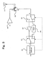
- FIG. 3 An example of a circuit configuration of a transmitting-receiving module according to a second embodiment of the present invention is shown in Fig. 3.
- the transmitting-receiving module is composed of a three terminal circulator 32 connected with a transmitting-receiving antenna 31, a transmitting system power amplifier 33 included in transmitting circuit, 1-input 2-output RF switch 35, a fixed attenuator 38, a low noise amplifier 39, and a receiving circuit 40.
- B terminal which is one output terminal of the RF switch 35, is connected with an input terminal of the low noise amplifier 39, while, C terminal, which is another output terminal of that is connected with one end of the fixed attenuator 38.
- Output terminal of the low noise amplifier 39 is connected with B terminal which is one input terminal of RF switch 37, another terminal of the fixed attenuator 38 is connected with C terminal which is another input terminal of RF switch 37.
- the three terminal circulator 32 is provided with A terminal, B terminal, and C terminal, and the operation is as follows; signal inputted into A terminal is outputted from B terminal, signal inputted into B terminal is outputted from C terminal, signal inputted into C terminal is outputted from A terminal.
- the transmitting-receiving antenna 31 is connected with A terminal (first terminal) of the three terminal circulator 32, C terminal (third terminal) of the three terminal circulator 32 is connected with an output terminal of the transmitting series power amplifier 33, B terminal (second terminal) of the circulator 32 is connected with A terminal of the RF switch 35.
- transmitting- receiving module When transmitting radar signal, output of transmitting system power amplifier 33 included in transmitting circuit is inputted into the three terminal circulator 32 and is outputted from A terminal, and transmitting RF signal is transmitted from the antenna 31. Receiving signal received by antenna 31 is inputted into A terminal of the three terminal circulator 32 and is outputted from B terminal, receiving RF signal is sent to RF switch 35. When radar signal is being transmitted, output terminal of RF switch 35 is connected with C terminal side, input terminal of RF switch 37 is connected with B terminal side.
- the fixed attenuator has, for example, an attenuation of -10dB and an impedance of 50 ⁇ .
- unwanted reflected signal attenuates by 10dB while traveling from RF switch 35 to RF switch 37, and further attenuates by 10dB when reflected by C terminal of RF switch 37. In this way, destruction is prevented by attenuating unwanted reflected component entering into the low noise amplifier 39.
- the receiving circuit 40 detects it and controls the RF switches 35, 37. If an excessively large receiving signal enters in A terminal of the three terminal circulator 32 while receiving radar signal, amplifying the receiving signal with the low noise amplifier 39 is not necessary. Therefore, output terminal of RF switch 35 is connected with C terminal side, and input terminal of RF switch 37 is connected with C terminal side. By this situation, receiving RF signal enters into the fixed attenuator 38 from RF switch 35, and is attenuated, is outputted from A terminal of RF switch 37, is inputted in the receiving circuit, without going through the low noise amplifier 39. Therefore, saturation of the low noise amplifier 39 can be fully prevented.
- the transmitting-receiving module can decrease the number of RF switch 35 which lies between the circulator 32 and the low noise amplifier 39 to only one with maintaining receiving system function. Therefore, assuming the loss of the RF switch is 0.5dB, the loss in receiving system can be improved by about 1dB by eliminating two RF switches.
- the decrease of RF switch contributes greatly to improvement of noise figure, besides it makes possible of miniaturizing the whole circuit because one RF switch and terminating resistance become unnecessary compared with the conventional one.
- the present invention is not limited to the above-mentioned embodiment, but can be used with a variety of modifications within the scope of the technical thoughts.
Landscapes
- Engineering & Computer Science (AREA)
- Computer Networks & Wireless Communication (AREA)
- Physics & Mathematics (AREA)
- General Physics & Mathematics (AREA)
- Radar, Positioning & Navigation (AREA)
- Remote Sensing (AREA)
- Radar Systems Or Details Thereof (AREA)
- Transceivers (AREA)
- Input Circuits Of Receivers And Coupling Of Receivers And Audio Equipment (AREA)
Applications Claiming Priority (1)
| Application Number | Priority Date | Filing Date | Title |
|---|---|---|---|
| JP2005259687A JP4509899B2 (ja) | 2005-09-07 | 2005-09-07 | 送受信モジュール |
Publications (3)
| Publication Number | Publication Date |
|---|---|
| EP1764624A2 true EP1764624A2 (fr) | 2007-03-21 |
| EP1764624A3 EP1764624A3 (fr) | 2010-07-14 |
| EP1764624B1 EP1764624B1 (fr) | 2012-10-31 |
Family
ID=37529261
Family Applications (1)
| Application Number | Title | Priority Date | Filing Date |
|---|---|---|---|
| EP06016328A Active EP1764624B1 (fr) | 2005-09-07 | 2006-08-04 | Module de transmission-réception du système radar |
Country Status (3)
| Country | Link |
|---|---|
| US (1) | US7436353B2 (fr) |
| EP (1) | EP1764624B1 (fr) |
| JP (1) | JP4509899B2 (fr) |
Cited By (1)
| Publication number | Priority date | Publication date | Assignee | Title |
|---|---|---|---|---|
| CN112087243A (zh) * | 2019-06-14 | 2020-12-15 | 海能达通信股份有限公司 | 一种信号转发装置 |
Families Citing this family (8)
| Publication number | Priority date | Publication date | Assignee | Title |
|---|---|---|---|---|
| US20090096586A1 (en) * | 2007-10-12 | 2009-04-16 | Icontrol, Inc. | Radiofrequency Tracking and Communication Device and Method for Operating the Same |
| JP2009267943A (ja) * | 2008-04-28 | 2009-11-12 | Toshiba Corp | 鉄道車両用伝送装置及び鉄道車両用伝送システム |
| EP2346175B1 (fr) * | 2010-01-15 | 2015-03-11 | Telefonaktiebolaget L M Ericsson | Procédé et dispositifs de transmission pour configurer un amplificateur de puissance multisupport |
| CN103812463A (zh) * | 2014-01-13 | 2014-05-21 | 智坤(江苏)半导体有限公司 | 射频功率放大器的增益控制方法 |
| JP6649217B2 (ja) * | 2016-09-20 | 2020-02-19 | 株式会社東芝 | 受信信号増幅器及び送受信装置 |
| CN110932751B (zh) * | 2019-11-26 | 2025-02-07 | 京信网络系统股份有限公司 | 大功率上下行切换装置和通信设备 |
| CN113904631A (zh) * | 2021-10-13 | 2022-01-07 | 西安博瑞集信电子科技有限公司 | 低噪声放大器及低噪声放大器芯片 |
| CN116032311A (zh) * | 2022-12-21 | 2023-04-28 | 维沃移动通信有限公司 | 干扰消除电路及方法 |
Citations (2)
| Publication number | Priority date | Publication date | Assignee | Title |
|---|---|---|---|---|
| JPH0972955A (ja) | 1995-09-05 | 1997-03-18 | Mitsubishi Electric Corp | レーダ受信機 |
| JP2005259687A (ja) | 2004-02-13 | 2005-09-22 | Kochi Univ | 色変換フィルタおよびそれを用いた有機elディスプレイ |
Family Cites Families (15)
| Publication number | Priority date | Publication date | Assignee | Title |
|---|---|---|---|---|
| US2935743A (en) * | 1956-06-04 | 1960-05-03 | Marconi Co Canada | Noise reduction in continuous wave doppler radar systems |
| US3761924A (en) * | 1972-09-14 | 1973-09-25 | Us Army | Isolimiter |
| US4725842A (en) * | 1982-09-27 | 1988-02-16 | Teledyne Industries, Inc. | Isolation apparatus for a continuous-wave radar system |
| US4792805A (en) * | 1987-04-28 | 1988-12-20 | Hughes Aircraft Company | Multifunction active array |
| US5008631A (en) * | 1989-08-16 | 1991-04-16 | Hewlett-Packard Company | Pulse analyzer with gain compression |
| DE9113444U1 (de) * | 1991-10-29 | 1992-01-09 | Siemens AG, 80333 München | Sende/Empfangs-Modul für eine elektronisch phasengesteuerte Antenne |
| DE4203932A1 (de) * | 1992-02-11 | 1993-08-12 | Deutsche Aerospace | Sende-/empfangsmodul |
| US5722063A (en) * | 1994-12-16 | 1998-02-24 | Qualcomm Incorporated | Method and apparatus for increasing receiver immunity to interference |
| JPH08298404A (ja) * | 1995-04-27 | 1996-11-12 | Murata Mfg Co Ltd | 送受信装置 |
| US5554865A (en) * | 1995-06-07 | 1996-09-10 | Hughes Aircraft Company | Integrated transmit/receive switch/low noise amplifier with dissimilar semiconductor devices |
| JP3309271B2 (ja) * | 1996-07-09 | 2002-07-29 | 京セラ株式会社 | 携帯端末 |
| US6127886A (en) * | 1997-10-30 | 2000-10-03 | The Whitaker Corporation | Switched amplifying device |
| JP2002335187A (ja) * | 2001-05-10 | 2002-11-22 | Matsushita Electric Ind Co Ltd | 無線通信機 |
| JP4141797B2 (ja) | 2002-10-31 | 2008-08-27 | 株式会社東芝 | 低反射型リミタ並びに低反射型リミタを用いた送受信モジュールおよびアクティブフェーズドアレーアンテナ |
| JP3875244B2 (ja) * | 2003-09-30 | 2007-01-31 | シャープ株式会社 | 無線通信用回路、無線通信装置、無線通信システム |
-
2005
- 2005-09-07 JP JP2005259687A patent/JP4509899B2/ja not_active Expired - Fee Related
-
2006
- 2006-08-04 EP EP06016328A patent/EP1764624B1/fr active Active
- 2006-08-25 US US11/509,765 patent/US7436353B2/en active Active
Patent Citations (2)
| Publication number | Priority date | Publication date | Assignee | Title |
|---|---|---|---|---|
| JPH0972955A (ja) | 1995-09-05 | 1997-03-18 | Mitsubishi Electric Corp | レーダ受信機 |
| JP2005259687A (ja) | 2004-02-13 | 2005-09-22 | Kochi Univ | 色変換フィルタおよびそれを用いた有機elディスプレイ |
Cited By (2)
| Publication number | Priority date | Publication date | Assignee | Title |
|---|---|---|---|---|
| CN112087243A (zh) * | 2019-06-14 | 2020-12-15 | 海能达通信股份有限公司 | 一种信号转发装置 |
| CN112087243B (zh) * | 2019-06-14 | 2022-05-17 | 海能达通信股份有限公司 | 一种信号转发装置 |
Also Published As
| Publication number | Publication date |
|---|---|
| JP2007074420A (ja) | 2007-03-22 |
| EP1764624A3 (fr) | 2010-07-14 |
| US7436353B2 (en) | 2008-10-14 |
| JP4509899B2 (ja) | 2010-07-21 |
| EP1764624B1 (fr) | 2012-10-31 |
| US20070115170A1 (en) | 2007-05-24 |
Similar Documents
| Publication | Publication Date | Title |
|---|---|---|
| US7889121B2 (en) | Transmit/receive module | |
| JP4962298B2 (ja) | 送受信機 | |
| US7688765B2 (en) | TDD switch of TDD wireless communication system | |
| US7436353B2 (en) | Transmitting-receiving module of radar system | |
| US20040264392A1 (en) | Time division multiplexing connection transceiver and its receiving automatic gain control method | |
| US20040242166A1 (en) | Low reflection limiter and transmitting/receiving module utilizing same | |
| CN110492951B (zh) | 一种射频反馈检测电路、天线组件以及电子设备 | |
| EP1707981A2 (fr) | Module émetteur-récepteur | |
| CN106160764A (zh) | 一种模块化微波组件的sc频段接收模块 | |
| JP5300057B2 (ja) | 送受信機 | |
| CN111323758B (zh) | 一种雷达与对抗双模双工的多功能变频组件 | |
| KR100743425B1 (ko) | 시분할복신 무선통신시스템의 고주파 전단 장치 | |
| JP2001228240A (ja) | Fmcwレーダの受信信号増幅装置 | |
| EP4082110B1 (fr) | Atténuateur absorbant à phase invariante | |
| KR102638396B1 (ko) | 신호의 송수신을 위한 공통 경로를 가진 송수신 모듈 | |
| US12627281B2 (en) | Multi-level digital step attenuator and digital step attenuation device | |
| CN218352479U (zh) | 一种高隔离度微波开关放大组件 | |
| KR20060088255A (ko) | 시분할 듀플렉스 시스템의 rf 송수신기 | |
| JP2024146138A (ja) | マイクロ波送受信モジュールおよびマイクロ波送信モジュール | |
| EP1538758A1 (fr) | Appareil radio | |
| KR100383612B1 (ko) | 이동 통신 단말의 송신 장치 | |
| JP2020085491A (ja) | アクティブ反射制御モジュールおよびアレイアンテナ | |
| CN117155317A (zh) | 一种连续波时钟功率放大系统和方法 | |
| JP2008258948A (ja) | 送受信モジュール | |
| CN120811418A (zh) | 一种小型化高可靠性大功率收发组件 |
Legal Events
| Date | Code | Title | Description |
|---|---|---|---|
| PUAI | Public reference made under article 153(3) epc to a published international application that has entered the european phase |
Free format text: ORIGINAL CODE: 0009012 |
|
| 17P | Request for examination filed |
Effective date: 20060804 |
|
| AK | Designated contracting states |
Kind code of ref document: A2 Designated state(s): AT BE BG CH CY CZ DE DK EE ES FI FR GB GR HU IE IS IT LI LT LU LV MC NL PL PT RO SE SI SK TR |
|
| AX | Request for extension of the european patent |
Extension state: AL BA HR MK YU |
|
| PUAL | Search report despatched |
Free format text: ORIGINAL CODE: 0009013 |
|
| AK | Designated contracting states |
Kind code of ref document: A3 Designated state(s): AT BE BG CH CY CZ DE DK EE ES FI FR GB GR HU IE IS IT LI LT LU LV MC NL PL PT RO SE SI SK TR |
|
| AX | Request for extension of the european patent |
Extension state: AL BA HR MK RS |
|
| RIC1 | Information provided on ipc code assigned before grant |
Ipc: H03G 3/20 20060101ALI20100609BHEP Ipc: H03F 3/72 20060101ALI20100609BHEP Ipc: H04B 1/48 20060101ALI20100609BHEP Ipc: H04B 1/44 20060101ALI20100609BHEP Ipc: G01S 7/35 20060101ALI20100609BHEP Ipc: G01S 7/03 20060101AFI20061221BHEP |
|
| AKX | Designation fees paid |
Designated state(s): DE FR GB |
|
| 17Q | First examination report despatched |
Effective date: 20111230 |
|
| GRAP | Despatch of communication of intention to grant a patent |
Free format text: ORIGINAL CODE: EPIDOSNIGR1 |
|
| GRAS | Grant fee paid |
Free format text: ORIGINAL CODE: EPIDOSNIGR3 |
|
| GRAA | (expected) grant |
Free format text: ORIGINAL CODE: 0009210 |
|
| AK | Designated contracting states |
Kind code of ref document: B1 Designated state(s): DE FR GB |
|
| REG | Reference to a national code |
Ref country code: GB Ref legal event code: FG4D |
|
| REG | Reference to a national code |
Ref country code: DE Ref legal event code: R096 Ref document number: 602006032740 Country of ref document: DE Effective date: 20121227 |
|
| PLBE | No opposition filed within time limit |
Free format text: ORIGINAL CODE: 0009261 |
|
| STAA | Information on the status of an ep patent application or granted ep patent |
Free format text: STATUS: NO OPPOSITION FILED WITHIN TIME LIMIT |
|
| 26N | No opposition filed |
Effective date: 20130801 |
|
| REG | Reference to a national code |
Ref country code: DE Ref legal event code: R097 Ref document number: 602006032740 Country of ref document: DE Effective date: 20130801 |
|
| REG | Reference to a national code |
Ref country code: FR Ref legal event code: PLFP Year of fee payment: 10 |
|
| REG | Reference to a national code |
Ref country code: FR Ref legal event code: PLFP Year of fee payment: 11 |
|
| REG | Reference to a national code |
Ref country code: FR Ref legal event code: PLFP Year of fee payment: 12 |
|
| REG | Reference to a national code |
Ref country code: FR Ref legal event code: PLFP Year of fee payment: 13 |
|
| PGFP | Annual fee paid to national office [announced via postgrant information from national office to epo] |
Ref country code: GB Payment date: 20240613 Year of fee payment: 19 |
|
| PGFP | Annual fee paid to national office [announced via postgrant information from national office to epo] |
Ref country code: FR Payment date: 20240611 Year of fee payment: 19 |
|
| PGFP | Annual fee paid to national office [announced via postgrant information from national office to epo] |
Ref country code: DE Payment date: 20240612 Year of fee payment: 19 |
|
| REG | Reference to a national code |
Ref country code: DE Ref legal event code: R119 Ref document number: 602006032740 Country of ref document: DE |
|
| GBPC | Gb: european patent ceased through non-payment of renewal fee |
Effective date: 20250804 |