EP1764877B1 - Connecteur , pièce complémentaire et dispositif de connexion - Google Patents
Connecteur , pièce complémentaire et dispositif de connexion Download PDFInfo
- Publication number
- EP1764877B1 EP1764877B1 EP06019104A EP06019104A EP1764877B1 EP 1764877 B1 EP1764877 B1 EP 1764877B1 EP 06019104 A EP06019104 A EP 06019104A EP 06019104 A EP06019104 A EP 06019104A EP 1764877 B1 EP1764877 B1 EP 1764877B1
- Authority
- EP
- European Patent Office
- Prior art keywords
- receptacle
- connector
- housing
- mating
- preventing portions
- Prior art date
- Legal status (The legal status is an assumption and is not a legal conclusion. Google has not performed a legal analysis and makes no representation as to the accuracy of the status listed.)
- Expired - Fee Related
Links
- 230000013011 mating Effects 0.000 title claims description 59
- 230000037431 insertion Effects 0.000 description 5
- 238000003780 insertion Methods 0.000 description 5
- 239000000463 material Substances 0.000 description 4
- 238000007789 sealing Methods 0.000 description 4
- 229920001971 elastomer Polymers 0.000 description 3
- 239000005060 rubber Substances 0.000 description 3
- 229920003002 synthetic resin Polymers 0.000 description 3
- 239000000057 synthetic resin Substances 0.000 description 3
- 239000002184 metal Substances 0.000 description 2
- 230000001419 dependent effect Effects 0.000 description 1
- 239000012530 fluid Substances 0.000 description 1
- 239000012858 resilient material Substances 0.000 description 1
- 230000000717 retained effect Effects 0.000 description 1
- 229920003051 synthetic elastomer Polymers 0.000 description 1
- 239000005061 synthetic rubber Substances 0.000 description 1
- XLYOFNOQVPJJNP-UHFFFAOYSA-N water Substances O XLYOFNOQVPJJNP-UHFFFAOYSA-N 0.000 description 1
Images


Classifications
-
- H—ELECTRICITY
- H01—ELECTRIC ELEMENTS
- H01R—ELECTRICALLY-CONDUCTIVE CONNECTIONS; STRUCTURAL ASSOCIATIONS OF A PLURALITY OF MUTUALLY-INSULATED ELECTRICAL CONNECTING ELEMENTS; COUPLING DEVICES; CURRENT COLLECTORS
- H01R13/00—Details of coupling devices of the kinds covered by groups H01R12/70 or H01R24/00 - H01R33/00
- H01R13/46—Bases; Cases
- H01R13/52—Dustproof, splashproof, drip-proof, waterproof, or flameproof cases
- H01R13/5219—Sealing means between coupling parts, e.g. interfacial seal
-
- H—ELECTRICITY
- H01—ELECTRIC ELEMENTS
- H01R—ELECTRICALLY-CONDUCTIVE CONNECTIONS; STRUCTURAL ASSOCIATIONS OF A PLURALITY OF MUTUALLY-INSULATED ELECTRICAL CONNECTING ELEMENTS; COUPLING DEVICES; CURRENT COLLECTORS
- H01R13/00—Details of coupling devices of the kinds covered by groups H01R12/70 or H01R24/00 - H01R33/00
- H01R13/40—Securing contact members in or to a base or case; Insulating of contact members
- H01R13/42—Securing in a demountable manner
- H01R13/436—Securing a plurality of contact members by one locking piece or operation
- H01R13/4364—Insertion of locking piece from the front
-
- H—ELECTRICITY
- H01—ELECTRIC ELEMENTS
- H01R—ELECTRICALLY-CONDUCTIVE CONNECTIONS; STRUCTURAL ASSOCIATIONS OF A PLURALITY OF MUTUALLY-INSULATED ELECTRICAL CONNECTING ELEMENTS; COUPLING DEVICES; CURRENT COLLECTORS
- H01R13/00—Details of coupling devices of the kinds covered by groups H01R12/70 or H01R24/00 - H01R33/00
- H01R13/62—Means for facilitating engagement or disengagement of coupling parts or for holding them in engagement
- H01R13/627—Snap or like fastening
- H01R13/6271—Latching means integral with the housing
- H01R13/6272—Latching means integral with the housing comprising a single latching arm
Definitions
- the present invention relates to a connector, to a mating connector and to a connector device provided with a pair of connectors engageable with each other.
- Some of connector devices each provided with a pair of connectors engageable with each other are constructed such that a watertight sealing member is mounted in one connector housing, and is resiliently held between the one connector housing and a mating connector to be engaged with the one connector housing, thereby preventing both connectors from shaking (see, for example, Japanese Examined Patent Publication No. H05-50113 ).
- the present invention was developed in view of the above problem and an object thereof is to provide an improved shake preventing function between a connector and a mating connector at the time of engagement.
- a connector comprising:
- a mating connector comprising:
- the first shake preventing portions are held in contact with the (mating) housing at or near the back side of the receptacle and the second shake preventing portions are held in contact with the (mating) housing at or near the opening side of the receptacle, thereby reducing the shaking between the housing and mating housing substantially in radial directions, and further the leading end of the receptacle is resiliently engaged with the mating connector, thereby reducing the shaking between the two housings substantially in the connecting directions of the two housings.
- the shaking between the connector and mating connector preferably substantially in three dimensional directions can be reduced, and no shaking occurs even if an excessive load is exerted in a radial direction between both housing since the first and second shake preventing portions, which are parts of the housing, are not deformed.
- the leading end of the receptacle is resiliently engageable with the mating connector, thereby reducing the shaking between the housing and the mating housing substantially in connecting directions of the two housings.
- the engaging portion includes a terminal holding portion at least partly insertable into the receptacle and/or a covering portion fittable on the outer circumferential surface of the receptacle.
- first shake preventing portions or the second shake preventing portions are located between the inner circumferential surface of the receptacle and the terminal holding portion and the others are located between the outer circumferential surface of the receptacle and the covering portion.
- a waterproof seal is to mounted on or to the mating housing and a leading end of the receptacle presses a flexible flange portion of the waterproof seal preferably substantially backward to be resiliently engaged therewith, thereby reducing the shaking between the housing and mating housing substantially in the connecting directions preferably in addition to displaying a water-entrance preventing function of the waterproof seal.
- an outer diameter of the engaging portion including the first shake preventing portions is slightly larger than the inner diameter of the back side of the receptacle, whereby the engaging portion preferably is at least partly insertable into the receptacle while being slightly squeezed.
- an inner diameter of the engaging portion including the second shake preventing portions is smaller than the outer diameter of the receptacle, whereby the receptacle preferably is slightly squeezed by the engaging portion when the engaging portion is at least partly fitted on or to the receptacle.
- first shake preventing portions and/or the second shake preventing portions are circumferentially arranged at substantially even intervals.
- a connector device comprising a connector according to the invention or a preferred embodiment thereof and a mating connector according to the invention or a preferred embodiment thereof.
- a connector device comprising:
- the first shake preventing portions are held in contact with the mating housing at the back side of the receptacle and the second shake preventing portions are held in contact with the mating housing at the opening side of the receptacle, thereby reducing the shaking between the male and female housings in radial directions, and further the leading end of the receptacle is resiliently engaged with the female connector, thereby reducing the shaking between the male and female housings in the connecting directions of the two housings.
- the shaking between the male and female connectors in three dimensional directions can be reduced, and no shaking occurs even if an excessive load is exerted in a radial direction between both housing since the first and second shake preventing portions, which are parts of the housing, are not deformed.
- the engaging portion includes a terminal holding portion insertable into the receptacle and a covering portion fittable on the outer circumferential surface of the receptacle, and either the first shake preventing portions or the second shake preventing portions are located between the inner circumferential surface of the receptacle and the terminal holding portion and the others are located between the outer circumferential surface of the receptacle and the covering portion.
- the engaging portion includes the terminal holding portion insertable into the receptacle and the covering portion fittable on the outer circumferential surface of the receptacle.
- FIG. 1 a mating side (right side in FIG. 1 ) is the front side of male connector 1 and a mating side (left side in FIG. 1 ) is the front side of a female connector 4.
- Radial directions of the connectors 1, 4 in the following description are upward, downward, leftward and rightward directions or oblique directions with respect to a terminal holding portion 51 in FIG. 5 .
- a connector device according to this embodiment is provided with or comprises the male connector 1 and the female connector 4.
- the male connector 1 includes a male housing 2 and one or more male terminals 3.
- the male housing 2 is integrally or unitarily made e.g.
- a tubular receptacle 21 having an open front side extends substantially in forward and backward directions FBD (preferably substantially parallel to a connecting direction CD of the two connectors 1, 4), and a terminal mounting portion 22 is formed behind the receptacle 21.
- the inner circumferential surface of the receptacle 21 preferably is substantially widened at an opening side as compared to a back side, thereby having a stepped or conical or diverging configuration.
- a lock portion 21 a engageable with a lock piece 53 (to be described later) of the female housing 5 projects outward (preferably substantially upward) at a lateral (preferably substantially upper) part of the outer circumferential surface of the receptacle 21 (see FIG. 1 ).
- Each male terminal 3 is integrally or unitarily formed preferably by press-working an electrically conductive (preferably metal) plate and at least partly is pressed or inserted into a terminal hole (not shown) formed in the terminal mounting portion 22 from an inserting side, preferably substantially from front.
- the male terminals 3 are so at least partly mounted in the male housing 2 as to be at least partly surrounded by the receptacle 21 and extend substantially in forward and backward directions FBD in the receptacle 21.
- the female connector 4 includes a female housing 5 and one or more female terminals 6, wherein the female housing 5 is integrally or unitarily formed e.g. from a synthetic resin material.
- the female housing 5 is formed with a terminal holding portion 51 in a radially intermediate part (preferably substantially in a radially middle part), and a holding cap RC made e.g. of a synthetic resin is so mounted before or on or near the terminal holding portion 51 as not to shake.
- the holding cap RC forms part of a terminal accommodating portion together with the terminal holding portion 51.
- One or more, preferably a pair of terminal insertion holes 51a into which the female terminals 6 can be at least partly accommodated are formed in the terminal holding portion 51, and substantially communicate and/or are substantially aligned with terminal holes RC1 formed in the holding cap RC with the holding cap RC mounted.
- One or more connection holes RC2 are also so formed in the holding cap RC as to substantially communicate and/or be substantially aligned with the terminal holes RC1 and/or to face the front ends of the female terminals 6 at least partly accommodated into the terminal holding portion 51.
- One or more flexible or resilient locking portions 51 b project from a lateral (preferably upper) side in the terminal insertion hole 51 a, and are engageable with the female terminals 6 at least partly inserted into the terminal insertion holes 51 a to retain the female terminals 6.
- a retainer TN that at least partly projects into the terminal insertion holes 51 a preferably is mountable into the terminal holding portion 51.
- the female terminals 6 can be more securely (preferably doubly) retained by mounting the retainer TN after the female terminals 6 are at least partly accommodated into the terminal insertion holes 51 a.
- a tubular covering portion 52 is so formed radially outward of the terminal holding portion 51 as to at least partly surround the terminal holding portion 51 (the covering portion 52 forms part of an engaging portion together with the holding cap RC and the terminal holding portion 51).
- a lock piece 53 preferably supported only at one end or substantially cantilever-shaped is formed preferably by partly cutting the covering portion 52.
- the lock hole 53a formed at or near the front side of the lock piece 53 and the lock portion 21 a of the male housing 2 are engaged in the case of connecting the male and female connectors 1, 4, thereby locking both housings 2, 5 into each other.
- a releasing portion 53b pressed to resiliently deform the lock piece 53 in the case of separating the connectors 1, 4 is formed at the rear end of the lock piece 53.
- each female terminal 6 is integrally or unitarily formed preferably by press-working an electrically conductive (preferably metal) plate.
- the female terminals 6 are crimped or bent or folded into electrical connection with one or more wires WH preferably introduced through waterproof rubber seals RR, and the rear ends thereof preferably are (also) crimped or bent or folded into connection with the waterproof rubber seals RR.
- a waterproof seal 7 mounted on the female housing 5 is integrally or unitarily formed from a resilient material (substantially a synthetic rubber material) and substantially ring-shaped.
- One or more, preferably a pair of projections 71 are at least partly circumferentially formed on the outer circumferential surface of the waterproof seal 7 to provide sealing, and a flange portion 72 substantially extending radially outward is provided at the rear end of the waterproof seal 7.
- the waterproof seal 7 is to be mounted on the outer circumferential surface of the terminal holding portion 51, thereby being arranged between a bottom or rear surface 54 defined at or near the rear part of the female housing 5 and the holding cap RC mounted on the terminal holding portion 51.
- first shake preventing portions RC3 are formed on at least part of the outer circumferential surface of (preferably the front end of) the holding cap RC.
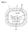
- the first shake preventing portions RC3 preferably are circumferentially arranged at substantially even intervals, and/or preferably have substantially triangular or pointed or converging cross sections projecting substantially in radially outward directions (see FIGS. 3 and 5 ).
- One or more, preferably a plurality of second shake preventing portions 52a are formed at or near the rear end of the inner circumferential surface of the covering portion 52 of the female housing 5. Similar to the first shake preventing portions RC3, the second shake preventing portions 52a preferably are circumferentially arranged at substantially even intervals and/or have substantially triangular or pointed or converging cross sections projecting substantially in radially inward directions.
- the terminal holding portion 51 having the holding cap RC mounted thereon is at least partly inserted into the receptacle 21 and, simultaneously, the covering portion 52 is at least partly fitted on or to the receptacle 21.
- the male terminals 3 of the male connector 1 are at least partly inserted into the holding cap RC through the connection holes RC2 to be mated with the female terminals 6 for electrical connection.
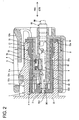
- the lock portion 21 a of the male housing 2 is engaged with the lock hole 53a to lock both housings 2, 5 into each other (see FIG. 2 ) after resiliently deforming the lock piece 53 of the female housing 5 outward (upward).
- the terminal holding portion 51 is engaged with the receptacle 21 preferably substantially up to the rear side thereof, and the one or more projections 71 of the mounted waterproof seal 7 are pressed against the inner circumferential surface of the receptacle 21 to prevent the entrance of water or other fluids into the terminal holding portion 51 from the outside.
- the leading end of the receptacle 21 presses the flexible flange portion 72 of the waterproof seal 7 preferably substantially backward to be resiliently engaged therewith, thereby reducing the shaking between the male and female housings 2, 5 in the connecting directions CD preferably in addition to displaying a water-entrance preventing function of the waterproof seal 7 (see FIGS. 2 and 4 ).
- the holding cap RC and the covering portion 52 of the female connector 4 are at least partly fitted into and onto the receptacle 21 of the male connector 1, whereby the first shake preventing portions RC3 come to be located between the holding cap RC and the inner circumferential surface of the receptacle 21 at the back side of the receptacle 21 (see FIGS. 2 , 3 and 5 ) and the second shake preventing portions 52a come to be located between the covering portion 52 and the outer circumferential surface of the receptacle 21 at the opening side of the receptacle 21 (see FIG. 2 ).
- the outer diameter of the holding cap RC including the first shake preventing portions RC3 preferably is slightly larger than the inner diameter of the back side of the receptacle 21 as shown in FIGS. 3 and 5 , the holding cap RC is at least partly inserted into the receptacle 21 while being slightly squeezed. As a result, the receptacle 21 becomes suitably strained. This enables the shaking between the holding cap RC and the receptacle 21 to be perfectly eliminated. Further, since the inner diameter of the covering portion 52 including the second shake preventing portions 52a preferably is smaller than the outer diameter of the receptacle 21 as shown in FIG.
- the receptacle 21 is slightly squeezed by the covering portion 52 similar to the aforementioned holding cap RC when the covering portion 52 is at least partly fitted on or to the receptacle 21.
- the covering portion 52 becomes suitably strained. This enables the shaking between the covering portion 52 and the receptacle 21 to be perfectly eliminated.
- the receptacle 21, the holding cap RC and the covering portion 52 are engaged with suitable tightening margins, whereby rigidity can be increased at engaged positions. Even if a load is exerted to the connectors 1, 4 connected with each other, they are not resiliently deformed. Alternatively, the shaking of both sides may be eliminated by engaging the receptacle 21, the holding cap RC and the covering portion 52 to have the tips of the first shake preventing portions RC3 and the second shake preventing portions 52a pressed by the receptacle 21 to be squeezed.
- first shake preventing portions RC3 and/or the second shake preventing portions 52a preferably are substantially circumferentially arranged at even intervals on the holding cap RC and/or the covering portion 52, a connection load is not increased too much at the time of engaging the holding cap RC and/or the covering portion 52 with the receptacle 21 and, therefore, no problems arises even if the tightening margin is provided between the holding cap RC or the covering portion 52 and the receptacle 21.
- the first shake preventing portions RC3 are substantially in contact with the receptacle 21 at or near the back side of the receptacle 21 and/or the second shake preventing portions 52a are in contact therewith at or near the opening side of the receptacle 21 when the male and female connectors 1, 4 are engaged, thereby eliminating the shaking in radial directions between the male and female housings 2, 5.
- the leading end of the receptacle 21 preferably is resiliently engaged with the waterproof seal 7 to reduce the shaking substantially in the connecting directions CD. This enables the shaking between the male and female connectors 1, 4 to be reduced preferably substantially in three dimensional directions.
- first shake preventing portions RC3 and the second shake preventing portions 52a preferably are parts of the holding cap RC and the female housing 5 both having rigidity, they are not deformed even if an excessive load acts substantially in a radial direction between both housings 2, 5, wherefore the connected connectors 1, 4 do not shake.
- parts to be engaged with the receptacle 21 are the holding cap RC at least partly insertable into the receptacle 21 and the covering portion 52 at least partly fittable on or to the outer circumferential surface of the receptacle 21.
- the first shake preventing portions RC3 preferably come to be located between the holding cap RC and the inner circumferential surface of the receptacle 21 and/or the second shake preventing portions 52a preferably come to be located between the covering portion 52 and the outer circumferential surface of the receptacle 21.
- a degree of freedom in designing parts where the first and second shake preventing portions RC3, 52a are formed is increased, wherefore it is possible to provide them in the housing 5 or the like while avoiding interference with the waterproof seal 7 and the like.
- a holding cap RC is to be mounted on or near or at a terminal holding portion 51 of a female housing 5 preferably substantially from front, and a tubular covering portion 52 is so at least partly formed radially outward of the terminal holding portion 51 as to at least partly surround the holding cap RC.
- One or more, preferably a plurality of first shake preventing portions RC3 project substantially radially outward from the outer circumferential surface of or near the front end of the holding cap RC.
- one or more, preferably a plurality of second shake preventing portions 52a project substantially radially inward at or near the rear end of the inner circumferential surface of the covering portion 52.
- first and second shake preventing portions RC3, 52a both come to be held substantially in contact with a receptacle 21 of a male housing 2, thereby being able to reduce the shaking between both housings 2, 5 substantially in radial directions.
Landscapes
- Connector Housings Or Holding Contact Members (AREA)
- Details Of Connecting Devices For Male And Female Coupling (AREA)
Claims (10)
- Connecteur (1) comprenant :un boîtier (2) formé avec un réceptacle (21) ayant un côté avant ouvert, et au moins une borne (3) montée dans le boîtier (2) de manière à être au moins en partie entourée par le réceptacle (21), dans lequel le boîtier (2) est connectable avec un boîtier complémentaire (5) d'un connecteur complémentaire (4) ayant une partie d'accouplement (51 ; 52 ; RC) formée dans le boîtier complémentaire (5) de manière à recevoir au moins en partie une borne (6) à l'intérieur, la partie d'accouplement (51 ; 52 ; RC) du boîtier complémentaire (5) pouvant être au moins en partie ajustée dans le réceptacle (21) du boîtier (2) pour connecter les deux bornes (3, 6) l'une à l'autre par accouplement du connecteur (1) avec le connecteur complémentaire (4),caractérisé en ce que le connecteur comprend en outre une ou plusieurs premières et deuxièmes parties anti-secousse (RC3, 52a) qui font radialement saillie dans le réceptacle (21), les premières parties anti-secousse (RC3) doivent être maintenues sensiblement en contact avec le boîtier complémentaire (5) à l'endroit ou près du côté arrière du réceptacle (21) et les deuxièmes parties anti-secousse (52a) doivent être maintenues sensiblement en contact avec le boîtier complémentaire (5) à l'endroit ou près du côté d'ouverture du réceptacle (21), afin de réduire les secousses entre le boîtier (2) et le boîtier complémentaire (5) dans des directions radiales lorsqu'on accouple le connecteur (1) avec le connecteur complémentaire (4).
- Connecteur complémentaire (4) comprenant :un boîtier complémentaire (5) ayant une partie d'accouplement (51 ; 52 ; RC) formée dans le boîtier complémentaire (5) pour recevoir au moins en partie une borne (6) à l'intérieur, dans lequel la partie d'accouplement (51 ; 52 ; RC) du boîtier complémentaire (5) peut au moins en partie s'ajuster dans un boîtier (2) d'un connecteur (1) qui comporte un réceptacle (21) ayant un côté avant ouvert, et au moins une borne (3) montée dans le boîtier (2) de manière à être au moins en partie entourée par le réceptacle (21), afin de connecter les deux bornes (3, 6) l'une à l'autre par accouplement du connecteur complémentaire (4) avec le connecteur (1),caractérisé en ce qu'une ou plusieurs premières et deuxièmes parties anti-secousse (RC3, 52a) font saillie radialement à partir de la partie d'accouplement (51 ; 52 ; RC), les premières parties anti-secousse (RC3) doivent être maintenues sensiblement en contact avec le boîtier (2) à l'endroit ou près du côté arrière du réceptacle (21) et les deuxièmes parties anti-secousse (52a) doivent être maintenues sensiblement en contact avec le boîtier (2) à l'endroit ou près du côté d'ouverture du réceptacle (21), afin de réduire les secousses entre le boîtier complémentaire (5) et le boîtier (2) dans des directions radiales, lorsqu'on accouple le connecteur complémentaire (4) avec le connecteur (1).
- Connecteur (1 ; 4) selon la revendication 1 ou 2, dans lequel l'extrémité de tête du réceptacle (21) peut être élastiquement accouplée avec le connecteur complémentaire (4), afin de réduire les secousses entre le boîtier (2) et le boîtier complémentaire (5) sensiblement dans les directions d'accouplement (CD) des deux boîtiers (2, 5).
- Connecteur (1 ; 4) selon une ou plusieurs des revendications précédentes, dans lequel la partie d'accouplement (51 ; 52 ; RC) comprend une partie de maintien de borne (51) au moins en partie insérable dans le réceptacle (21) et/ou une partie de couverture (52) ajustable sur la partie circonférentielle extérieure du réceptacle (21).
- Connecteur (1 ; 4) selon la revendication 4, dans lequel les premières parties anti-secousse (RC3) ou les deuxièmes parties anti-secousse (52a) sont situées entre la surface circonférentielle intérieure du réceptacle (21) et la partie de maintien de borne (51), et les autres sont situées entre la surface circonférentielle extérieure du réceptacle (21) et la partie de couverture (52).
- Connecteur (1 ; 4) selon une ou plusieurs des revendications précédentes, dans lequel un joint d'étanchéité à l'eau (7) doit être monté sur ou dans le boîtier complémentaire (5) et une extrémité de tête du réceptacle (21) presse une collerette flexible (72) du joint d'étanchéité (7) de préférence sensiblement vers l'arrière de manière à être élastiquement en contact avec elle, ce qui réduit les secousses entre le boîtier (2) et le boîtier complémentaire (5) sensiblement dans les directions d'accouplement (CD) de préférence, en plus de présenter une fonction d'empêchement d'entrée d'eau du joint étanche (7).
- Connecteur (1 ; 7) selon une ou plusieurs des revendications précédentes, dans lequel un diamètre extérieur de la partie d'accouplement (51 ; 52 ; RC) incluant les premières parties anti-secousse (RC3) est légèrement plus grand que le diamètre intérieur du côté arrière du réceptacle (21), de sorte que la partie d'accouplement (51 ; 52 ; RC) est de préférence au moins en partie insérable dans le réceptacle (21) tout en étant légèrement comprimée.
- Connecteur (1 ; 4) selon une ou plusieurs des revendications précédentes, dans lequel un diamètre intérieur de la partie d'accouplement (51 ; 52 ; RC) incluant les deuxièmes parties anti-secousse (52a) est plus petit que le diamètre extérieur du réceptacle (21), de sorte que le réceptacle (21) est de préférence légèrement comprimé par la partie d'accouplement (51 ; 52 ; RC) lorsque la partie d'accouplement (51 ; 52 ; RC) est au moins en partie ajustée sur ou dans le réceptacle (21).
- Connecteur (1 ; 4) selon une ou plusieurs des revendications précédentes, dans lequel les premières parties anti-secousse (RC3) et/ou les deuxièmes parties anti-secousse (52a) sont agencées circonférentiellement à des intervalles sensiblement égaux.
- Dispositif de connexion comprenant un connecteur (1) selon une ou plusieurs des revendications précédente en combinaison avec la revendication 1 et un connecteur complémentaire (4) selon une ou plusieurs des revendications précédentes en combinaison avec la revendication 2.
Applications Claiming Priority (1)
| Application Number | Priority Date | Filing Date | Title |
|---|---|---|---|
| JP2005268945A JP2007080737A (ja) | 2005-09-15 | 2005-09-15 | コネクタ装置 |
Publications (2)
| Publication Number | Publication Date |
|---|---|
| EP1764877A1 EP1764877A1 (fr) | 2007-03-21 |
| EP1764877B1 true EP1764877B1 (fr) | 2008-05-07 |
Family
ID=37052538
Family Applications (1)
| Application Number | Title | Priority Date | Filing Date |
|---|---|---|---|
| EP06019104A Expired - Fee Related EP1764877B1 (fr) | 2005-09-15 | 2006-09-12 | Connecteur , pièce complémentaire et dispositif de connexion |
Country Status (4)
| Country | Link |
|---|---|
| US (1) | US7311546B2 (fr) |
| EP (1) | EP1764877B1 (fr) |
| JP (1) | JP2007080737A (fr) |
| DE (1) | DE602006001089D1 (fr) |
Cited By (1)
| Publication number | Priority date | Publication date | Assignee | Title |
|---|---|---|---|---|
| CN109478741A (zh) * | 2016-07-14 | 2019-03-15 | 泰连德国有限公司 | 带有振动吸收器的减振连接器 |
Families Citing this family (22)
| Publication number | Priority date | Publication date | Assignee | Title |
|---|---|---|---|---|
| JP2007080737A (ja) * | 2005-09-15 | 2007-03-29 | Sumitomo Wiring Syst Ltd | コネクタ装置 |
| JP4702205B2 (ja) * | 2006-07-04 | 2011-06-15 | 住友電装株式会社 | コネクタ |
| JP2008108487A (ja) * | 2006-10-24 | 2008-05-08 | Sumitomo Wiring Syst Ltd | コネクタ |
| JP5034685B2 (ja) * | 2007-05-31 | 2012-09-26 | 住友電装株式会社 | コネクタ |
| DE102008028325B4 (de) | 2007-06-19 | 2011-02-03 | Sumitomo Wiring Systems, Ltd., Yokkaichi-shi | Fluiddichter Verbinder und Verbinderanordnung |
| JP2009110896A (ja) * | 2007-11-01 | 2009-05-21 | Yazaki Corp | コネクタ |
| KR101020542B1 (ko) * | 2007-12-12 | 2011-03-09 | 현대자동차주식회사 | 에이비에스용 커넥터의 전원 터미널 구조 |
| DE102009003016B4 (de) * | 2009-05-11 | 2019-11-21 | Ifm Electronic Gmbh | Rundsteckverbinder für Industrieanwendungen |
| DE102009048481B4 (de) * | 2009-10-07 | 2020-02-20 | Kostal Kontakt Systeme Gmbh | Elektrischer Steckverbinder |
| JP2013516032A (ja) * | 2009-12-24 | 2013-05-09 | エフシーアイ・オートモティヴ・ホールディング | 電気コネクタ組立体 |
| JP5721332B2 (ja) | 2010-03-05 | 2015-05-20 | 矢崎総業株式会社 | モータケースに設置されたインバータ端子台 |
| DE102013209367A1 (de) | 2013-05-21 | 2014-11-27 | Continental Automotive Gmbh | Kontaktvorrichtung zum Herstellen eines elektrischen Kontaktes zwischen einer Leiterplatinen und einem Elektromotor |
| JP6215068B2 (ja) * | 2014-01-28 | 2017-10-18 | 日本航空電子工業株式会社 | コネクタ |
| JP2015162278A (ja) * | 2014-02-26 | 2015-09-07 | 住友電装株式会社 | サービスカバー |
| JP6150174B2 (ja) * | 2014-05-16 | 2017-06-21 | 住友電装株式会社 | コネクタ |
| JP6404277B2 (ja) | 2016-07-12 | 2018-10-10 | 矢崎総業株式会社 | コネクタ |
| JP6511027B2 (ja) | 2016-09-27 | 2019-05-08 | 矢崎総業株式会社 | レバー式コネクタ |
| JP2018067466A (ja) | 2016-10-20 | 2018-04-26 | 住友電装株式会社 | 防水コネクタ |
| JP6660409B2 (ja) | 2018-02-13 | 2020-03-11 | 矢崎総業株式会社 | コネクタ |
| JP6997951B2 (ja) * | 2018-03-26 | 2022-01-18 | 住友電装株式会社 | 基板用コネクタ |
| JP2019175628A (ja) * | 2018-03-28 | 2019-10-10 | 住友電装株式会社 | コネクタ及び防水コネクタ |
| JP7109872B2 (ja) * | 2020-09-09 | 2022-08-01 | 矢崎総業株式会社 | コネクタハウジング及びワイヤハーネス |
Family Cites Families (13)
| Publication number | Priority date | Publication date | Assignee | Title |
|---|---|---|---|---|
| NL274408A (fr) * | 1961-02-21 | |||
| US3846736A (en) * | 1972-08-02 | 1974-11-05 | Nicolay Gmbh | Insulated electrical conductor for panel mounting |
| US4333699A (en) * | 1978-01-18 | 1982-06-08 | Gk Technologies, Incorporated | Flat telephone cord plug improvements |
| US4449776A (en) * | 1982-09-13 | 1984-05-22 | Pacific Electricord Company | Electrical connector having opposed locking ramp members |
| DE8508972U1 (de) * | 1985-03-26 | 1986-03-27 | Schulte-Elektrotechnik GmbH & Co KG, 5880 Lüdenscheid | Steckerkupplung |
| JPH0550113A (ja) | 1991-08-23 | 1993-03-02 | Toshiba Corp | クロツプ長切断位置検出装置 |
| JP3478385B2 (ja) * | 2000-05-11 | 2003-12-15 | 住友電装株式会社 | 防水コネクタ |
| JP2003133002A (ja) * | 2001-08-17 | 2003-05-09 | Yazaki Corp | コネクタとコネクタハウジング |
| JP2005174813A (ja) * | 2003-12-12 | 2005-06-30 | Yazaki Corp | コネクタ |
| JP4332154B2 (ja) | 2003-12-26 | 2009-09-16 | 矢崎総業株式会社 | コネクタ |
| DE102005008585B4 (de) * | 2004-02-25 | 2013-05-16 | Sumitomo Wiring Systems, Ltd. | Verbinderanordnung |
| JP4345594B2 (ja) * | 2004-07-02 | 2009-10-14 | 住友電装株式会社 | コネクタ |
| JP2007080737A (ja) * | 2005-09-15 | 2007-03-29 | Sumitomo Wiring Syst Ltd | コネクタ装置 |
-
2005
- 2005-09-15 JP JP2005268945A patent/JP2007080737A/ja not_active Abandoned
-
2006
- 2006-09-12 EP EP06019104A patent/EP1764877B1/fr not_active Expired - Fee Related
- 2006-09-12 DE DE602006001089T patent/DE602006001089D1/de active Active
- 2006-09-13 US US11/520,122 patent/US7311546B2/en not_active Expired - Fee Related
Cited By (3)
| Publication number | Priority date | Publication date | Assignee | Title |
|---|---|---|---|---|
| CN109478741A (zh) * | 2016-07-14 | 2019-03-15 | 泰连德国有限公司 | 带有振动吸收器的减振连接器 |
| US10847928B2 (en) | 2016-07-14 | 2020-11-24 | Te Connectivity Germany Gmbh | Vibration-attentuating connector with an oscillation absorber |
| CN109478741B (zh) * | 2016-07-14 | 2022-02-25 | 泰连德国有限公司 | 带有振动吸收器的减振连接器 |
Also Published As
| Publication number | Publication date |
|---|---|
| DE602006001089D1 (de) | 2008-06-19 |
| EP1764877A1 (fr) | 2007-03-21 |
| US7311546B2 (en) | 2007-12-25 |
| JP2007080737A (ja) | 2007-03-29 |
| US20070059967A1 (en) | 2007-03-15 |
Similar Documents
| Publication | Publication Date | Title |
|---|---|---|
| EP1764877B1 (fr) | Connecteur , pièce complémentaire et dispositif de connexion | |
| CN108352649B (zh) | 连接器 | |
| EP0932918B1 (fr) | Connecteur electrique etanche | |
| US6494731B1 (en) | Waterproof connector | |
| JP5949628B2 (ja) | コネクタ | |
| US7458838B2 (en) | Fluidtight connector | |
| US7448894B2 (en) | Waterproof connector | |
| US5836788A (en) | Waterproof press-connecting connector | |
| CN110226266A (zh) | 屏蔽连接器及阳侧屏蔽端子 | |
| US7419395B2 (en) | Small double-locking waterproof connector | |
| CN101390260A (zh) | 连接器壳体的防水结构 | |
| EP3751675A1 (fr) | Boîtier comprenant une pièce d'engagement insérée dans une partie de montage de joint et butant contre cette partie de montage de joint | |
| EP1821372B1 (fr) | Connecteur et méthode de montage | |
| US6024606A (en) | Connector plug | |
| US20030032321A1 (en) | Sealed connector | |
| EP1548894B1 (fr) | Connecteur | |
| US6783396B1 (en) | Airtight plug connector and terminal insert | |
| CN103765693B (zh) | 连接器及其覆盖部件 | |
| JP5258802B2 (ja) | プラグ電気コネクタ及びこれとレセプタクル電気コネクタとを有する電気コネクタ組立体 | |
| JP2004171831A (ja) | シールドコネクタ | |
| JP2005285333A (ja) | 単体防水クリンプコネクタ及びその組立方法 | |
| JP2005158396A (ja) | コネクタ | |
| JP5692600B2 (ja) | ジョイントコネクタ | |
| JP3415055B2 (ja) | 嵌合検知コネクタ | |
| EP3020096B1 (fr) | Ensemble de connecteur amélioré avec joint d'étanchéité |
Legal Events
| Date | Code | Title | Description |
|---|---|---|---|
| PUAI | Public reference made under article 153(3) epc to a published international application that has entered the european phase |
Free format text: ORIGINAL CODE: 0009012 |
|
| 17P | Request for examination filed |
Effective date: 20060921 |
|
| AK | Designated contracting states |
Kind code of ref document: A1 Designated state(s): AT BE BG CH CY CZ DE DK EE ES FI FR GB GR HU IE IS IT LI LT LU LV MC NL PL PT RO SE SI SK TR |
|
| AX | Request for extension of the european patent |
Extension state: AL BA HR MK YU |
|
| GRAP | Despatch of communication of intention to grant a patent |
Free format text: ORIGINAL CODE: EPIDOSNIGR1 |
|
| AKX | Designation fees paid |
Designated state(s): DE FR |
|
| GRAS | Grant fee paid |
Free format text: ORIGINAL CODE: EPIDOSNIGR3 |
|
| GRAA | (expected) grant |
Free format text: ORIGINAL CODE: 0009210 |
|
| AK | Designated contracting states |
Kind code of ref document: B1 Designated state(s): DE FR |
|
| REF | Corresponds to: |
Ref document number: 602006001089 Country of ref document: DE Date of ref document: 20080619 Kind code of ref document: P |
|
| PLBE | No opposition filed within time limit |
Free format text: ORIGINAL CODE: 0009261 |
|
| STAA | Information on the status of an ep patent application or granted ep patent |
Free format text: STATUS: NO OPPOSITION FILED WITHIN TIME LIMIT |
|
| 26N | No opposition filed |
Effective date: 20090210 |
|
| PGFP | Annual fee paid to national office [announced via postgrant information from national office to epo] |
Ref country code: DE Payment date: 20130904 Year of fee payment: 8 |
|
| PGFP | Annual fee paid to national office [announced via postgrant information from national office to epo] |
Ref country code: FR Payment date: 20130910 Year of fee payment: 8 |
|
| REG | Reference to a national code |
Ref country code: DE Ref legal event code: R119 Ref document number: 602006001089 Country of ref document: DE |
|
| REG | Reference to a national code |
Ref country code: DE Ref legal event code: R119 Ref document number: 602006001089 Country of ref document: DE Effective date: 20150401 |
|
| REG | Reference to a national code |
Ref country code: FR Ref legal event code: ST Effective date: 20150529 |
|
| PG25 | Lapsed in a contracting state [announced via postgrant information from national office to epo] |
Ref country code: DE Free format text: LAPSE BECAUSE OF NON-PAYMENT OF DUE FEES Effective date: 20150401 |
|
| PG25 | Lapsed in a contracting state [announced via postgrant information from national office to epo] |
Ref country code: FR Free format text: LAPSE BECAUSE OF NON-PAYMENT OF DUE FEES Effective date: 20140930 |