EP1764892A1 - Vorrichtung zur Überwachung eines Fehlerstromes am Ausgang einer Energiequelle eines Kraftfahrzeuges - Google Patents
Vorrichtung zur Überwachung eines Fehlerstromes am Ausgang einer Energiequelle eines Kraftfahrzeuges Download PDFInfo
- Publication number
- EP1764892A1 EP1764892A1 EP06120643A EP06120643A EP1764892A1 EP 1764892 A1 EP1764892 A1 EP 1764892A1 EP 06120643 A EP06120643 A EP 06120643A EP 06120643 A EP06120643 A EP 06120643A EP 1764892 A1 EP1764892 A1 EP 1764892A1
- Authority
- EP
- European Patent Office
- Prior art keywords
- branch
- current
- measuring
- switch
- analysis
- Prior art date
- Legal status (The legal status is an assumption and is not a legal conclusion. Google has not performed a legal analysis and makes no representation as to the accuracy of the status listed.)
- Withdrawn
Links
- 238000012544 monitoring process Methods 0.000 title claims abstract description 9
- 238000004458 analytical method Methods 0.000 claims abstract description 34
- 238000005259 measurement Methods 0.000 claims abstract description 29
- 238000012806 monitoring device Methods 0.000 description 13
- 238000001514 detection method Methods 0.000 description 3
- 238000010586 diagram Methods 0.000 description 2
- 230000007423 decrease Effects 0.000 description 1
- 230000007547 defect Effects 0.000 description 1
- 238000012986 modification Methods 0.000 description 1
- 230000004048 modification Effects 0.000 description 1
- 230000002035 prolonged effect Effects 0.000 description 1
Images


Classifications
-
- H—ELECTRICITY
- H02—GENERATION; CONVERSION OR DISTRIBUTION OF ELECTRIC POWER
- H02H—EMERGENCY PROTECTIVE CIRCUIT ARRANGEMENTS
- H02H3/00—Emergency protective circuit arrangements for automatic disconnection directly responsive to an undesired change from normal electric working condition with or without subsequent reconnection ; integrated protection
- H02H3/08—Emergency protective circuit arrangements for automatic disconnection directly responsive to an undesired change from normal electric working condition with or without subsequent reconnection ; integrated protection responsive to excess current
- H02H3/087—Emergency protective circuit arrangements for automatic disconnection directly responsive to an undesired change from normal electric working condition with or without subsequent reconnection ; integrated protection responsive to excess current for DC applications
-
- H—ELECTRICITY
- H02—GENERATION; CONVERSION OR DISTRIBUTION OF ELECTRIC POWER
- H02H—EMERGENCY PROTECTIVE CIRCUIT ARRANGEMENTS
- H02H7/00—Emergency protective circuit arrangements specially adapted for specific types of electric machines or apparatus or for sectionalised protection of cable or line systems, and effecting automatic switching in the event of an undesired change from normal working conditions
- H02H7/18—Emergency protective circuit arrangements specially adapted for specific types of electric machines or apparatus or for sectionalised protection of cable or line systems, and effecting automatic switching in the event of an undesired change from normal working conditions for batteries; for accumulators
Definitions
- the object of the invention relates to a device for detecting the appearance of a fault current at the output of an energy source of a motor vehicle.
- the object of the invention finds a particularly advantageous application in the field of monitoring a battery of a motor vehicle to prevent its discharge.
- a motor vehicle In general, a motor vehicle is equipped with at least one battery which, even when the vehicle is stationary, supplies certain electrical and / or electronic equipment for a fixed period of time. This is the case of anti-theft devices, door locking systems, security lights, etc. In the same direction, certain equipment such as computers, electronic circuits or actuators regularly request the supply of an electrical energy to ensure different associated functions.
- a monitoring device comprises a current measuring circuit with a resistance interposed between the output of the battery and the charges supplied by the battery.
- Such a device also comprises a management unit which, depending on the measurement of the current, controls the opening of a switch mounted at the output of the battery to disconnect loads in the event of the appearance of a fault current.
- the measurement resistance traversed by the current generates a voltage drop, which decreases the voltage applied to the energized loads.
- the current passing through this resistance during the vehicle running phases is important (a few hundred amperes) as well as during current requests by the computers or actuators during the stopping phases of the vehicle (a few tens of amps). ).
- the object of the invention is therefore to provide a device for accurately measuring, via ohmic resistance, a fault current such as a short-circuit or a leakage current, without causing a voltage drop. high compared to the charges powered by the battery.
- the device for monitoring the appearance of a fault current at the output of at least one energy source of a vehicle, supplying a series of electric charges is intended to be mounted to the output of the energy source which has, on the one hand, a highly current operating mode corresponding to a current supply of the electrical charges and, on the other hand, a mode of operation out of high current.
- the analysis and control means control the opening of cut-off means during the detection of the appearance of a fault current.
- the breaking means consist of at least one switch connected in series in the measuring branch.
- the breaking means consist of a switch placed at the output of the energy source or in series with at least one electric charge.
- the analysis and control means control the opening of the switch connected in series in the measuring branch when the power source is in a high current mode.
- the current measuring means comprises a resistor and a circuit for measuring the current flowing through the resistor.
- the current means provide a measurement of the current flowing in the measuring branch when the switch is closed.
- the analysis and control means ensure the opening of the breaking means and the switch placed in the branch branch according to the stopping state of the vehicle .
- the analysis and control means control the closing of the breaking means to allow a measurement of current in the measurement branch.
- the analysis and control means are an integral part of the device or are wholly or partly deported in a computer.
- Another object of the invention is to propose a system for monitoring the electrical state of a vehicle comprising a device according to the invention.
- the object of the invention relates to a device 1 adapted to monitor the appearance of a fault current at the output of at least one energy source 2 of a motor vehicle.
- the energy source 2 supplies a series of electric charges 3 and is composed of a battery connected in parallel with an alternator.
- the monitoring device 1 is intended to be mounted at the output of the energy source 2.
- the device 1 is in the form of a housing interposed between the energy source 2 and the electric charges 3.
- the monitoring device 1 comprises a branch 5 of current measurement connected in parallel with a branch branch 7 which has an electrical resistance lower than the electrical resistance of the measuring branch 5.
- the measuring branch 5 is equipped with a resistor 8 called shunt forming part of measuring means current 9.
- Branch branch 7 comprises at least one controlled switch 11 for opening or closing branch branch 7. It must be considered that branch branch 7 is weakly resistive so that the resistance is for example less than 10 m ⁇ and preferably between 1 and 10 m ⁇ .
- the measuring branch 5 is highly resistive so that the resistance is for example greater than 100 m ⁇ and typically of the order of a few hundred m ⁇ , and preferably between 100 m ⁇ and 10 ⁇ .
- the resistance of the branch branch 7 and the resistance of the measuring branch 5 are known and determined at values indicated above.
- the measuring means 9 also comprises a measuring circuit 12 for the current flowing through the measuring branch 5 and more precisely the resistor 8.
- This measuring circuit 12 can be produced in any appropriate manner, for example by implementing an amplifier placed at the terminals resistance 8.
- the monitoring device 1 also comprises analysis and control means 13 connected to the controlled switch 11 and to the measuring circuit 12. These analysis and control means 13 are also connected to information means 15 giving information on the state of the energy supplied by the energy source 2.
- the energy source 2 has a high current mode of operation and a mode of operation out of strong current.
- the high-current operating mode appears when the vehicle is running (a few hundred amperes) or when the vehicle is stationary but certain loads such as actuators or computers require a current for a specified period of time (a few tens of amps).
- the energy source 2 also has a mode of operation out of high current that can be described as operating mode at low current.
- the information means 15 provide the analysis and control means 13 with information on the operating state of the energy source (high current mode or off-current mode) which depends on the energy demands of the various loads 3.
- the analysis and control means 13 thus make it possible, on the one hand, to close the switch 11 when the battery is operating in a high current mode and, on the other hand, when the battery is in a high current mode, to open the switch. 11 and measure the current flowing in the measuring branch 5 to detect the occurrence of a fault current.
- branch branch 7 is closed so that it appears a very low resistance and therefore a very small drop in voltage even though the circulating current can be of significant value.
- a resistance of a few m ⁇ may be provided for branch branch 7 so that there is a slight voltage drop below Volt.
- the shunt is all the better that the resistance of the shunt branch 7 is much smaller than the resistance of the measurement branch 5.
- the measuring means 9 can provide a measurement of the current flowing in the measuring branch 5. This measurement of the current flowing in the measuring branch 5 makes it possible to know the total current supplied by the battery in so far as is known the ratio of the resistances between the branch branch 7 and the measuring branch 5.
- the bypass branch 7 is opened by the opening of the switch 11, so that the current passes only in the measurement branch 5.
- the analysis and control means 13 thus make it possible to detect the appearance of a fault current at the terminals of the energy source 2.
- the monitoring device 1 thus makes it possible to accurately measure the current while not causing a voltage drop of the energy source. It should be noted that this current measurement is effective mainly when discharged as a source of energy 2, the battery.
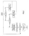
- Fig. 2 makes it possible to explain the operation of the monitoring device according to the invention.
- the monitoring device 1 takes into account as information the running of the vehicle. If the vehicle is running, the analysis and control means 13 control the closing of the controlled switch 11 so that the power source can be discharged into the loads 3 via the branch branch 7. If the vehicle is at stopping, the monitoring device 1 takes into account whether or not there appears to be a high current requirement with at least one load. If the need for a high current appears, the analysis and control means 13 control the closing of the controlled switch 11 in order to supply the loads 3, via the branch branch 7.
- the analysis and control means 13 control the opening of the switch 11 of the branch branch 7 and the closing of the switch 16 of the measurement branch 5.
- the means 12 measure the current flowing in the measuring branch 5 in order to assess whether the current flowing or not corresponds to a fault current.
- Fig. 3 illustrates a preferred embodiment in which the analysis and control means 13 control the opening of cut-off means 16 during the detection of the appearance of a fault current.
- the switching means 16 are constituted by at least one switch connected in series in the measurement branch 5.
- the analysis and control means 13 When the analysis and control means 13 detect the appearance of a fault current, the analysis and control means 13 control the opening of the switch 16 in order to disconnect the charges 3 from the source of the fault. energy. When both switches 11 and 16 are in the open position, the energy source 2 is isolated and protected from inadvertent discharge.
- the analysis and control means 13 also take into account according to the embodiment variant illustrated in FIG. 3, a disconnect command if the value of the measured current exceeds a determined value or does not correspond to a particular demand of a load.
- the switch 16 is open.
- the analysis and control means 13 can control the opening of the switch 16 as a function of the stopping state of the vehicle.
- the switch 16 can be opened following a desire to disconnect the energy source for example before the marketing of the vehicle or following a prolonged stop of the vehicle for a predetermined period.
- the monitoring device In the case where the disconnection order is not given, the monitoring device remains in this state until a different information does not appear at the level of the running of the vehicle or a current requirement.
- the switch 16 is preferably placed in the measuring branch 5.
- the switch 16 can be placed directly at the output of the energy source or in series with one or more electric charges 3.
- the analysis and control means 13 can control the opening of the switch 16 placed in the measurement branch 5 when the power source is in a high current mode, that is, that is, when the switch 11 is closed.
- the switch 16 is closed by the analysis and control means 13 when a measurement of current is made, in off-current mode or in strong current mode.
- the analysis and control means 13 are considered to be an integral part of the device 1. Of course, it can be envisaged that these analysis and control means 13 are wholly or partly remote to the outside. of the device 1. Thus, part or all of the analysis and control means 13 can be deported in a computer associated with the vehicle.
- the monitoring device 1 can be part of a system for monitoring the electrical state of the vehicle.
- the device 1 can be integrated into a system for monitoring or protecting the battery against a discharge or to protect a vehicle against fire.
Landscapes
- Electric Propulsion And Braking For Vehicles (AREA)
- Secondary Cells (AREA)
- Charge And Discharge Circuits For Batteries Or The Like (AREA)
Applications Claiming Priority (1)
| Application Number | Priority Date | Filing Date | Title |
|---|---|---|---|
| FR0509374A FR2890797B1 (fr) | 2005-09-14 | 2005-09-14 | Dispositif pour surveiller l'apparition d'un courant de defaut a la sortie d'une source d'energie d'un vehicule |
Publications (1)
| Publication Number | Publication Date |
|---|---|
| EP1764892A1 true EP1764892A1 (de) | 2007-03-21 |
Family
ID=36579123
Family Applications (1)
| Application Number | Title | Priority Date | Filing Date |
|---|---|---|---|
| EP06120643A Withdrawn EP1764892A1 (de) | 2005-09-14 | 2006-09-14 | Vorrichtung zur Überwachung eines Fehlerstromes am Ausgang einer Energiequelle eines Kraftfahrzeuges |
Country Status (2)
| Country | Link |
|---|---|
| EP (1) | EP1764892A1 (de) |
| FR (1) | FR2890797B1 (de) |
Cited By (4)
| Publication number | Priority date | Publication date | Assignee | Title |
|---|---|---|---|---|
| FR2909813A1 (fr) * | 2006-12-08 | 2008-06-13 | Peugeot Citroen Automobiles Sa | Procede et dispositif de gestion de courants anormaux dans un reseau electrique de vehicule automobile |
| US8687334B2 (en) | 2010-03-17 | 2014-04-01 | Yazaki Corporation | Power feeding circuit |
| CN105871004A (zh) * | 2016-04-15 | 2016-08-17 | 智恒科技股份有限公司 | 功率型电池放电保护系统及其保护方法 |
| CN116097112A (zh) * | 2020-08-03 | 2023-05-09 | 伊莎贝尔努特·霍伊斯勒两合公司 | 用于车载电网的传感器 |
Citations (3)
| Publication number | Priority date | Publication date | Assignee | Title |
|---|---|---|---|---|
| US6710698B1 (en) * | 1999-09-02 | 2004-03-23 | Robert Bosch Gmbh | Semiconductor fuse for electrical consumers |
| EP1492210A1 (de) * | 2003-06-26 | 2004-12-29 | Peugeot Citroen Automobiles S.A. | Scutzsystem für zumindest eines Teils eines Kraftfahrzeugbordnetzes |
| FR2870996A1 (fr) * | 2004-05-28 | 2005-12-02 | Cartier Technologies Soc Par A | Protection de circuit electrique en mode veille pour vehicule |
-
2005
- 2005-09-14 FR FR0509374A patent/FR2890797B1/fr not_active Expired - Fee Related
-
2006
- 2006-09-14 EP EP06120643A patent/EP1764892A1/de not_active Withdrawn
Patent Citations (3)
| Publication number | Priority date | Publication date | Assignee | Title |
|---|---|---|---|---|
| US6710698B1 (en) * | 1999-09-02 | 2004-03-23 | Robert Bosch Gmbh | Semiconductor fuse for electrical consumers |
| EP1492210A1 (de) * | 2003-06-26 | 2004-12-29 | Peugeot Citroen Automobiles S.A. | Scutzsystem für zumindest eines Teils eines Kraftfahrzeugbordnetzes |
| FR2870996A1 (fr) * | 2004-05-28 | 2005-12-02 | Cartier Technologies Soc Par A | Protection de circuit electrique en mode veille pour vehicule |
Cited By (6)
| Publication number | Priority date | Publication date | Assignee | Title |
|---|---|---|---|---|
| FR2909813A1 (fr) * | 2006-12-08 | 2008-06-13 | Peugeot Citroen Automobiles Sa | Procede et dispositif de gestion de courants anormaux dans un reseau electrique de vehicule automobile |
| US8687334B2 (en) | 2010-03-17 | 2014-04-01 | Yazaki Corporation | Power feeding circuit |
| DE102011005716B4 (de) | 2010-03-17 | 2022-02-24 | Toyota Jidosha Kabushiki Kaisha | Stromversorgungs-Schaltkreis |
| CN105871004A (zh) * | 2016-04-15 | 2016-08-17 | 智恒科技股份有限公司 | 功率型电池放电保护系统及其保护方法 |
| CN105871004B (zh) * | 2016-04-15 | 2018-09-11 | 智恒科技股份有限公司 | 功率型电池放电保护系统及其保护方法 |
| CN116097112A (zh) * | 2020-08-03 | 2023-05-09 | 伊莎贝尔努特·霍伊斯勒两合公司 | 用于车载电网的传感器 |
Also Published As
| Publication number | Publication date |
|---|---|
| FR2890797A1 (fr) | 2007-03-16 |
| FR2890797B1 (fr) | 2007-12-14 |
Similar Documents
| Publication | Publication Date | Title |
|---|---|---|
| EP2457105B1 (de) | Diagnoseverfahren für den betrieb einer vorrichtung zum abtrennen und anschliessen einer battterie von einem bordstromnetz eines kraftfahrzeuges | |
| EP1764891B1 (de) | Elektronische Auslösevorrichtung mit Überwachungsmittel und entsprechendes Überwachungsverfahren | |
| WO2015022329A1 (fr) | Dispositif de commutation et protection a distance de systemes electriques | |
| EP0782265B1 (de) | Verfahren und Vorrichtung zum Schutz eines einstellbaren Impedanzelements zur Steuerung der Stromversorgung eines Elektromotors, insbesondere eines Kraftfahrzeugs | |
| FR3084468A1 (fr) | Procédé de diagnostic d’un moyen de commutation dans un véhicule automobile | |
| WO2015067730A2 (fr) | Commande sécurisée d'un réchauffeur électrique | |
| FR2825470A1 (fr) | Procede et dispositif pour detecter un defaut de court-circuit de charge et dispositif de direction a assistance electrique | |
| EP3614514B1 (de) | Elektrische oder elektronische vorrichtung mit zwei versorgungsspannungen | |
| EP1034592B1 (de) | Stromversorgungsnetz mit einer vorrichtung zum vorladen und einer kapazitiven last | |
| FR3006462A1 (fr) | Procede et dispositif de lecture de l'etat de variables de contact d'un vehicule automobile | |
| FR2890797A1 (fr) | Dispositif pour surveiller l'apparition d'un courant de defaut a la sortie d'une source d'energie d'un vehicule | |
| FR2978879A1 (fr) | Procede de diagnostic d'un court-circuit dans un ensemble electrique d'un vehicule automobile comprenant une composante capacitive et dispositif de diagnostic | |
| FR3050586A1 (fr) | Protection de l’alimentation electrique d’un vehicule | |
| FR3122362A1 (fr) | Ensemble et procédé de gestion d'un réseau électrique d'un véhicule automobile | |
| FR2870996A1 (fr) | Protection de circuit electrique en mode veille pour vehicule | |
| WO1999048183A1 (fr) | Bloc de moteur electrique, notamment pour vehicule automobile, integrant une electronique de commande | |
| WO2014013206A1 (fr) | Calculateur de regulation de moteur et procede de detection de pannes d'un tel calculateur | |
| EP1780552B1 (de) | Elektronische Einrichtung zur Erkennung der Anomalien elektrischer Kabelbäume eines Fahrzeuges | |
| FR3097057A1 (fr) | Procédé de diagnostic de connexion électrique défaillante dans un système électrique | |
| FR3080399A1 (fr) | Procede de commande d’une serrure electrique permettant de diagnostiquer une defaillance de la commande d’ouverture associee, commande d’ouverture et vehicule mettant en œuvre un tel procede | |
| WO2026027366A1 (fr) | Procédé de protection d'une branche de circuit électrique d'un véhicule automobile | |
| WO2025248190A1 (fr) | Dispositif et procédé de protection d'un équipement alimenté par un bus de haute tension continue | |
| FR3165325A1 (fr) | Procédé de contrôle de performance d’isolement électrique | |
| EP4496176A1 (de) | Vorrichtung zur regelung eines ladestroms für eine batterie und batterieverwaltungssystem mit einer solchen vorrichtung | |
| WO2025012455A1 (fr) | Dispositif de commande de verrouillage pour système de gestion des accumulateurs de batterie et système de gestion des accumulateurs de batterie équipé d'un tel dispositif |
Legal Events
| Date | Code | Title | Description |
|---|---|---|---|
| PUAI | Public reference made under article 153(3) epc to a published international application that has entered the european phase |
Free format text: ORIGINAL CODE: 0009012 |
|
| AK | Designated contracting states |
Kind code of ref document: A1 Designated state(s): AT BE BG CH CY CZ DE DK EE ES FI FR GB GR HU IE IS IT LI LT LU LV MC NL PL PT RO SE SI SK TR |
|
| AX | Request for extension of the european patent |
Extension state: AL BA HR MK YU |
|
| 17P | Request for examination filed |
Effective date: 20070913 |
|
| AKX | Designation fees paid |
Designated state(s): FR |
|
| 17Q | First examination report despatched |
Effective date: 20071119 |
|
| REG | Reference to a national code |
Ref country code: DE Ref legal event code: 8566 |
|
| STAA | Information on the status of an ep patent application or granted ep patent |
Free format text: STATUS: THE APPLICATION IS DEEMED TO BE WITHDRAWN |
|
| 18D | Application deemed to be withdrawn |
Effective date: 20140401 |