EP1764904A2 - Antriebsvorrichtung für einen Motor - Google Patents
Antriebsvorrichtung für einen Motor Download PDFInfo
- Publication number
- EP1764904A2 EP1764904A2 EP06019484A EP06019484A EP1764904A2 EP 1764904 A2 EP1764904 A2 EP 1764904A2 EP 06019484 A EP06019484 A EP 06019484A EP 06019484 A EP06019484 A EP 06019484A EP 1764904 A2 EP1764904 A2 EP 1764904A2
- Authority
- EP
- European Patent Office
- Prior art keywords
- motor
- control
- magnetic pole
- sensor
- pole position
- Prior art date
- Legal status (The legal status is an assumption and is not a legal conclusion. Google has not performed a legal analysis and makes no representation as to the accuracy of the status listed.)
- Withdrawn
Links
- 238000000034 method Methods 0.000 description 9
- 238000010586 diagram Methods 0.000 description 6
- 230000001360 synchronised effect Effects 0.000 description 4
- 230000004907 flux Effects 0.000 description 3
- CURLTUGMZLYLDI-UHFFFAOYSA-N Carbon dioxide Chemical compound O=C=O CURLTUGMZLYLDI-UHFFFAOYSA-N 0.000 description 2
- 230000008901 benefit Effects 0.000 description 2
- 230000006835 compression Effects 0.000 description 2
- 238000007906 compression Methods 0.000 description 2
- 239000003507 refrigerant Substances 0.000 description 2
- 230000004044 response Effects 0.000 description 2
- 238000012935 Averaging Methods 0.000 description 1
- 230000001133 acceleration Effects 0.000 description 1
- 229910002092 carbon dioxide Inorganic materials 0.000 description 1
- 239000001569 carbon dioxide Substances 0.000 description 1
- 230000008859 change Effects 0.000 description 1
- 238000001514 detection method Methods 0.000 description 1
- 238000010248 power generation Methods 0.000 description 1
- 230000001052 transient effect Effects 0.000 description 1
- 238000004804 winding Methods 0.000 description 1
Images


Classifications
-
- H—ELECTRICITY
- H02—GENERATION; CONVERSION OR DISTRIBUTION OF ELECTRIC POWER
- H02P—CONTROL OR REGULATION OF ELECTRIC MOTORS, ELECTRIC GENERATORS OR DYNAMO-ELECTRIC CONVERTERS; CONTROLLING TRANSFORMERS, REACTORS OR CHOKE COILS
- H02P21/00—Arrangements or methods for the control of electric machines by vector control, e.g. by control of field orientation
- H02P21/34—Arrangements for starting
-
- H—ELECTRICITY
- H02—GENERATION; CONVERSION OR DISTRIBUTION OF ELECTRIC POWER
- H02P—CONTROL OR REGULATION OF ELECTRIC MOTORS, ELECTRIC GENERATORS OR DYNAMO-ELECTRIC CONVERTERS; CONTROLLING TRANSFORMERS, REACTORS OR CHOKE COILS
- H02P6/00—Arrangements for controlling synchronous motors or other dynamo-electric motors using electronic commutation dependent on the rotor position; Electronic commutators therefor
- H02P6/20—Arrangements for starting
- H02P6/21—Open loop start
Definitions
- the present invention relates to a driving device which controls a motor by a sensor-less vector control system without using any magnetic pole positional sensor.
- a permanent magnet synchronous motor in a case where a permanent magnet synchronous motor is operated by a sensor-less vector control, it is necessary to estimate a magnetic pole position of a rotor without using any sensor.
- an estimating method there are a method based on a fundamental wave of an induced electromotive voltage and a method based on a high harmonic wave, but the method based on the fundamental wave can only be applied to a medium to high speed region. That is, the induced electromotive voltage is small in a stop position and a low-speed region, it is difficult to detect the voltage, and a high-frequency voltage or current is injected to generate the high harmonic wave of the induced electromotive voltage and estimate the magnetic pole position. Therefore, in a sensor-less system for a high speed, the fundamental wave of the induced electromotive voltage is utilized. In a sensor-less system for a low speed, there is utilized a method of injecting the harmonic.
- a dc-qc axis is supposed in which an estimated angle ⁇ dc is obtained in the control system.
- An axial error ⁇ between the axis is estimated and calculated. So as to set this axial error ⁇ to zero, the estimated magnetic pole position is feed back and corrected, and this allows an actual magnetic pole position to meet a controlled magnetic pole position.
- the motor easily runs out of step immediately after the shifting. Furthermore, in a case where a load torque is larger or, for example, a case where a difference between a high pressure and a low pressure of a refrigerant circuit becomes large in the motor for a compressor to thereby increase fluctuations of the load torque, the motor easily runs out of step especially during the shift to the sensor-less vector control described above.
- the present invention has been developed in order to solve the above-described conventional technical problem, and an object thereof is to provide a driving device which can smoothly shift from a starting state to a sensor-less vector control in a case where a motor is driven by the sensor-less vector control.
- the present invention is characterized by a driving device of a motor comprising a main inverter circuit which applies a pseudo three-phase alternating voltage to a motor to drive the motor; current detecting means for detecting a current which flows through the motor; and control means for executing a sensor-less vector control based on an output of this current detecting means, the driving device further comprising voltage detecting means for detecting an induced electromotive voltage of the motor, wherein the control means starts the motor by rectangular wave control, detects a magnetic pole position of a rotor based on the induced electromotive voltage of one remaining phase of the motor detected by the voltage detecting means, controls the main inverter circuit based on the detected magnetic pole position, and accelerates the motor by the rectangular wave control, and in a case where a predetermined shift revolution speed is reached, the control means shifts to vector control by the sensor-less in which the magnetic pole position detected during the rectangular wave control is used as an initial value.
- a second invention is characterized by a driving device of a motor comprising a main inverter circuit which applies a pseudo alternating voltage to a motor to drive the motor; current detecting means for detecting a current which flows through the motor; and control means for executing a sensor-less vector control based on an output of this current detecting means, wherein the control means starts and accelerates the motor by a constant V/F control, and detects a magnetic pole position of a rotor based on an output of the current detecting means during the constant V/F control, and in a case where a predetermined shift revolution speed is reached, the control means shifts to the sensor-less vector control in which the magnetic pole position detected just before is used as an initial value.
- a driving device of a motor according to a third invention is characterized in that, when the control means drives the motor at a revolution speed lower than the shift revolution speed after started, the control means once accelerates the motor up to the shift revolution speed, shifts to the sensor-less vector control, and thereafter lowers the revolution speed.
- a driving device of a motor according to a fourth invention is characterized in that the control means changes the shift revolution speed in accordance with a load situation of the motor.
- the control means starts the motor by the rectangular wave control, and utilizes the induced electromotive voltage of one remaining phase to detect the magnetic pole position of the rotor. Moreover, the control means accelerates the motor by the rectangular wave control based on this detected magnetic pole position, and shifts to the vector control by the sensor-less, when the predetermined shift revolution speed is reached. In this case, however, as the initial value of the magnetic pole position during the sensor-less vector control, the magnetic pole position just detected during the rectangular wave control is used.
- the control means starts the motor by the constant V/F control, accelerates the motor, and shifts to the vector control by the sensor-less, when the predetermined shift revolution speed is reached.
- a rotor magnetic pole position which is not originally required is detected beforehand during the constant V/F control, and as the initial value of the magnetic pole position during the sensor-less vector control, the magnetic pole position just detected during the constant V/F control is used. Therefore, the axial error between the actual rotor magnetic pole position and the estimated magnetic pole position can similarly be minimized, the step-out is avoided during the shift to the vector control by the sensor-less, and the stable control of the driving of the motor can be realized from the starting till the sensor-less vector control.
- the control means when the control means drives the motor at the revolution speed lower than the shift revolution speed after started, the control means once accelerates the motor up to the shift revolution speed, shifts to the sensor-less vector control, and thereafter lowers the revolution speed. Therefore, even when the motor needs to be driven at the low revolution speed from the beginning of the starting, the sensor-less vector control can be executed without any trouble.
- the control means changes the shift revolution speed in accordance with the load situation of the motor. Therefore, for example, in a case where a load torque of the motor, a degree of fluctuation of the load torque or the like is large, after the control means accelerates the motor up to a higher revolution speed, the means shifts to the sensor-less vector control. Accordingly, a danger of step-out can further securely be avoided. In a case where the load torque is small, when the means shifts to the sensor-less vector control at a lower revolution speed, the means can promptly shift to the driving by the sensor-less vector control with high precision and performance.
- a motor M is an incorporated permanent magnet type synchronous motor to drive a motor compressor (not shown) which is to be mounted on, for example, a automobile air conditioner and in which carbon dioxide is used as a refrigerant.
- the motor M is stored together with, for example, a rotary compression element in a shell of such a compressor, and is used to rotate and drive the compression element.
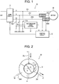
- FIG. 1 is an electric circuit diagram of a driving device D of a motor M in one embodiment (Embodiment 1) of the present invention
- FIG. 2 is a constitution diagram of the motor M
- FIG. 3 is a flow chart showing a control program of a control circuit C as control means constituting the driving device D.
- the driving device D of the present embodiment is constituted of: a main inverter circuit 1 (vector control inverter) including six switching elements connected to a direct-current power source DC as a battery of an automobile; the control circuit (control means) C which controls commutations of the switching elements of this main inverter circuit 1 to apply a pseudo three-phase alternating voltage to the motor M.
- a main inverter circuit 1 vehicle control inverter
- the control circuit (control means) C which controls commutations of the switching elements of this main inverter circuit 1 to apply a pseudo three-phase alternating voltage to the motor M.
- the motor M is a synchronous motor (FIG. 2) constituted of: a stator 3 around which three-phase coils 3U, 3V and 3W are wound by, for example, a concentrated widing; and an incorporated permanent magnet type rotor 4 which rotates in this stator 3.
- the three-phase coils 3U, 3V and 3W of U, V and W-phases of the stator 3 are connected to secondary lines 2U, 2V and 2W of phases of the main inverter circuit 1, respectively.
- the secondary lines 2V and 2W of the V and W-phases are provided with current sensors (current detecting means) 6V, 6W including current transformers for detecting currents which flow through the V and W-phases of the motor M, respectively, and outputs (detected current values) of the current sensors 6V, 6W are input into the control circuit C.
- the secondary lines 2U, 2V and 2W of the phases are connected to voltage detecting circuits (voltage detecting means) 7U, 7V and 7W including voltage divider resistances for detecting voltages induced in the lines, respectively.
- Terminal voltages (divided detected voltage values) of the voltage detecting circuits 7U, 7V and 7W are input into a rectangular wave control position detecting circuit (constituting the control means) 8.
- An output of this rectangular wave control position detecting circuit 8 is also input into the control circuit C.
- This rectangular wave control position detecting circuit 8 or the control circuit C is constituted of a general-purpose microcomputer. It is to be noted that in the present embodiment, the rectangular wave control position detecting circuit 8 is shown separately from the control circuit C, but needless to say, a function of the detecting circuit may impart to the control circuit C.
- the rectangular wave control position detecting circuit 8 is a circuit for detecting a magnetic pole position of the rotor 4 in a case where the motor M is rectangular wave control.
- the rectangular wave control is a so-called 120° energization system. Only two of the coils 3U, 3V and 3W of the phases of the stator 3 are energized, and any current is not passed through one remaining phase.
- FIG. 4 shows voltages of the phases of the motor M during the rectangular wave control.
- a current is passed from the U-phase to the V-phase (any current is not passed through the W-phase); in a mode II, the current is passed from the W-phase to the V-phase (any current is not passed through the U-phase); in a mode III, the current is passed from the W-phase to the U-phase (any current is not passed through the V-phase); in a mode IV, the current is passed from the V-phase to the U-phase (any current is not passed through the W-phase); in a mode V, the current is passed from the V-phase to the W-phase (any current is not passed through the U-phase); and in a mode VI, the current is passed from the U-phase to the W-phase (any current is not passed through the V-phase).
- an induced electromotive voltage appears (tilted line in FIG. 4).
- the induced electromotive voltages of the phases (through which any current is not passed) detected by the voltage detecting circuits 7U to 7W are input.
- a magnetic pole position estimating signal of the rotor 4 is obtained by a so-called analog filter system or a reference voltage comparison system without any sensor.
- this estimated magnetic pole position signal during the rectangular wave control is input into the control circuit C.
- the rectangular wave control is disadvantageous in voltage use ratio as compared with vector control. Moreover, since the control can be executed only every 60°, a control precision is lower than that of the vector control described later. There is also a disadvantage that a torque fluctuates more largely.
- the vector control is a so-called 180° energization system. Since a sine-wave voltage is applied to the three-phase coils 3U, 3V and 3W of the stator 3 to drive the motor. Therefore, there are more advantages in respect of the voltage use ratio and the torque fluctuation as compared with the rectangular wave control. However, since a current phase is controlled to be optimum with respect to a magnetic flux of a permanent magnet of the rotating rotor 4, fine information on the magnetic pole position is required.
- d-q axis (d-axis is a rotor magnetic flux axis, q-axis is an induced electromotive voltage axis) in which the magnetic pole position of the rotor 4 of the motor M is a rotary position (actual magnetic pole position) at a real angle ⁇ d
- dc-qc axis which an estimated angle ⁇ dc is obtained in the control circuit C.
- the main inverter circuit 1 are represented by a winding resistance r, a d-axis inductance Ld, a q-axis inductance Lq, a power generation constant kE, a d-axis current command Id*, a q-axis current command Iq*, a detected q-axis current value Iq, a speed command ⁇ 1* and the like together with the axial error ⁇ , the magnetic pole position of the rotor 4 is estimated.
- the control circuit C executes the sensor-less vector control of the motor M based on the magnetic pole position of the rotor 4 detected by such estimation.
- the control circuit C separates the current detected by the current sensors 6V, 6W and flowing from the secondary lines 2V, 2W to the motor M into a q-axis current component Iq and a d-axis current component Id, and independently controls the q-axis current command Iq* and the d-axis current command Id*.
- the control circuit determines magnitudes and phases of the voltage commands vd*, vq* so as to maximize the torque in a relation between a magnetic flux and a current phase, and a relation between the torque and an operation amount is set to be linear.
- control circuit C adjusts the phase of the current flowing through the motor M by use of a detected d-axis current value Id. Moreover, the circuit gives the voltage commands vd*, vq* to the main inverter circuit 1, and controls the switching elements to thereby drive the motor M at a revolution speed which satisfies the speed command.
- step S1 the control circuit C outputs the voltage command to the main inverter circuit 1, and subjects the coils 3U, 3V and 3W of the stator 3 of the motor M to the above-described rectangular wave control to generate a rotary magnetic field.
- the rotor 4 starts its rotation by this rotary magnetic field. Accordingly, the motor M starts.
- the control circuit C gives the voltage command to the main inverter circuit 1 during a constant V/F control described later to drive the motor M at a constant revolution speed.
- the control circuit C judges in step S2 whether or not the magnetic pole position estimating signal has been input from the rectangular wave control position detecting circuit 8.
- the rectangular wave control position detecting circuit 8 estimates the magnetic pole position of the rotor 4.
- the control circuit C advances to step S3 to fix the current phase to a predetermined value in synchronization of the estimated magnetic pole position, and raises the revolution speed of (accelerates) the motor M.
- the control circuit C judges in step S4 whether or not the revolution speed of the motor M has risen up to a predetermined shift revolution speed X Hz (in actual, 15 Hz to 30 Hz) sufficient for obtaining the induced electromotive voltage required for correctly estimating the magnetic pole position in executing the above-described sensor-less vector control.
- a predetermined shift revolution speed X Hz in actual, 15 Hz to 30 Hz
- the magnetic pole position input from the rectangular wave control position detecting circuit 8 just before in response to the magnetic pole position estimating signal of the rotor 4 is set as an initial value.
- the control circuit shifts to the vector control of the motor M by the above-described sensor-less vector control by use of the initial value of this magnetic pole position.
- the control circuit C estimates the magnetic pole position of the rotor 4 during the above vector control in step S5, and executes a vector control in step S6.
- the magnetic pole position just detected (estimated) during the rectangular wave control is used as the initial value of the rotor magnetic pole position during the sensor-less vector control, it is possible to minimize the axial error ⁇ between the actual rotor magnetic pole position and the estimated magnetic pole position during the shift to the sensor-less vector control. Step-out during the shift can be avoided to realize the stable driving control of the motor M from the starting till the sensor-less vector control.
- FIG. 5 the same characters as those of FIG. 1 denote the same or similar functions.
- the above-described voltage detecting circuits 7U to 7W are not necessary, and the rectangular wave control position detecting circuit 8 is not used either.
- a program of a control circuit C differs.
- step S10 of FIG. 6 the control circuit C subjects a motor M to vector control by a constant V/F control to generate a rotary magnetic field, thereby starting the motor.
- the control circuit C controls a speed command ⁇ 1 and a voltage command V1 beforehand at a constant ratio.
- the control circuit C gives, to a main inverter circuit 1, the speed command ⁇ 1 and the voltage command V1 obtained from a preset ratio, and drives the motor M. Since this system does not require magnetic pole position information of a rotor 4, a control system is remarkably simple, but there is a disadvantage that a transient vibration is generated in response to a rapid change of a load.
- the control circuit C accelerates a revolution speed of the motor M in step S11.
- the control circuit C estimates a magnetic pole position of the rotor 4 by a magnetic pole position estimating method during vector control.
- the control circuit C estimates the magnetic pole position, and continues to store the position during this constant V/F control.
- the control circuit C judges in step S13 whether or not the revolution speed of the motor M has risen up to a predetermined shift revolution speed X Hz.
- the shift revolution speed X Hz is reached, the previous magnetic pole position of the rotor 4 estimated during the constant V/F control is set as an initial value.
- the control circuit shifts to a vector control of the motor M by a sensor-less vector control using this initial value of the magnetic pole position.
- the control circuit C estimates the magnetic pole position of the rotor 4 during the vector control in step S14, and executes the vector control in step S15.
- the magnetic pole position just detected during the constant V/F control is used as the initial value of the rotor magnetic pole position during the sensor-less vector control, it is possible to minimize an axial error ⁇ between an actual rotor magnetic pole position and an estimated magnetic pole position in the same manner as in Embodiment 1. Also in this case, step-out during the shift can be avoided to realize the stable driving control of the motor M from the starting till the sensor-less vector control.
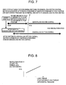
- a control circuit C when a control circuit C receives a speed command at a revolution speed lower than a shift revolution speed X Hz in a stopped state of a motor, the circuit once raises the speed up to the shift revolution speed X Hz, and shifts to a sensor-less vector control. Thereafter, the circuit lowers the speed down to a target revolution speed. This behavior is shown in FIG. 7.
- the control circuit C drives the motor M at the revolution speed lower than the shift revolution speed X Hz after starting the motor in this manner, the circuit once raises the speed up to the shift revolution speed X Hz, and shifts to the sensor-less vector control. Thereafter, the circuit lowers the revolution speed. In a case where this control is executed, even when it is necessary to operate the motor at the low revolution speed from the beginning of the starting, the sensor-less vector control can be executed without any trouble.
- a control circuit C changes a shift revolution speed X Hz in accordance with a load situation of a motor M.
- this load situation there are considered a load torque, a fluctuation of the load torque during one rotation, a pressure difference of a compressor and the like.
- the control circuit After accelerating the motor at a higher revolution speed, the control circuit shifts to a sensor-less vector control. Since step-out easily occurs with a worse load torque situation (larger load torque), it is possible to more securely avoid a danger of step-out during the shift by such a control.
Landscapes
- Engineering & Computer Science (AREA)
- Power Engineering (AREA)
- Control Of Motors That Do Not Use Commutators (AREA)
- Control Of Ac Motors In General (AREA)
Applications Claiming Priority (1)
| Application Number | Priority Date | Filing Date | Title |
|---|---|---|---|
| JP2005271765A JP4566100B2 (ja) | 2005-09-20 | 2005-09-20 | 電動機の駆動装置 |
Publications (1)
| Publication Number | Publication Date |
|---|---|
| EP1764904A2 true EP1764904A2 (de) | 2007-03-21 |
Family
ID=37603320
Family Applications (1)
| Application Number | Title | Priority Date | Filing Date |
|---|---|---|---|
| EP06019484A Withdrawn EP1764904A2 (de) | 2005-09-20 | 2006-09-18 | Antriebsvorrichtung für einen Motor |
Country Status (3)
| Country | Link |
|---|---|
| US (1) | US7375482B2 (de) |
| EP (1) | EP1764904A2 (de) |
| JP (1) | JP4566100B2 (de) |
Cited By (5)
| Publication number | Priority date | Publication date | Assignee | Title |
|---|---|---|---|---|
| EP2065172A1 (de) * | 2008-07-24 | 2009-06-03 | Siemens Aktiengesellschaft | Spindelpresse und Verfahren zu deren Betrieb |
| JP2015220944A (ja) * | 2014-05-21 | 2015-12-07 | 富士電機株式会社 | 同期電動機のセンサレス駆動装置 |
| CN106817061A (zh) * | 2015-11-27 | 2017-06-09 | 沈阳高精数控智能技术股份有限公司 | 一种检测转子初始位置的方法 |
| EP2377237A4 (de) * | 2008-12-17 | 2017-10-25 | LG Electronics Inc. | Vorrichtung und verfahren für das starten eines sensorlosen bldc-motors |
| US20220329180A1 (en) * | 2019-04-25 | 2022-10-13 | Black & Decker Inc. | Low-speed sensorless brushless motor control in a power tool |
Families Citing this family (6)
| Publication number | Priority date | Publication date | Assignee | Title |
|---|---|---|---|---|
| CN102171923B (zh) * | 2008-08-28 | 2014-03-12 | Thk株式会社 | 线性同步电机控制装置 |
| KR101490185B1 (ko) * | 2008-12-17 | 2015-02-11 | 엘지전자 주식회사 | 센서리스 bldc 모터의 기동 장치 및 방법 |
| KR101514663B1 (ko) * | 2008-12-17 | 2015-05-04 | 엘지전자 주식회사 | 센서리스 bldc 모터의 기동 장치 및 방법 |
| IT1394426B1 (it) * | 2009-06-05 | 2012-06-15 | Reel S R L Unipersonale | Metodo di controllo di un motore |
| JP2013106478A (ja) * | 2011-11-15 | 2013-05-30 | Sanki Eng Co Ltd | コンベヤ駆動装置 |
| JP6274069B2 (ja) * | 2014-10-17 | 2018-02-07 | 株式会社デンソー | モータ制御装置 |
Family Cites Families (12)
| Publication number | Priority date | Publication date | Assignee | Title |
|---|---|---|---|---|
| US4641066A (en) * | 1984-10-04 | 1987-02-03 | Nippondenso Co., Ltd. | Control apparatus for brushless motor |
| JPH07118944B2 (ja) * | 1986-03-17 | 1995-12-18 | 株式会社日立製作所 | ブラシレス直流モ−タ |
| AU633738B2 (en) * | 1990-06-20 | 1993-02-04 | Matsushita Electric Industrial Co., Ltd. | Brushless DC motor |
| US5254914A (en) * | 1990-06-29 | 1993-10-19 | Seagate Technology, Inc. | Position detection for a brushless DC motor without Hall effect devices using a mutual inductance detection method |
| US5223772A (en) * | 1992-02-28 | 1993-06-29 | Sgs-Thomson Microelectronics, Inc. | Method and apparatus for providing the lock of a phase-locked loop system from frequency sweep |
| JP3283377B2 (ja) * | 1994-05-10 | 2002-05-20 | 株式会社日立製作所 | 直流電動機の同期起動装置 |
| JP3333793B2 (ja) * | 1994-09-22 | 2002-10-15 | サンデン株式会社 | ブラシレスモータ装置 |
| JP3612636B2 (ja) | 1996-09-18 | 2005-01-19 | 有限会社シー・アンド・エス国際研究所 | 同期電動機のベクトル制御方法 |
| JP3833918B2 (ja) * | 2001-09-28 | 2006-10-18 | シャープ株式会社 | モータ制御装置 |
| JP3783159B2 (ja) * | 2002-07-10 | 2006-06-07 | 株式会社日立製作所 | 同期電動機の駆動制御装置 |
| JP3993502B2 (ja) * | 2002-10-21 | 2007-10-17 | 株式会社ルネサステクノロジ | 多相直流モータの回転駆動制御装置および起動方法 |
| JP2005210813A (ja) * | 2004-01-21 | 2005-08-04 | Mitsubishi Heavy Ind Ltd | ブラシレスdcモータシステム,及びブラシレスdcモータ駆動方法 |
-
2005
- 2005-09-20 JP JP2005271765A patent/JP4566100B2/ja not_active Expired - Fee Related
-
2006
- 2006-09-18 EP EP06019484A patent/EP1764904A2/de not_active Withdrawn
- 2006-09-19 US US11/523,002 patent/US7375482B2/en not_active Expired - Fee Related
Cited By (7)
| Publication number | Priority date | Publication date | Assignee | Title |
|---|---|---|---|---|
| EP2065172A1 (de) * | 2008-07-24 | 2009-06-03 | Siemens Aktiengesellschaft | Spindelpresse und Verfahren zu deren Betrieb |
| EP2377237A4 (de) * | 2008-12-17 | 2017-10-25 | LG Electronics Inc. | Vorrichtung und verfahren für das starten eines sensorlosen bldc-motors |
| JP2015220944A (ja) * | 2014-05-21 | 2015-12-07 | 富士電機株式会社 | 同期電動機のセンサレス駆動装置 |
| CN106817061A (zh) * | 2015-11-27 | 2017-06-09 | 沈阳高精数控智能技术股份有限公司 | 一种检测转子初始位置的方法 |
| CN106817061B (zh) * | 2015-11-27 | 2019-05-14 | 沈阳高精数控智能技术股份有限公司 | 一种检测转子初始位置的方法 |
| US20220329180A1 (en) * | 2019-04-25 | 2022-10-13 | Black & Decker Inc. | Low-speed sensorless brushless motor control in a power tool |
| US11750124B2 (en) * | 2019-04-25 | 2023-09-05 | Black & Decker Inc. | Low-speed sensorless brushless motor control in a power tool |
Also Published As
| Publication number | Publication date |
|---|---|
| US7375482B2 (en) | 2008-05-20 |
| JP2007089247A (ja) | 2007-04-05 |
| US20070063666A1 (en) | 2007-03-22 |
| JP4566100B2 (ja) | 2010-10-20 |
Similar Documents
| Publication | Publication Date | Title |
|---|---|---|
| US9263979B2 (en) | Method for smooth motor startup | |
| US7375485B2 (en) | Control systems and methods for starting permanent magnet rotating machines | |
| EP2696496B1 (de) | Motorsteuerungsvorrichtung | |
| EP1906116A2 (de) | Steuerungsvorrichtung für einen Motor eines Kühlkompressors | |
| KR20170113140A (ko) | 인버터 제어 장치 및 차재 유체 기계 | |
| CN107980203B (zh) | 电动机的控制装置 | |
| JP2009268304A (ja) | インバータ装置 | |
| JP6908888B2 (ja) | 同期電動機の制御装置 | |
| KR102260154B1 (ko) | 차량 탑재 유체 기계 및 제어 방법 그리고 기록 매체 | |
| US7375482B2 (en) | Driving device of motor | |
| JP6463966B2 (ja) | モータ駆動装置およびモータ駆動用モジュール並びに冷凍機器 | |
| US7388340B2 (en) | Driving device of motor | |
| US12255558B2 (en) | Motor controller, motor system and method for controlling motor | |
| JP6806272B1 (ja) | モータの減磁診断装置およびモータ制御装置の減磁診断方法 | |
| JP5908205B2 (ja) | 回転センサレス制御装置 | |
| Suzuki et al. | Minimum current start-up method by combined use of two position-sensorless controls | |
| JP7024289B2 (ja) | モータ制御装置 | |
| JP5157622B2 (ja) | インバータ装置 | |
| JP4791319B2 (ja) | インバータ装置、圧縮機駆動装置および冷凍・空調装置 | |
| JP2009254191A (ja) | モータ制御装置、圧縮装置、冷凍装置および空調装置 | |
| JP2014064441A (ja) | モータ制御装置 | |
| JP2013121280A (ja) | モータ制御装置 | |
| CN220605792U (zh) | 启动控制装置及压缩机 | |
| Bahrami-Fard et al. | A novel If startup strategy with smooth transition to sensorless control for CSI-fed PMSM drives used in submersible pumps | |
| Bahrami-Fard et al. | Sensorless Field Oriented Control of CSI-Fed PMSM Drives Used in Submersible Pumps |
Legal Events
| Date | Code | Title | Description |
|---|---|---|---|
| PUAI | Public reference made under article 153(3) epc to a published international application that has entered the european phase |
Free format text: ORIGINAL CODE: 0009012 |
|
| AK | Designated contracting states |
Kind code of ref document: A2 Designated state(s): AT BE BG CH CY CZ DE DK EE ES FI FR GB GR HU IE IS IT LI LT LU LV MC NL PL PT RO SE SI SK TR |
|
| AX | Request for extension of the european patent |
Extension state: AL BA HR MK YU |
|
| STAA | Information on the status of an ep patent application or granted ep patent |
Free format text: STATUS: THE APPLICATION HAS BEEN WITHDRAWN |
|
| 18W | Application withdrawn |
Effective date: 20140224 |