EP1764909A2 - Dispositif de commande d'un moteur - Google Patents
Dispositif de commande d'un moteur Download PDFInfo
- Publication number
- EP1764909A2 EP1764909A2 EP06019485A EP06019485A EP1764909A2 EP 1764909 A2 EP1764909 A2 EP 1764909A2 EP 06019485 A EP06019485 A EP 06019485A EP 06019485 A EP06019485 A EP 06019485A EP 1764909 A2 EP1764909 A2 EP 1764909A2
- Authority
- EP
- European Patent Office
- Prior art keywords
- motor
- current
- control
- sensor
- permanent magnet
- Prior art date
- Legal status (The legal status is an assumption and is not a legal conclusion. Google has not performed a legal analysis and makes no representation as to the accuracy of the status listed.)
- Withdrawn
Links
- 230000004907 flux Effects 0.000 claims abstract description 12
- 238000010586 diagram Methods 0.000 description 6
- 238000001514 detection method Methods 0.000 description 4
- 238000000034 method Methods 0.000 description 3
- 230000001360 synchronised effect Effects 0.000 description 3
- CURLTUGMZLYLDI-UHFFFAOYSA-N Carbon dioxide Chemical compound O=C=O CURLTUGMZLYLDI-UHFFFAOYSA-N 0.000 description 2
- 230000006835 compression Effects 0.000 description 2
- 238000007906 compression Methods 0.000 description 2
- 229910002092 carbon dioxide Inorganic materials 0.000 description 1
- 239000001569 carbon dioxide Substances 0.000 description 1
- 238000010248 power generation Methods 0.000 description 1
- 230000005855 radiation Effects 0.000 description 1
- 239000003507 refrigerant Substances 0.000 description 1
- 238000004804 winding Methods 0.000 description 1
Images
Classifications
-
- H—ELECTRICITY
- H02—GENERATION; CONVERSION OR DISTRIBUTION OF ELECTRIC POWER
- H02P—CONTROL OR REGULATION OF ELECTRIC MOTORS, ELECTRIC GENERATORS OR DYNAMO-ELECTRIC CONVERTERS; CONTROLLING TRANSFORMERS, REACTORS OR CHOKE COILS
- H02P21/00—Arrangements or methods for the control of electric machines by vector control, e.g. by control of field orientation
- H02P21/04—Arrangements or methods for the control of electric machines by vector control, e.g. by control of field orientation specially adapted for very low speeds
-
- H—ELECTRICITY
- H02—GENERATION; CONVERSION OR DISTRIBUTION OF ELECTRIC POWER
- H02P—CONTROL OR REGULATION OF ELECTRIC MOTORS, ELECTRIC GENERATORS OR DYNAMO-ELECTRIC CONVERTERS; CONTROLLING TRANSFORMERS, REACTORS OR CHOKE COILS
- H02P21/00—Arrangements or methods for the control of electric machines by vector control, e.g. by control of field orientation
- H02P21/02—Arrangements or methods for the control of electric machines by vector control, e.g. by control of field orientation specially adapted for optimising the efficiency at low load
-
- H—ELECTRICITY
- H02—GENERATION; CONVERSION OR DISTRIBUTION OF ELECTRIC POWER
- H02P—CONTROL OR REGULATION OF ELECTRIC MOTORS, ELECTRIC GENERATORS OR DYNAMO-ELECTRIC CONVERTERS; CONTROLLING TRANSFORMERS, REACTORS OR CHOKE COILS
- H02P21/00—Arrangements or methods for the control of electric machines by vector control, e.g. by control of field orientation
- H02P21/24—Vector control not involving the use of rotor position or rotor speed sensors
Definitions
- the present invention relates to a driving device which controls a permanent magnet type motor by a sensor-less vector system without using any magnetic pole position sensor.
- a vector control is usually used.
- This vector control is a technique in which a current flowing through the motor is separated into a torque current component and a field current component, and an optimum current value is calculated in accordance with a position of a rotor, so that an efficient control having little torque fluctuation is possible as compared with a rectangular-wave inverter.
- a magnetic pole position of the rotor needs to be grasped, but in a sensor-less vector control for a high speed in which any magnetic pole position sensor is not used, instead of the magnetic pole position sensor, a value of the current flowing through the motor is utilized to estimate the magnetic pole position.
- the current flowing through the motor is detected using a current detector such as a current transformer or a resistance, and the detected current is separated into a field current component Id and a torque current component Iq to estimate the magnetic pole position.
- a dc-qc rotation coordinate system In an actual vector control, with respect to a d-q rotation coordinate system in which the magnetic pole position of the rotor of the motor is a rotary position at a real angle ⁇ d, a dc-qc rotation coordinate system is supposed in which an estimated angle ⁇ dc is obtained in the control system. An axial error ⁇ between the coordinate systems is estimated and calculated. So as to set this axial error ⁇ to zero, a voltage command value of the inverter is fed back and corrected, and this allows an actual magnetic pole position to meet a controlled magnetic pole position.
- the resolution (current detecting level) of the current detector is raised, but a problem occurs in the detection of the current at the high speed and with the high load. It has been difficult to use the single detector from the operation at the low rotation speed and with the low load till the operation at the high rotation speed and with the high load.
- the present invention has been developed in order to solve such a conventional technical problem, and an object thereof is to provide a driving device which is capable of detecting a current of a motor without any trouble even in a low rotation speed/low load state to continue a sensor-less vector control, in a case where the motor is driven by the sensor-less vector control.
- a first aspect of the present invention is directed to a driving device of a motor comprising: a main inverter circuit which applies a pseudo alternating voltage to a permanent magnet type motor to drive the motor; current detecting means for detecting a current which flows through the motor; and control means for controlling the main inverter circuit, wherein the control means separates the current flowing through the motor into a torque current component and a field current component based on an output of the current detecting means to control commutation of the main inverter circuit by a sensor-less vector control, and in a case where the motor is operated in a predetermined low rotation speed region and/or the motor is brought into a predetermined low load state, the control means permits the flow of the field current component in a direction to weaken a magnetic flux of a permanent magnet.
- a second aspect of the present invention is directed to the above driving device of the motor, wherein the control means changes a value of the field current component in the direction to weaken the magnetic flux of the permanent magnet in accordance with a rotation speed and/or a load state of the motor.
- the control means permits the flow of the field current component in the direction to weaken the magnetic flux of the permanent magnet, when the motor is operated in the predetermined low rotation speed region and/or the motor is brought into the predetermined low load state. Therefore, the whole current flowing through the motor increases even with the identical torque.
- the current detecting means can detect the current flowing through the motor without any trouble, and it is possible to avoid step-out due to failure in detection of a magnetic pole position in advance.
- the value of the field current component in the direction to weaken the magnetic flux of the permanent magnet is changed in accordance with the rotation speed and/or the load state of the motor as in the second aspect of the present invention, it is possible to prevent a useless current increase while securing the current value necessary and sufficient for detecting the magnetic pole position.
- a motor M is an incorporated permanent magnet type synchronous motor to drive a motor compressor (not shown) which is to be mounted on, for example, a car air conditioner and in which carbon dioxide is used as a refrigerant.
- the motor M is stored together with, for example, a rotary compression element in a shell of such a compressor, and is used to rotate and drive the compression element.
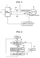
- FIG. 1 is an electric circuit diagram of a driving device D of the motor M in one embodiment to which the present invention has been applied
- FIG. 2 is a flow chart showing a control program of a control circuit C as control means constituting the driving device D.
- the driving device D of the present embodiment is constituted of: a main inverter circuit 1 (three-phase inverter) including six switching devices connected to a direct-current power source DC as a battery of an automobile; the control circuit (control means) C which controls commutations of the switching devices of this main inverter circuit 1 to apply a pseudo three-phase alternating voltage to the motor M and the like.
- the motor M is a synchronous motor constituted of: a stator around which three-phase coils are wound by, for example, a series system; and an incorporated permanent magnet (IPM) type rotor which rotates in this stator.
- the three-phase coils of U, V and W-phases of the stator are connected to secondary lines 2U, 2V and 2W of phases of the main inverter circuit 1, respectively.
- the secondary lines 2V and 2W of the V and W-phases are provided with current sensors (current detecting means) 6V, 6W including current transformers for detecting currents which flow through the V and W-phases of the motor M, respectively, and outputs (detected current values) of the current sensors 6V, 6W are input into the control circuit C.
- current sensors current detecting means
- 6V, 6W including current transformers for detecting currents which flow through the V and W-phases of the motor M, respectively, and outputs (detected current values) of the current sensors 6V, 6W are input into the control circuit C.
- This control circuit C outputs a voltage command to the main inverter circuit 1, and controls the commutations of the switching devices to thereby drive the motor M by three-phase conducting under a sensor-less vector control.
- This three-phase conducting is a so-called 180° conducting system. Since a sine-wave voltage is applied to the three-phase coils of the stator to drive the motor, a voltage use ratio is satisfactory, and torque fluctuations are reduced. However, since a current phase is controlled to be optimum with respect to a magnetic flux of a permanent magnet of the rotating rotor, fine information on a magnetic pole position is required.
- d-axis is a direction of an N-pole of the permanent magnet
- q-axis is a direction (electric angle) advanced by ⁇ /2 from the d-axis) in which the magnetic pole position of the rotor of the motor M is a rotary position (actual magnetic pole position) at a real angle ⁇ d
- dc-qc rotation coordinate system in which an estimated angle ⁇ dc is obtained in the control circuit C.
- the current flowing from the secondary lines 2V, 2W to the motor M and detected by the current sensors 6V, 6W is separated into a torque current component (detected torque current value Iq) and a field current component (detected field current value Id).
- the control circuit C executes the sensor-less vector control of the motor M based on the magnetic pole position of the rotor detected by such estimation.
- the control circuit C separates the whole current flowing through the motor M into the torque current component (detected torque current value Iq) and a field current component (detected field current value Id), and independently controls the torque current command Iq* and the field current command Id*. Accordingly, to validate the input speed command ⁇ 1*, the control circuit determines magnitudes and phases of the voltage commands vd*, vq* so as to establish an optimum relation between the magnetic flux and the current phase, and a relation between the torque and an operation amount is set to be linear.
- control circuit C adjusts the phase of the current flowing through the motor M by use of the detected d-axis field current value Id. Moreover, the circuit gives the voltage commands vd*, vq* to the main inverter circuit 1, and controls the commutations of the switching devices to thereby drive the motor M at such a rotation speed as to satisfy the speed command.
- step S1 the control circuit C judges whether or not the present speed command indicates a predetermined low rotation speed (set frequency of, e.g., 30 Hz or the like) or less and/or whether or not the load of the motor M indicates a predetermined low load state (set load) or less.
- the operation advances to step S2 to set, to zero, the field current command Id* to be passed along the d-axis, and advances to step S4.
- control circuit C executes the three-phase conducting of the motor M by the above-described sensor-less vector control using the magnetic pole position estimated as described above.
- step S3 calculates a value of the current to be passed along the d-axis in a direction to weaken the magnetic flux of the permanent magnet of the rotor.
- the rotation speed is not very low and the load is not very light (the predetermined low rotation speed or less, and the low load or less are indicated in either case)
- the negative value of the current to be passed along the d-axis is reduced.
- the negative value of the current to be passed along the d-axis is calculated in this manner to generate the field current command Id*, and the operation shifts to the step S4.
- a negative d-axis current field current component -Id
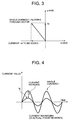
- the whole current I flowing through the motor M is larger than the torque current component Iq.
- FIG. 3 when the field current component -Id is not passed, the current flowing through the motor M indicates a magnitude of Iq.
- the component -Id When the component -Id is passed, however, the whole synthesized current indicates I, and becomes larger than Iq.
- FIG. 4 A difference between the currents is shown as a current increase. It is to be noted that the phases of the currents actually deviate. However, for ease of seeing, FIG. 4 shows that the phases are matched.
- the control circuit C permits the flow of the field current component (-Id) in the direction to weaken the magnetic flux of the permanent magnet. Therefore, even with the identical torque, the whole current I flowing through the motor M increases.
- the current sensors can detect the current I flowing through the motor M without any trouble, and it is possible to avoid, in advance, step-out due to failure in detection of the magnetic pole position of the rotor.
- the value of the field current component (-Id) in the direction to weaken the magnetic flux of the permanent magnet is changed in accordance with the rotation speed and/or the load state of the motor M. Therefore, while securing the current I necessary and sufficient for the detection of the magnetic pole position, a useless current increase can be prevented.
Landscapes
- Engineering & Computer Science (AREA)
- Power Engineering (AREA)
- Control Of Ac Motors In General (AREA)
- Control Of Motors That Do Not Use Commutators (AREA)
Applications Claiming Priority (1)
| Application Number | Priority Date | Filing Date | Title |
|---|---|---|---|
| JP2005271770A JP2007089248A (ja) | 2005-09-20 | 2005-09-20 | 電動機の駆動装置 |
Publications (1)
| Publication Number | Publication Date |
|---|---|
| EP1764909A2 true EP1764909A2 (fr) | 2007-03-21 |
Family
ID=37561187
Family Applications (1)
| Application Number | Title | Priority Date | Filing Date |
|---|---|---|---|
| EP06019485A Withdrawn EP1764909A2 (fr) | 2005-09-20 | 2006-09-18 | Dispositif de commande d'un moteur |
Country Status (3)
| Country | Link |
|---|---|
| US (1) | US7388340B2 (fr) |
| EP (1) | EP1764909A2 (fr) |
| JP (1) | JP2007089248A (fr) |
Cited By (1)
| Publication number | Priority date | Publication date | Assignee | Title |
|---|---|---|---|---|
| CN102104360A (zh) * | 2009-12-18 | 2011-06-22 | Abb公司 | 用于控制永磁同步电机的方法和设备 |
Families Citing this family (13)
| Publication number | Priority date | Publication date | Assignee | Title |
|---|---|---|---|---|
| US7622877B2 (en) * | 2007-03-13 | 2009-11-24 | Gm Global Technology Operations, Inc. | Method and system for controlling permanent magnet AC machines |
| KR101468736B1 (ko) * | 2007-11-22 | 2014-12-03 | 엘지전자 주식회사 | 모터, 세탁기 모터의 제어장치 및 세탁기 모터의 제어방법 |
| KR101470628B1 (ko) * | 2008-02-13 | 2014-12-08 | 엘지전자 주식회사 | 모터, 이를 포함하는 세탁기 및 그 제어방법 |
| KR101451429B1 (ko) * | 2008-02-13 | 2014-10-15 | 엘지전자 주식회사 | 모터, 이를 포함하는 세탁기 및 그 제어방법 |
| CN102171923B (zh) * | 2008-08-28 | 2014-03-12 | Thk株式会社 | 线性同步电机控制装置 |
| US8264192B2 (en) | 2009-08-10 | 2012-09-11 | Emerson Climate Technologies, Inc. | Controller and method for transitioning between control angles |
| US8698433B2 (en) | 2009-08-10 | 2014-04-15 | Emerson Climate Technologies, Inc. | Controller and method for minimizing phase advance current |
| US8508166B2 (en) | 2009-08-10 | 2013-08-13 | Emerson Climate Technologies, Inc. | Power factor correction with variable bus voltage |
| US9634593B2 (en) | 2012-04-26 | 2017-04-25 | Emerson Climate Technologies, Inc. | System and method for permanent magnet motor control |
| WO2014026124A1 (fr) | 2012-08-10 | 2014-02-13 | Emerson Climate Technologies, Inc. | Commande d'entraînement de moteur utilisant une suppression d'impulsion de modulation d'impulsions en largeur |
| JP5812021B2 (ja) | 2013-02-08 | 2015-11-11 | 株式会社デンソー | 交流電動機の制御装置 |
| CN106712632B (zh) * | 2017-03-28 | 2024-01-02 | 核工业理化工程研究院 | 交流永磁同步电机无位置传感器的控制装置及其启动方法 |
| CN113785485B (zh) * | 2019-04-15 | 2025-10-10 | 米沃奇电动工具公司 | 电动工具的无传感器电机控制 |
Family Cites Families (8)
| Publication number | Priority date | Publication date | Assignee | Title |
|---|---|---|---|---|
| US6008614A (en) * | 1991-03-08 | 1999-12-28 | Honda Giken Kogyo Kabushiki Kaisha | Synchronous motor with permanent magnets and motor system |
| JPH08182398A (ja) * | 1994-12-27 | 1996-07-12 | Fuji Electric Co Ltd | 永久磁石形同期電動機の駆動装置 |
| EP1378990B1 (fr) * | 2001-03-02 | 2007-12-12 | Matsushita Electric Industrial Co., Ltd. | Contrôleur pour un moteur électrique |
| JP3783159B2 (ja) | 2002-07-10 | 2006-06-07 | 株式会社日立製作所 | 同期電動機の駆動制御装置 |
| US6864662B2 (en) * | 2003-04-30 | 2005-03-08 | Visteon Global Technologies, Inc. | Electric power assist steering system and method of operation |
| CN100448158C (zh) * | 2003-04-30 | 2008-12-31 | 松下电器产业株式会社 | 电动机驱动装置 |
| JP4539065B2 (ja) * | 2003-09-29 | 2010-09-08 | ダイキン工業株式会社 | モータの制御方法及びモータの制御装置 |
| US7495404B2 (en) * | 2005-08-17 | 2009-02-24 | Honeywell International Inc. | Power factor control for floating frame controller for sensorless control of synchronous machines |
-
2005
- 2005-09-20 JP JP2005271770A patent/JP2007089248A/ja active Pending
-
2006
- 2006-09-18 EP EP06019485A patent/EP1764909A2/fr not_active Withdrawn
- 2006-09-20 US US11/523,562 patent/US7388340B2/en not_active Expired - Fee Related
Cited By (4)
| Publication number | Priority date | Publication date | Assignee | Title |
|---|---|---|---|---|
| CN102104360A (zh) * | 2009-12-18 | 2011-06-22 | Abb公司 | 用于控制永磁同步电机的方法和设备 |
| EP2337211A1 (fr) * | 2009-12-18 | 2011-06-22 | ABB Oy | Procédé et agencement pour la commande de machines synchrones à aimant permanent |
| CN102104360B (zh) * | 2009-12-18 | 2013-09-25 | Abb公司 | 用于控制永磁同步电机的方法和设备 |
| US8723459B2 (en) | 2009-12-18 | 2014-05-13 | Abb Oy | Method and arrangement for controlling permanent magnet synchronous machines |
Also Published As
| Publication number | Publication date |
|---|---|
| JP2007089248A (ja) | 2007-04-05 |
| US7388340B2 (en) | 2008-06-17 |
| US20070063667A1 (en) | 2007-03-22 |
Similar Documents
| Publication | Publication Date | Title |
|---|---|---|
| JP4022630B2 (ja) | 電力変換制御装置、電力変換制御方法、および電力変換制御用プログラム | |
| US9577560B2 (en) | Synchronous machine control device | |
| CN102487264B (zh) | 用于感应电动机的磁通控制器 | |
| EP1730836B1 (fr) | Unite de commande de puissance instantanee a cadre flottant | |
| US7388340B2 (en) | Driving device of motor | |
| US7538510B2 (en) | Controller for motor | |
| KR20090084044A (ko) | 모터의 기동방법 | |
| US11396092B2 (en) | Electric power tool provided with motor controller controlling motor including limiter for limitting current contributing to torque generation | |
| JP3661864B2 (ja) | ステッピングモータの駆動装置 | |
| WO2012029715A1 (fr) | Dispositif d'entraînement de moteur électrique | |
| WO2015056541A1 (fr) | Dispositif d'entraînement pour un moteur électrique | |
| US11482959B2 (en) | Motor driving method and motor driving system | |
| US7375482B2 (en) | Driving device of motor | |
| JP5305933B2 (ja) | モータドライブシステム | |
| JP4053511B2 (ja) | 巻線界磁式同期機のベクトル制御装置 | |
| JP5363129B2 (ja) | インバータ制御装置 | |
| JP5034888B2 (ja) | 同期電動機のV/f制御装置 | |
| JP2019068515A (ja) | モータ制御装置 | |
| JP6307223B2 (ja) | 三相同期電動機の制御装置及びそれを用いた三相同期電機駆動システム、一体型電動機システム、ポンプシステム、及び圧縮機システム、並びに三相同期電動機の制御方法 | |
| JP5479094B2 (ja) | 同期モータの制御方法及び制御装置 | |
| JP2009254191A (ja) | モータ制御装置、圧縮装置、冷凍装置および空調装置 | |
| CN220605792U (zh) | 启动控制装置及压缩机 | |
| TWI756975B (zh) | 馬達驅動方法 | |
| JP7567532B2 (ja) | 永久磁石同期電動機の高効率運転制御装置および高効率運転制御方法 | |
| JP2023080554A (ja) | モータ制御装置 |
Legal Events
| Date | Code | Title | Description |
|---|---|---|---|
| PUAI | Public reference made under article 153(3) epc to a published international application that has entered the european phase |
Free format text: ORIGINAL CODE: 0009012 |
|
| AK | Designated contracting states |
Kind code of ref document: A2 Designated state(s): AT BE BG CH CY CZ DE DK EE ES FI FR GB GR HU IE IS IT LI LT LU LV MC NL PL PT RO SE SI SK TR |
|
| AX | Request for extension of the european patent |
Extension state: AL BA HR MK YU |
|
| STAA | Information on the status of an ep patent application or granted ep patent |
Free format text: STATUS: THE APPLICATION HAS BEEN WITHDRAWN |
|
| 18W | Application withdrawn |
Effective date: 20140224 |